
GAS COOKTOPS
INSTALLATION INSTRUCTIONS
INSTRUCCIONES DE INSTALACIÓN
INSTRUCTIONS D’INSTALLATION
ISTRUZIONI PER L’INSTALLAZIONE
INSTALLATIONSANWEISUNGEN
Page is loading ...
Page is loading ...

As you follow these instruc tions, you will
notice WARNING and CAUTION symbols. This
blocked information is impor tant for the safe
and efficient installation of Wolf equipment.
There are two types of potential hazards that
may occur during installation.
Another footnote we would like to identify is
IMPORTANT NOTE: This highlights informa-
tion that is especially relevant to a problem-
free installation.
signals a situation where minor injury or
product damage may occur if you do not
follow instructions.
states a hazard that may cause serious
injury or death if precautions are not
followed.
WOLF
®
is a registered trademark of Wolf Appliance, Inc.
C O N TA C T
I N F O R M AT I O N
Website:
wolfappliance.com

5
IN STA LL AT ION R E Q U I R E M E N T S
WHAT TO DO IF YOU SMELL GAS:
Do not try to light any appliance.
Do not touch any electrical switch.
Do not use any phone in your
building.
Immediately call your gas supplier
from a neighbor’s phone. Follow
the gas supplier’s instructions.
If you cannot reach your gas
supplier, call the fire department.
W O L F GA S C OO KTO PS
IMPORTANT NOTE:
Installation and service must be
performed by a qualified installer,
service agency or the gas supplier.
Do not store or use gasoline or
other flammable vapors and liquids
in the vicinity of this or any other
appliance.
The use of a gas cooking appliance
results in the production of heat and
moisture in the room in which it is
installed. Ensure that the kitchen is
well ventilated; keep natural ventila-
tion holes open or install a mechani-
cal ventilation device (mechanical
extractor hood)
Prolonged intensive use of the appli-
ance may for additional ventilation,
for example opening of a window, or
more effective ventilation, for
example increasing the level of
mechanical ventilation where
present.
This appliance shall be installed
in accordance with the regula-
tions in force and only used in a
well ventilated space. Read the
instructions before installing or
using this appliance.

6
IN STA LL AT ION R E Q U I R E M E N T S
IMPORTANT NOTE: This installation must
be completed by a qualified installer,
service agency or gas supplier.
IMPORTANT NOTE:
Save these Installation
Instructions for the local inspector’s use.
Please read the entire Installation Instruc-
tions prior to installation.
Installer:
please retain these instructions
for local inspector’s reference, then leave
them with the homeowner.
Homeowner:
please read and keep these
instructions for future reference and be sure
to read the entire Use & Care Information
prior to use.
IMPORTANT NOTE:
This appliance must be
installed in accordance with local codes. The
correct voltage, frequency and amperage must
be supplied to the appliance from a dedicated,
grounded circuit which is protected by a
properly sized circuit breaker or time delay
fuse. The proper voltage, frequency, and
amperage ratings are listed on the product
rating plate.
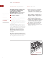
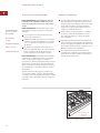
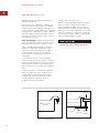
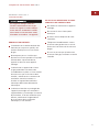
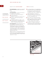
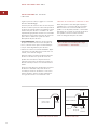
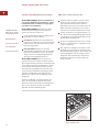
Record the model and serial numbers before
installing the cooktop. Both numbers are listed
on the rating plate, located on the underside of
the cooktop. Refer to the illustration below.
BE FOR E YO U S TA RT
Proper installation is your responsibility.
Have a qualified technician install this
cooktop. You must also assure that electri-
cal installation is adequate and in compli-
ance with all local codes and ordinances.
Prior to installation, ensure that the local
distribution conditions (nature of the gas
and gas pressure) and the adjustment of
the appliance are compatible.
Proper gas supply connection must be
available; refer to Gas Supply Requirements
on page 12. Electrical ground is required;
see Electrical Requirements on page 13.
The adjustment conditions for this appli-
ance are stated on the label (or rating
plate). The data plate can be found on the
underside of the cooktop.
W O L F GA S C OOK TOP S
Rating plate location
Location of rating
plate under cooktop
R
AT I N G P L AT E
I N F O R M AT I O N
Model Number
Serial Number

7
IN STA LL AT ION I N S T R U C T I O N S
L O C AT I O N R E Q U I R E M E N T S
Illustrations on the following pages provide the
overall dimensions, countertop cut-out and
installation specifications for Wolf gas
cooktops. Maintain the following minimum
installation dimensions:
Minimum horizontal clearance from the
sides and back of the cooktop cut-out to
adjacent vertical combustible construction,
extending a minimum of 457 mm above the
countertop, is as follows: 178 mm from side
edges of cut-out for the 381 mm cooktop;
229 mm from side edges of cut-out for the
762 mm and 914 mm cooktops; 64 mm
from rear edge of cut-out.
Minimum vertical distance between the
countertop and combustible materials
above the cooktop must be 762 mm.
Maximum 330 mm depth of overhead side
cabinets directly above and within side
clearance.
IMPORTANT NOTE:
When installing a ventila-
tion hood, refer to the specific requirements
of the hood for the minimum dimension to
countertop.
BE FOR E YO U S TA RT
Check the location where the cooktop will
be installed. The location should be away
from strong draft areas, such as windows,
doors and strong heating vents or fans. Do
not obstruct flow of combustion and
ventilation air.
This appliance is not connected to a
combustion products evacuation device. It
shall be installed and connected in accor-
dance with current installation regulations.
Particular attention shall be given to the
relevant requirements regarding ventilation.
SI TE P R E PA R AT I O N
C O U N T E RT O P C U T- O U T D I M E N S I O N S
IMPORTANT NOTE:
Countertop opening
dimensions shown on the following pages
must be used. The dimensions shown provide
for required clearances.
These cooktops are designed to fit a standard
610 mm deep base cabinet with a 635 mm
deep countertop. Before making the counter-
top cut-out, verify that the cooktop will clear
the side walls of the base cabinet below. There
should be at least 140 mm clearance between
the countertop and any combustible surface
directly below the unit.
IMPORTANT NOTE:
Do not seal the cooktop
to the countertop. It must be removed if
service is necessary.
Failure to locate the cooktop without the
proper clearances will result in a fire
hazard.
This cooktop is intended for indoor use.

8
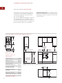
IN STA LL AT ION S P E C I F I C AT I O N S
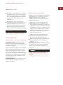
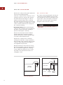
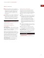
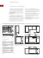
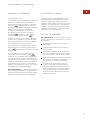
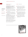
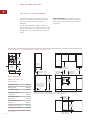
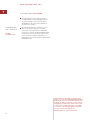
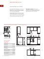
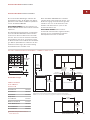
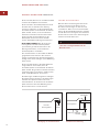
The illustrations below provide the overall
dimensions, countertop cut-out and installation
specifications for Model ICBCT15G.
For Model ICBCT15G, the gas service may be
supplied through the floor if the cooktop is not
installed above an oven. Refer to the illustration
for specifics on placement of gas and electrical.
914 mm
FLOOR TO
COUNTERTOP
762 mm min
COUNTERTOP
TO COMBUSTIBLE
MATERIALS
SEE COUNTERTOP
CUT-OUT BELOW
356 mm
CUT-OUT
WIDTH
COUNTERTOP CUT-OUT
FRONT
489 mm
CUT-OUT
DEPTH
64 mm min
178 mm TO
COMBUSTIBLE*
178 mm TO
COMBUSTIBLE*
SIDE
CABINET
330 mm
max
*Minimum clearance from cooktop cut-out to combustible materials up to 457 mm above countertop.
NOTE: Application shown allows for installation of two 381 mm modules side by side.
E
381 mm
381
mm
102 mm
457 mm min
127
mm
LOCATION OF GAS
AND ELECTRICAL
EXTENDS ON FLOOR
G
64
mm*
W O L F GA S C OOK TOP S
Overall Dimensions
381 mm
OVERALL WIDTH
533 mm
OVERALL
DEPTH
102 mm
M O D E L I C B C T 1 5 G
D I M E N S I O N S
Overall Width 381 mm
Overall Height 102 mm
Overall Depth 533 mm
Recommended
Cabinet Width 838 mm
Minimum Cabinet Depth 578 mm
Minimum Height Clearance 102 mm
Cut-Out Width 356 mm
Cut-Out Depth 489 mm
Unit dimensions may vary to
±
3 mm.
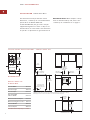
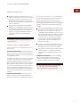
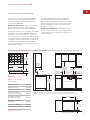
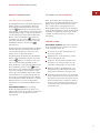
I N S TA L L AT I O N S P E C I F I C AT I O N S – M O D E L I C B C T 1 5 G
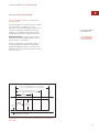
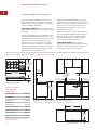
IMPORTANT NOTE:
When multiple cooktop
units are installed side by side, refer to the
countertop cut-out dimensions on page 11.

457 mm min
914 mm
FLOOR TO
COUNTERTOP
762 mm
min
C
OUNTERTOP
TO COMBUSTIBLE
MATERIALS
762 mm OVEN OPENING
102 mm
254 mm
89 mm
E
SEE COUNTERTOP
CUT-OUT BELOW
229 mm TO
COMBUSTIBLE*
229 mm TO
COMBUSTIBLE*
64
mm*
SIDE
CABINET
330 mm
m
ax
737 mm
CUT-OUT WIDTH
COUNTERTOP CUT-OUT
FRONT
489 mm
CUT-OUT
DEPTH
64 mm min
*Minimum clearance from cooktop cut-out to combustible materials up to 457 mm above countertop.
NOTE: Gas and electrical location applies only to installation with built-in oven.
G
9
IN STA LL AT ION I N S T R U C T I O N S
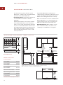
Overall Dimensions
533 mm
FONDO
T
OTAL
762 mm
ANCHURA TOTAL
102 mm
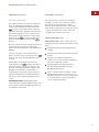
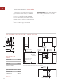
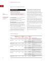
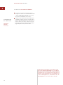
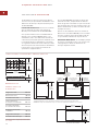
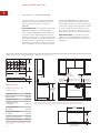
IN STA LL AT ION S P E C I F I C AT I O N S
The illustrations below provide the overall
dimensions, countertop cut-out and installation
specifications for Model ICBCT30G.
IMPORTANT NOTE:
838 mm wide cabinets are
recommended for installation of Model
ICBCT30G.
A Wolf 762 mm single built-in oven may be
installed below Model ICBCT30G. For this
installation, unless you are using cabinets
deeper than 610 mm, it is recommended that
the electrical and gas supply be placed in the
base cabinet to the right of the oven. Refer to
installation instructions provided with the built-
in oven for additional specifications.
If the Model ICBCT30G is installed above
cabinets, the gas and electrical placement is not
critical. A grounded outlet needs to be placed
within 1.2 m of the right rear of the cooktop.
IMPORTANT NOTE:
When multiple cooktop
units are installed side by side, refer to the
countertop cut-out dimensions on page 11.
M O D E L I C B C T 3 0 G
D I M E N S I O N S
Overall Width 762 mm
Overall Height 102 mm
Overall Depth 533 mm
Recommended
Cabinet Width 838 mm
Minimum Cabinet Depth 578 mm
Minimum Height Clearance 102 mm
Cut-Out Width 737 mm
Cut-Out Depth 489 mm
Unit dimensions may vary to
±
3 mm.
I N S TA L L AT I O N S P E C I F I C AT I O N S – M O D E L I C B C T 3 0 G

10
W O L F GA S C OOK TOP S
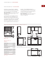
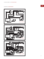
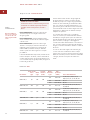
IN STA LL AT ION S P E C I F I C AT I O N S
The illustrations below provide the overall
dimensions, countertop cut-out and installation
specifications for Model ICBCT36G.
IMPORTANT NOTE:
991 mm wide cabinets are
recommended for installation of Model
ICBCT36G.
A Wolf 914 mm built-in oven may be installed
below Model ICBCT36G. For this installation,
unless you are using cabinets deeper than 610
mm, it is recommended that the electrical and
gas supply be placed in the base cabinet to the
right of the oven. Refer to installation instruc-
tions provided with the built-in oven for addi-
tional specifications.
If the Model ICBCT36G is installed above
cabinets, the gas and electrical placement is not
critical. A grounded outlet needs to be placed
within 1.2 m of the right rear of the cooktop.
When a 914 mm built-in oven is installed below
Model ICBCT36G, it is recommended that the
rough opening for the oven be 197 mm from
the floor to ease the use of the oven door.
IMPORTANT NOTE:
When multiple cooktop
units are installed side by side, refer to the
countertop cut-out dimensions on page 11.
102 mm
E
G
457 mm min
914 mm
FLOOR TO
COUNTERTOP
762 mm min
COUNTERTOP
TO COMBUSTIBLE
MATERIALS
914 mm OVEN OPENING
254 mm
89 mm
SEE COUNTERTOP
CUT-OUT BELOW
889 mm
CUT-OUT WIDTH
COUNTERTOP CUT-OUT
FRONT
489 mm
CUT-OUT
DEPTH
64 mm min
229 mm TO
COMBUSTIBLE
*
229 mm TO
COMBUSTIBLE
*
SIDE
CABINET
330 mm
m
ax
*Minimum clearance from cooktop cut-out to combustible materials up to 457 mm above countertop.
NOTE: Gas and electrical location applies only to installation with built-in oven.
64
mm*
Overall Dimensions
533 mm
OVERALL
DEPTH
914 mm
OVERALL WIDTH
102 mm
M O D E L I C B C T 3 6 G
D I M E N S I O N S
Overall Width 914 mm
Overall Height 102 mm
Overall Depth 533 mm
Recommended
Cabinet Width 991 mm
Minimum Cabinet Depth 578 mm
Minimum Height Clearance 102 mm
Cut-Out Width 889 mm
Cut-Out Depth 489 mm
Unit dimensions may vary to
±
3 mm.
I N S TA L L AT I O N S P E C I F I C AT I O N S – M O D E L I C B C T 3 6 G

11
IN STA LL AT ION I N S T R U C T I O N S
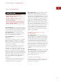
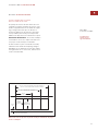
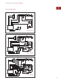
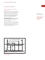
IN STA LL AT ION O P T I O N S
M U LT I P L E C O O K T O P I N S TA L L AT I O N
If the gas cooktop is to be used with any
combination of additional cooktop units or
modules with a filler strip, the cut-out width is
calculated by adding the corresponding units'
cut-out dimensions plus 32 mm for each addi-
tional unit. Refer to the illustration below.
IMPORTANT NOTE:
When multiple units are
installed side by side, each unit must have its
own separate recommended electrical circuit.
When two or more modules are installed
together, an integrated module filler strip
(IFILLER/S) is recommended. Contact your
Wolf dealer for information on these accessory
components.
64 mm
min
FRONT OF COUNTERTOP
489 mm
CUT-OUT
DEPTH
743 mm
TWO MODULES WIDTH
1130 mm – THREE MODULES WIDTH OR
1124 mm – 762 mm COOKTOP AND ONE MODULE
1518 mm – FOUR MODULES WIDTH OR
1511 mm – 762 mm COOKTOP AND TWO MODULES OR
1276 mm – 914 mm COOKTOP AND ONE MODULE
356 mm
CUT-OUT
WIDTH
Countertop cut-out dimensions for installation of multiple cooktops
O
P T I O N A L
I N S TA L L AT I O N S
Dimensions will
vary according to
the specific installa-
tion.

12
W O L F GA S C OOK TOP S
IMPORTANT NOTE:
The gas cooktop must be
connected to a regulated gas supply.
IMPORTANT NOTE:
This installation must
conform with local codes and ordinances.
IMPORTANT NOTE:
The natural gas cooktop
is rated for elevations up to 2438 m without
adjustment. Install a high altitude kit for eleva-
tions from 2438 to 3084 m. The LP gas cooktop
is rated for 3084 m.
The rating plate, located on the underside of
the burner box, has information on the type of
gas that should be used. If this information
does not agree with the type of gas available,
check with the local gas supplier.
EXPLOSION HAZARD—
Securely tighten all external gas
connections.
Failure to do so can result in explosion,
fire or death.
GA S S UP PLY R E Q U I R E M E N T S
Provide a gas supply line of 19 mm rigid pipe
to the cooktop location. A smaller size pipe on
long runs may result in insufficient gas supply.
Pipe joint compounds, suitable for use with LP
gas should be used. For LP gas, piping or
tubing size can be 13 mm minimum. LP gas
suppliers usually determine the size and mate-
rials used on the system.
If local codes permit, a flexible metal appliance
connector is recommended for connecting this
cooktop to the gas supply line. Do not kink or
damage the flexible connector when moving
the cooktop. You will need to determine the
fittings required, depending on the size of your
gas supply line, flexible metal connector and
shut-off valve.
If rigid pipe is used as a gas supply line, a
combination of pipe fittings must be used to
obtain an in-line connection to the cooktop. All
strains must be removed from the supply and
gas lines so the cooktop will be level and in
line.
I
M P O RTA N T
N OT E
This installation
must conform with
local codes and
ordinances.
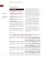
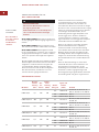
GA S R AT I N G
Total Heat Electrical Types and
Output Gas Rating Appliance Pressures
Model # (Gas) Units (Watts) Category (mbar) Country of Destination
I2H G20 at 20
AT, DK, EE, FI, GR, IE, IT, LT,
ICBCT15G/S 6.8 kW 230
NO, PT, ES, SE, SI, SK, GB, CH
I2E G20 at 20 DE, PL
I2E+ G20 at 20/25 BE, FR
ICBCT15G/S-LP 494 g/h 230 I3P G31 at 37
BE, CZ, FR, GR, IE, NL, NO, PT,
ES, GB, CH
I2H G20 at 20
AT, DK, EE, FI, GR, IE, IT, LT,
ICBCT30G/S 14.7 kW 230
NO, PT, ES, SE, SI, SK, GB, CH
I2E G20 at 20 DE, PL
I2E+ G20 at 20/25 BE, FR
ICBCT30G/S-LP 1069 g/h 230 I3P G31 at 37
BE, CZ, FR, GR, IE, NL, NO, PT,
ES, GB, CH
I2H G20 at 20
AT, DK, EE, FI, GR, IE, IT, LT,
ICBCT36G/S 17.7 kW 230
NO, PT, ES, SE, SI, SK, GB, CH
I2E G20 at 20 DE, PL
I2E+ G20 at 20/25 BE, FR
ICBCT36G/S-LP 1287 g/h 230 I3P G31 at 37
BE, CZ, FR, GR, IE, NL, NO, PT,
ES, GB, CH

13
IN STA LL AT ION I N S T R U C T I O N S
EL ECT RI CA L R E Q U I R E M E N T S
ELECTRICAL SHOCK HAZARD—
Plug into a grounded 3-prong adapter.
Do not remove ground prong.
D
o not use an adapter.
Failure to follow these instructions can
result in electric shock, fire or death.
IMPORTANT NOTE:
Connection of this appli-
ance should be through a fused connection
unit or a suitable isolator, which complies with
national and local safety regulations. The
on/off switch should be easily accessible after
the appliance has been installed. If the switch
is not accessible after installation (depending
on country) an additional means of disconnec-
tion must be provided for all poles of the
power supply. When switched off there must
be an all pole contact gap of 3 mm in the
isolator switch. This 3 mm contact disconnect
gap must apply to any isolator switch, fuses
and/or relays according to EN60335.
R E C O M M E N D E D G R O U N D M E T H O D
IMPORTANT NOTE:
For your personal safety,
this cooktop must be grounded. This cooktop
is equipped with a 3-prong ground plug. To
minimize possible shock hazard, a 85C
minimum rated cord must be plugged into a
mating 3-prong ground-type outlet, grounded
in conformance with all local codes and ordi-
nances. If a mating outlet is not available, it is
the obligation of the customer to have a
properly grounded, 3-prong outlet installed by
a qualified electrician.
IMPORTANT NOTE:
If product is connected to
a GFCI protected outlet, nuisance tripping of
power supply may occur, resulting in loss of
product operation.
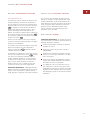
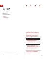
W I R I N G D I A G R A M
A wiring diagram covering the control circuit
for each Wolf gas cooktop model can be found
on page 17.
IMPORTANT NOTE:
If codes permit and a
separate ground wire is used, it is recom-
mended that a qualified electrician determine
that the ground path is adequate.
IMPORTANT NOTE:
Check with a qualified
electrician if you are not sure whether the
cooktop is properly grounded.
IMPORTANT NOTE:
Do not ground to a gas
pipe.
A 220-240 V AC, 50/60 Hz, fused electrical
supply is required. A time-delay fuse or circuit
breaker is recommended. It is recommended
that a separate circuit serving only this appli-
ance be provided.
Electronic ignition systems operate within
wide voltage limits, but proper ground and
polarity are necessary. In addition to checking
that the outlet provides 220-240 V AC power
and is correctly grounded, the outlet must be
checked by a qualified electrician to see if it is
wired with correct polarity. A wiring diagram is
provided in the literature package.
This appliance, when installed, must be electri-
cally grounded in accordance with local codes.

14
C O O K T O P IN STA LL ATI ON
Remove the cooktop, burner grates and burner
caps from the shipping package.
Lower the cooktop into the countertop cut-out
opening. Center the cooktop in the opening
and check that the front edge of cooktop is
parallel to the front edge of the countertop.
Check that all required clearances are met. Use
a pencil to outline the rear edge of the cooktop
on the countertop. Remove the cooktop from
the countertop opening.
IMPORTANT NOTE:
When repositioning the
cooktop in the countertop cut-out opening, lift
the entire cooktop up from the opening to
prevent scratching the countertop.
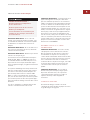
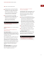
Remove the foam strip from the hardware
package. Apply the foam strip around the
bottom of the burner box flush with the edge
as shown in the illustration below.
Reinsert the cooktop into the countertop
opening. Check that the cooktop is parallel to
the front edge of the countertop. Lift the entire
cooktop to make adjustments and align the
rear edge with the pencil line.
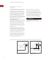
Attach the brackets to the burner box. Insert
the 89 mm clamping screws into the brackets.
Use a screwdriver to tighten the clamping
screws against the underside of the counter-
top. Refer to the illustration below. Do not
overtighten screws.
G A S L E A K T E S T I N G
Use a brush and liquid detergent to test all gas
connections for leaks. Bubbles around connec-
tions will indicate a leak. If a leak appears, shut
off gas valve controls and adjust connections.
Then check connections again. Clean all the
detergent solution from the cooktop.
Cooktop
Burner Box
Foam
Strip
Foam strip application
W O L F GA S C OOK TOP S
89 mm
Clamping
Screw
Burner Box
Countertop
Bracket
Screws
Bracket
Bracket installation
Never test for a gas leak with a match or
other flame.

15
IN STA LL AT ION I N S T R U C T I O N S
SU RFACE B U R N E R S
I N I T I A L L I G H T I N G
The surface burners use electronic igniters in
place of standing pilots. When the cooktop
control knob is pushed in and turned to the
position, the system creates a spark to
light the burner. This sparking continues until
the electronic ignition senses a flame. If the
burner fails to ignite after 10 seconds, return
the knob to the position and attempt to
ignite by turning the knob back to the
position.
Be sure to place the burner heads and caps on
each burner base and position the burner
grates over the burner bases and heads before
lighting.
To check operation of the surface burners,
push in and turn each control knob to the
position. The flame should light within four
seconds.
If the burners do not light properly, turn
control knob to the position. Check that
the burner heads and caps are in the proper
position. Check that the power supply cord is
plugged in and that the circuit breaker or
house fuse has not blown. Check operation
again, if the burners do not light properly at
this point, contact a Wolf authorized service
center.
IMPORTANT NOTE:
Initial lighting of the
surface burners may take slightly longer, as air
in the system must be purged before gas can
be supplied to the burner.
CO OKTOP R E M O VA L
If it is necessary to remove the cooktop for
cleaning or service, shut off the gas supply.
Disconnect the gas and electric supply.
Remove the mounting brackets on the right
and left side of the burner box and remove the
cooktop. Reinstall in the reverse order and
check the gas connection for leaks.
TRO UB LES H O OT I N G
IMPORTANT NOTE:
If the cooktop does not
operate properly, follow these troubleshooting
steps:
Verify that power is being supplied to the
cooktop.
Check that gas valves are turned to the ON
position.
Check the gas supply and electrical
connections to ensure that the installation
has been completed correctly.
Follow troubleshooting procedures as
described in the Wolf Gas Cooktops
Use & Care Information.
If the cooktop still does not work, contact
a Wolf authorized service center. Do not
attempt to repair the cooktop yourself. Wolf
is not responsible for service required to
correct a faulty installation.

16
C O N TA C T
I N F O R M AT I O N
Website:
wolfappliance.com
W O L F GA S C OOK TOP S
I F YO U N E E D SE RVI CE
For service in your area, contact either your
Wolf dealer or visit the Showroom Locator
section of our website, wolfappliance.com
to find the regional distributor by country.
When calling for service, you will need the
cooktop model and serial numbers. Both
numbers are listed on the rating plate,
located on the underside of the cooktop.
Refer to the illustration on page 6 for
location of the rating plate.
The information and images in this book are the
copyright property of Wolf Appliance, Inc., an affili-
ate of Sub-Zero, Inc. Neither this book nor any
information or images contained herein may be
copied or used in whole or in part without the
express written permission of Wolf Appliance,
Inc.,an affiliate of Sub-Zero, Inc.
©Wolf Appliance, Inc. all rights reserved.

17
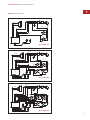
IN STA LL AT ION I N S T R U C T I O N S
P
OWER CORD
FRONT
R
IV
GAS VALVE
RED
RED
B
LACK
WHITE
G
RN/YEL
B
LACK
REAR
BLACK
BLACK
WHITE
WHITE
Model ICBCT15G
POWER CORD
WHITE
RIGHT
FRONT
BLACK
RIV
GAS VALVE
RED
RED
RED
RED
WHITE
GRN/YEL
B
LACK
RIGHT
REAR
LEFT
REAR
LEFT FRONT
B
LACK
WHITE
WHITE
BLACK
LEFT FRONT
POWER CORD
RED
RIV
GAS VALVE
WHITE
BLACK
RIGHT
REAR
LEFT REAR
RIGHT
FRONT
CTR REAR
GRN/YEL
BLACK
RED
RED
RED
BLACK
WHITE
WI RIN G D I A G R A M S
Model ICBCT30G
Model ICBCT36G
Page is loading ...
Page is loading ...
Page is loading ...
Page is loading ...
Page is loading ...
Page is loading ...
Page is loading ...
Page is loading ...
Page is loading ...
Page is loading ...
Page is loading ...
Page is loading ...
Page is loading ...

31
I N S T R U C C I O N E S D E INSTA L AC I Ó N
CABLE ELÉCTRICO
DELANTERO
RIV
(REENCENDIDO
C
ON CONTROL
DE VÁLVULA DEL
ENCENDEDOR)
VÁLVULA DE GAS
ROJO
ROJO
NEGRO
BLANCO
VERDE/AMARILLO
NEGRO
TRASERO
NEGRO
NEGRO
BLANCO
BLANCO
M
odelo ICBCT15G
CABLE ELÉCTRICO
BLANCO
DELANTERO
DERECHO
NEGRO
VÁLVULA DE GAS
ROJO
R
OJO
ROJO
R
OJO
BLANCO
VERDE/AMARILLO
NEGRO
TRASERO
DERECHO
TRASERO
IZQUIERDO
DELANTERO IZQUIERDO
NEGRO
BLANCO
RIV
(REENCENDIDO
CON CONTROL
DE VÁLVULA DEL
ENCENDEDOR)
BLANCO
NEGRO
DELANTERO IZQUIERDO
CABLE ELÉCTRICO
ROJO
VÁLVULA DE GAS
BLANCO
NEGRO
TRASERO
DERECHO
TRASERO IZQUIERDO
DELANTERO
DERECHO
CENTRAL TRASERO
VERDE/AMARILLO
NEGRO
ROJO
ROJO
ROJO
NEGRO
BLANCO
RIV
(REENCENDIDO
CON CONTROL
DE VÁLVULA DEL
ENCENDEDOR)
C U A D RO D E C O N E X IO N E S
Modelo ICBCT30G
Modelo ICBCT36G
Page is loading ...
Page is loading ...
Page is loading ...
Page is loading ...
Page is loading ...
Page is loading ...
Page is loading ...
Page is loading ...
Page is loading ...
Page is loading ...
Page is loading ...
Page is loading ...
Page is loading ...

45
I N S T R U C T I O N S D ’ I N S TA L L ATION
CORDON ELECTRIQUE
AVANT
ROBINET DU GAZ
ROUGE
ROUGE
NOIR
BLANC
VERT/JAUNE
NOIR
ARRIERE
NOIR
NOIR
BLANC
BLANC
RALLUMAGE AVEC
COM. DE VALVE
D’ALLUMEUR
M
odèle ICBCT15G
CORDON ELECTRIQUE
BLANC
AVANT
DROIT
NOIR
ROBINET DU GAZ
ROUGE
ROUGE
ROUGE
ROUGE
BLANC
VERT/JAUNE
NOIR
ARRIERE
DROIT
ARRIERE
GAUCHE
AVANT GAUCHE
NOIR
BLANC
RALLUMAGE AVEC
COM. DE VALVE
D’ALLUMEUR
BLANC
NOIR
AVANT GAUCHE
CORDON ELECTRIQUE
ROUGE
RALLUMAGE AVEC
COM. DE VALVE
D’ALLUMEUR
ROBINET DU GAZ
BLANC
NOIR
ARRIERE
DROIT
ARRIERE GAUCHE
AVANT
DROIT
ARRIERE CENTRE
VERT/JAUNE
NOIR
ROUGE
ROUGE
ROUGE
NOIR
BLANC
S C H E M A S D E CA B L AG E
Modèle ICBCT30G
Modèle ICBCT36G
Page is loading ...
Page is loading ...
Page is loading ...
Page is loading ...
Page is loading ...
Page is loading ...
Page is loading ...
Page is loading ...
Page is loading ...
Page is loading ...
Page is loading ...
Page is loading ...
Page is loading ...

59
I S T R U Z I O N I P E R L’INS TA LL A Z I O N E
CAVO DI ALIMENTAZIONE
PARTE ANTERIORE
RIACC.
VALVOLA DEL GAS
ROSSO
ROSSO
NERO
BIANCO
VERDE/GIALLO
NERO
P
OSTERIORE
NERO
NERO
BIANCO
BIANCO
M
odello ICBCT15G
CAVO DI ALIMENTAZIONE
BIANCO
NERO
RIACC.
VALVOLA DEL GAS
ROSSO
ROSSO
ROSSO
ROSSO
BIANCO
VERDE/GIALLO
NERO
POSTERIORE
SINISTRO
ANTERIORE SINISTRO
NERO
BIANCO
POSTERIORE
DESTRO
ANTERIORE
DESTRO
BIANCO
NERO
CAVO DI ALIMENTAZIONE
ROSSO
RIACC.
VALVOLA DEL GAS
BIANCO
NERO
CENTRALE
POSTERIORE
VERDE/GIALLO
NERO
ROSSO
ROSSO
ROSSO
NERO
BIANCO
POSTERIORE
DESTRO
ANTERIORE
DESTRO
ANTERIORE SINISTRO
POSTERIORE
SINISTRO
S C H E M A EL E TT R I C O
Modello ICBCT30G
Modello ICBCT36G
Page is loading ...
Page is loading ...
Page is loading ...
Page is loading ...
Page is loading ...
Page is loading ...
Page is loading ...
Page is loading ...
Page is loading ...
Page is loading ...
Page is loading ...
Page is loading ...
Page is loading ...
Page is loading ...
Page is loading ...
Page is loading ...

WOLF APPLIANCE, INC.
PO BOX 44848
MADISON, WI 53744 USA
WOLFAPPLIANCE.COM
8 1 0 1 2 7 R E V- C 2 / 2 0 1 3
-
 1
1
-
 2
2
-
 3
3
-
 4
4
-
 5
5
-
 6
6
-
 7
7
-
 8
8
-
 9
9
-
 10
10
-
 11
11
-
 12
12
-
 13
13
-
 14
14
-
 15
15
-
 16
16
-
 17
17
-
 18
18
-
 19
19
-
 20
20
-
 21
21
-
 22
22
-
 23
23
-
 24
24
-
 25
25
-
 26
26
-
 27
27
-
 28
28
-
 29
29
-
 30
30
-
 31
31
-
 32
32
-
 33
33
-
 34
34
-
 35
35
-
 36
36
-
 37
37
-
 38
38
-
 39
39
-
 40
40
-
 41
41
-
 42
42
-
 43
43
-
 44
44
-
 45
45
-
 46
46
-
 47
47
-
 48
48
-
 49
49
-
 50
50
-
 51
51
-
 52
52
-
 53
53
-
 54
54
-
 55
55
-
 56
56
-
 57
57
-
 58
58
-
 59
59
-
 60
60
-
 61
61
-
 62
62
-
 63
63
-
 64
64
-
 65
65
-
 66
66
-
 67
67
-
 68
68
-
 69
69
-
 70
70
-
 71
71
-
 72
72
-
 73
73
-
 74
74
-
 75
75
-
 76
76


Wolf ICBCT30G/S Installation Instructions Manual
- Type
- Installation Instructions Manual
- This manual is also suitable for
Ask a question and I''ll find the answer in the document
Finding information in a document is now easier with AI
in other languages
- italiano: Wolf ICBCT30G/S
- français: Wolf ICBCT30G/S
- español: Wolf ICBCT30G/S
- Deutsch: Wolf ICBCT30G/S
Related papers
-
Wolf ICBCT15G Installation Instructions Manual
-
-
-
-
Wolf CT15I/S Specification
-
Wolf ICBDD30R Specification
-
-
Sub-Zero ICBCT30G User manual
-
Wolf Appliance Company ICBIG15/S User manual
-