Powermatic OES9138 Sander, 3HP 3PH 230/460V User manual
- Category
- Power sanders
- Type
- User manual

Operating Instructions and Parts Manual
Oscillating Edge Sander
Model OES9138
WMH TOOL GROUP
2420 Vantage Drive
Elgin, Illinois 60123 Part No. M-0460268
Ph.: 800-274-6848 Revision C 4/04
www.wmhtoolgroup.com Copyright © WMH Tool Group

2
This manual has been prepared for the owner and operators of a Powermatic OES9138 Oscillating Edge
Sander. Its purpose, aside from machine operation, is to promote safety using accepted operating and
maintenance procedures. To obtain maximum life and efficiency from your edge sander and to aid in
using it safely, please read this manual thoroughly and follow the instructions carefully.
Warranty and Service
WMH Tool Group warrants every product it sells. If one of our tools needs service or repair, one of our
Authorized Repair Stations located throughout the United States can provide quick service or information.
In most cases, a WMH Tool Group Repair Station can assist in authorizing repair work, obtaining parts, or
perform routine or major maintenance repair on your Powermatic product.
For the name of an Authorized Repair Station in your area, please call 1-800-274-6848, or visit our web
site at www.wmhtoolgroup.com
More Information
Remember, WMH Tool Group is consistently adding new products to the line. For complete, up-to-date
product information, check with your local WMH Tool Group distributor, or visit our web site at
www.wmhtoolgroup.com
WMH Tool Group Warranty
WMH Tool Group makes every effort to assure that its products meet high quality and durability standards
and warrants to the original retail consumer/purchaser of our products that each product be free from
defects in materials and workmanship as follows: 1 YEAR LIMITED WARRANTY ON ALL PRODUCTS
UNLESS SPECIFIED OTHERWISE. This Warranty does not apply to defects due directly or indirectly to
misuse, abuse, negligence or accidents, normal wear-and-tear, repair or alterations outside our facilities,
or to a lack of maintenance.
WMH TOOL GROUP LIMITS ALL IMPLIED WARRANTIES TO THE PERIOD SPECIFIED ABOVE,
BEGINNING FROM THE DATE THE PRODUCT WAS PURCHASED AT RETAIL. EXCEPT AS STATED
HEREIN, ANY IMPLIED WARRANTIES OR MERCHANTABILITY AND FITNESS ARE EXCLUDED.
SOME STATES DO NOT ALLOW LIMITATIONS ON HOW LONG THE IMPLIED WARRANTY LASTS,
SO THE ABOVE LIMITATION MAY NOT APPLY TO YOU. IN NO EVENT SHALL WMH TOOL GROUP
BE LIABLE FOR DEATH, INJURIES TO PERSONS OR PROPERTY, OR FOR INCIDENTAL,
CONTINGENT, SPECIAL, OR CONSEQUENTIAL DAMAGES ARISING FROM THE USE OF OUR
PRODUCTS. SOME STATES DO NOT ALLOW THE EXCLUSION OR LIMITATION OF INCIDENTAL
OR CONSEQUENTIAL DAMAGES, SO THE ABOVE LIMITATION OR EXCLUSION MAY NOT APPLY
TO YOU.
To take advantage of this warranty, the product or part must be returned for examination, postage
prepaid, to an Authorized Repair Station designated by our office. Proof of purchase date and an
explanation of the complaint must accompany the merchandise. If our inspection discloses a defect, we
will either repair or replace the product at our discretion, or refund the purchase price if we cannot readily
and quickly provide a repair or replacement. We will return the repaired product or replacement at WMH
Tool Group’s expense, but if it is determined there is no defect, or that the defect resulted from causes
not within the scope of WMH Tool Group’s warranty, then the user must bear the cost of storing and
returning the product. This warranty gives you specific legal rights; you may also have other rights, which
vary from state to state.
WMH Tool Group sells through distributors only. Members of the WMH Tool Group reserve the right to
effect at any time, without prior notice, alterations to parts, fittings and accessory equipment, which they
may deem necessary for any reason whatsoever.

3
Table of Contents
Warranty and Service ..............................................................................................................................2
Warning...................................................................................................................................................4
Introduction..............................................................................................................................................6
Specifications ..........................................................................................................................................6
Features of the OES9138 Edge Sander...................................................................................................7
Unpacking ...............................................................................................................................................8
Contents of the Shipping Container......................................................................................................8
Assembly.................................................................................................................................................8
Control Switch Bracket.........................................................................................................................9
Dust Collection.....................................................................................................................................9
Grounding Instructions.............................................................................................................................9
230 Volt Operation .............................................................................................................................10
Test Run After Wiring.........................................................................................................................11
Converting to 460 Volt........................................................................................................................11
Extension cords..................................................................................................................................11
Adjustments...........................................................................................................................................11
Main Table Positioning.......................................................................................................................11
Main Table Tilting...............................................................................................................................12
Table/Belt Clearance..........................................................................................................................12
Miter Gauge.......................................................................................................................................12
End Table..........................................................................................................................................12
End Guard..........................................................................................................................................13
Replacing Sanding Belt......................................................................................................................13
Tracking Adjustment...........................................................................................................................13
Operating Controls.................................................................................................................................14
Operation...............................................................................................................................................14
Maintenance..........................................................................................................................................15
Lubrication .........................................................................................................................................15
Optional Accessories .............................................................................................................................19
Replacement Parts................................................................................................................................19
Parts List: Base Assembly..................................................................................................................20
Base Assembly ..................................................................................................................................21
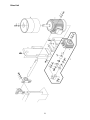
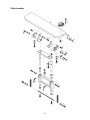
Parts List: Drive Unit...........................................................................................................................22
Drive Unit...........................................................................................................................................23
Parts List: Tracking and Belt Release Unit..........................................................................................24
Tracking and Belt Release Unit ..........................................................................................................25
Parts List: Table Assembly.................................................................................................................26
Table Assembly..................................................................................................................................27
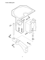
Parts List: Contour Sanding Unit.........................................................................................................28
Contour Sanding Unit.........................................................................................................................29
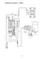
Electrical Connections – 1 Phase...........................................................................................................30
Electrical Connections – 3 Phase...........................................................................................................31

4
Warning
1. Read and understand the entire owners manual before attempting assembly or operation.
2. Read and understand the warnings posted on the machine and in this manual. Failure to comply with
all of these warnings may cause serious injury.
3. Replace the warning labels if they become obscured or removed.
4. This edge sander is designed and intended for use by properly trained and experienced personnel
only. If you are not familiar with the proper and safe operation of an edge sander, do not use until
proper training and knowledge have been obtained.
5. Do not use this edge sander for other than its intended use. If used for other purposes, WMH Tool
Group disclaims any real or implied warranty and holds itself harmless from any injury that may result
from that use.
6. Always wear approved safety glasses/face shields while using this edge sander. Everyday
eyeglasses only have impact resistant lenses; they are not safety glasses.
7. Before operating this edge sander, remove tie, rings, watches and other jewelry, and roll sleeves up
past the elbows. Remove all loose clothing and confine long hair. Non-slip footwear or anti-skid floor
strips are recommended. Do not wear gloves.
8. Wear ear protectors (plugs or muffs) during extended periods of operation.
9. Some dust created by power sanding, sawing, grinding, drilling and other construction activities
contain chemicals known to cause cancer, birth defects or other reproductive harm. Some examples
of these chemicals are:
• Lead from lead based paint.
• Crystalline silica from bricks, cement and other masonry products.
• Arsenic and chromium from chemically treated lumber.
Your risk of exposure varies, depending on how often you do this type of work. To reduce your
exposure to these chemicals, work in a well-ventilated area and work with approved safety
equipment, such as face or dust masks that are specifically designed to filter out microscopic
particles.
10. Do not operate this machine while tired or under the influence of drugs, alcohol or any medication.
11. Make certain the switch is in the OFF position before connecting the machine to the power supply.
12. Make certain the machine is properly grounded.
13. Make all machine adjustments or maintenance with the machine unplugged from the power source.
14. Remove adjusting keys and wrenches. Form a habit of checking to see that keys and adjusting
wrenches are removed from the machine before turning it on.
15. Keep safety guards in place at all times when the machine is in use. If removed for maintenance
purposes, use extreme caution and replace the guards immediately.
16. Check damaged parts. Before further use of the machine, a guard or other part that is damaged
should be carefully checked to determine that it will operate properly and perform its intended
function. Check for alignment of moving parts, binding of moving parts, breakage of parts, mounting
and any other conditions that may affect its operation. A guard or other part that is damaged should
be properly repaired or replaced.
17. Provide for adequate space surrounding work area and non-glare, overhead lighting.
18. Keep the floor around the machine clean and free of scrap material, oil and grease.
19. Keep visitors a safe distance from the work area. Keep children away.

5
blahblahblah
20. Make your workshop child proof with padlocks, master switches or by removing starter keys.
21. Give your work undivided attention. Looking around, carrying on a conversation and “horse-play” are
careless acts that can result in serious injury.
22. Maintain a balanced stance at all times so that you do not fall or lean against the sanding belt or other
moving parts. Do not overreach or use excessive force to perform any machine operation.
23. Use the right tool at the correct speed and feed rate. Do not force a tool or attachment to do a job for
which it was not designed. The right tool will do the job better and safer.
24. Use recommended accessories; improper accessories may be hazardous.
25. Make sure the work piece is stabilized during operation. Use the miter gauge whenever possible.
26. Turn off the machine before cleaning. Use a brush or compressed air to remove chips or debris — do
not use your hands.
27. Do not stand on the machine. Serious injury could occur if the machine tips over.
28. Never leave the machine running unattended. Turn the power off and do not leave the machine until it
comes to a complete stop.
29. Remove loose items and unnecessary work pieces from the area before starting the machine.
Familiarize yourself with the following safety notices used in this manual:
This means that if precautions are not heeded, it may result in minor injury and/or
possible machine damage.
This means that if precautions are not heeded, it may result in serious injury or possibly
even death.
- - SAVE THESE INSTRUCTIONS - -

6
Introduction
This manual is provided by Powermatic covering the safe operation and maintenance procedures for a
Model OES9138 Oscillating Edge Sander. This manual contains instructions on installation, safety
precautions, general operating procedures, maintenance instructions and parts breakdown. This machine
has been designed and constructed to provide years of trouble free operation if used in accordance with
instructions set forth in this manual. If there are any questions or comments, please contact either your
local supplier or WMH Tool Group. WMH Tool Group can also be reached at our web site:
www.wmhtoolgroup.com.
Specifications
Model Number.......................................................OES9138.....................................................OES9138
Stock Number..........................................................1791282...................................................... 1791293
Motor ..........................................................3HP, 1Ph, 230V.............3HP, 3Ph, 230/460V (prewired 230)
Electrical Controls............................................24V magnetic.............................................. 24V magnetic
Belt Size (in.).......................................................9 x 138-3/4.................................................. 9 x 138-3/4
Platen Size (in.).....................................................9-1/2 x 48.................................................... 9-1/2 x 48
Table Working Height (in.) ............................34-1/2 to 40-3/4........................................... 34-1/2 to 40-3/4
Main Table Size (L x W) (in.)................................48 x 11-3/4.................................................. 48 x 11-3/4
Main Table Tilt (deg.).....................................5 in and 45 out.............................................5 in and 45 out
End Table Size (in.)................................................18 radius......................................................18 radius
End Table Tilt (deg.) ....................................40 in and 45 out...........................................40 in and 45 out
Belt Speed (FPM)........................................................ 3,542...........................................................3,542
Oscillations per Minute......................................................24................................................................24
Drum Diameter (in.)................................4 Outboard, 9 Drive..................................... 4 Outboard, 9 Drive
Dust Connection Diameter - Two (in.) .................................4..................................................................4
Dust Collection Minimum CFM Required...................... 1,100...........................................................1,100
Overall Dimensions (L x W x H) (in.) ..................83 x 32 x 50.................................................83 x 32 x 50
Shipping Dimensions (L x W x H) (in.)..........86 x 27 x 44-1/2...........................................86 x 27 x 44-1/2
Weight Shipping/Net (lbs.) ....................................... 870/800....................................................... 870/800
The above specifications were current at the time this manual was published, but because of our policy of
continuous improvement, WMH Tool Group reserves the right to change specifications at any time and
without prior notice, without incurring obligations.

7
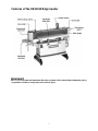
Features of the OES9138 Edge Sander
Read and understand the entire contents of this manual before attempting set-up
or operation! Failure to comply may cause serious injury.

8
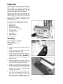
Unpacking
Open shipping container and check for shipping
damage. Report any damage immediately to
your distributor and shipping agent. Do not
discard any shipping material until the Edge
Sander is assembled and running properly.
Compare the contents of your container with the
following parts list to make sure all parts are
intact. Missing parts, if any, should be reported
to your distributor. Read the instruction manual
thoroughly for assembly, maintenance and
safety instructions.
Contents of the Shipping Container
1 Edge Sander
2 Mounting Feet
4 Rubber Foot Pads
1 Control Switch Bracket
4 Hex Cap Screws, M10 x 30
4 Lock Nuts, M10
4 Flat Washers, M10
2 Hand Knobs
1 Owner's Manual
1 Warranty Card
Assembly
Tools required for assembly:
4mm hex wrench
14mm and 17mm wrenches
screwdriver
1. Remove all wood crating from around the
sander.
2. Use a 14mm wrench to remove the screws
holding the sander to the skid.
3. Lift the machine from the skid with a hoist or
forklift by attaching straps to the eyebolts on
top the sander. See Figure 1. DO NOT fork
beneath the main table, or damage to the
table may occur.
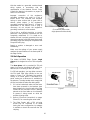
4. Install two rubber feet onto each cast iron
leg. See Figure 2. Screw the feet all the way
in so they are all level with one another.
5. Orient the mounting feet beneath the
machine so that the double holes are toward
the back. See Figure 3. Carefully lower the
sander until it touches the mounting feet,
and align the four holes.
6. Insert the four M10 x 30 screws, against the
four M10 lock washers and M10 flat
washers, through the flange on the machine
base, and into the threaded holes in the
legs. Tighten securely with a 17mm wrench.
Figure 1
Figure 2
Figure 3

9
7. The Edge Sander should be located in a
dry, well-lighted area, on a solid and level
surface, preferably a concrete floor. Leave
plenty of space around the machine for
operations and routine maintenance work.
8. Exposed metal areas of the Edge Sander
have been factory coated with a protectant.
This should be removed with a soft cloth
dampened with kerosene or mineral spirits.
Do not use an abrasive pad. Do not let
solvent contact plastic or rubber parts as it
may damage them.
9. Unscrew the two eyebolts from the sander
and replace them with the hand knobs,
shown in Figure 4. Retain the eyebolts for
future use. NOTE: After the mounting feet
have been installed, the machine can be
lifted with a forklift by forking beneath the
base.
Control Switch Bracket
Mount the control switch bracket (A, Figure 5) to
the top of the sander cabinet with a 4mm hex
wrench, using the four socket head button
screws, lock washers and flat washers (B,
Figure 5) that came installed in the threaded
holes.
Dust Collection
The use of a dust collection system is strongly
recommended for this machine. It will help keep
your shop clean as well as minimize any health
risks caused by wood dust. Make sure your dust
collector has a capacity of at least 1100 cubic
feet per minute (CFM).
Connect the intake hoses of your dust collector
to the 4” diameter dust chutes on the Edge
Sander; there is one on each end of the
machine.
Grounding Instructions
Electrical connections must
be made by a qualified electrician in
compliance with all relevant codes. This
machine must be properly grounded to help
prevent electrical shock and possible fatal
injury.
This machine must be grounded. In the event of
a malfunction or breakdown, grounding provides
a path of least resistance for electric current to
reduce the risk of electric shock.
Figure 4
Figure 5

10
Wire the sander to a grounded, metal-enclosed
wiring system in accordance with the
requirements of the National Electric Code.
Consult the electrical schematics on pages 30
and 31 for clarification.
Improper connection of the equipment-
grounding conductor can result in a risk of
electric shock. The conductor with insulation
having an outer surface that is green with or
without yellow stripes, is the equipment-
grounding conductor (see Figure 6). If repair or
replacement of the electric cord or plug is
necessary, do not connect the equipment-
grounding conductor to a live terminal.
Check with a qualified electrician or service
personnel if the grounding instructions are not
completely understood, or if in doubt as to
whether the tool is properly grounded. Use only
three wire extension cords that have three-prong
grounding plugs and three-pole receptacles that
accept the tool’s plug.
Repair or replace a damaged or worn cord
immediately.
Make sure the voltage of your power supply
matches the specifications on the motor plate of
the Edge Sander.
230 Volt Operation
The Model OES9138 Edge Sander single
phase unit is designed to run on 230 volt power
only.
The three phase unit is pre-wired for 230 volt
power, but can be converted to 460 volt if so
desired (see “Converting to 460 Volt” below).
For 230 volt operation, you may either connect a
UL/CSA listed 230V plug (similiar to the one
shown in Figure 7) or “hard-wire” the machine
directly to a control panel. If hard-wired to a
panel, make sure a disconnect is available for
the operator. The edge sander must comply with
all local and national codes after being wired.
1. If it is to be hard-wired, make sure the fuses
have been removed or the breakers have
been tripped in the circuit to which the Edge
Sander will be connected. Place a warning
placard on the fuse holder or circuit breaker
to prevent it being turned on while the
machine is being wired.
2. Refer to “Electrical Connections” on pages
30 and 31, for connecting the motor leads.
3. The Edge Sander with a 230 volt plug
should only be connected to an outlet
having the same configuration. No adapter
is available or should be used with the 230
volt plug.
Figure 6
(3-conductor power cable,
single phase machine shown)
Figure 7

11
Test Run After Wiring
On the three-phase unit, after wiring has been
completed, you should check that the wires are
connected properly:
1. Connect machine to power source and
press the start button (A, Figure 8).
2. The sanding belt should move left to right,
a
s viewed from the front of the machine. If
the sanding belt movement is incorrect,
press the stop button (B, Figure 8) and
disconnect machine from power.
3. Switch any two of the three wires at "R,S,T".
4. Reconnect machine to power source.
Converting to 460 Volt
Refer to the diagram on page 31 for connecting
the motor leads for 460 volt power. If using a
plug, it must be a proper UL/CSA listed 460 volt
plug. The edge sander must comply with all
local and national codes after being wired.
If hard-wiring directly to a control panel, follow
the same safety recommendations mentioned
under “230 Volt Operation.”
Extension cords
An extension cord is not recommended for this
machine, but if one is necessary, make sure the
cord rating is suitable for the amperage listed on
the machine’s motor plate. An undersized cord
will cause a drop in line voltage resulting in loss
of power and overheating.
Use the chart in Figure 9 as a general guide in
choosing the correct size cord. If in doubt, use
the next heavier gauge. The smaller the gauge
number, the heavier the cord.
Adjustments
Main Table Positioning
The main table can be raised or lowered to suit
your workpiece, and is designed on a special
balance mount so that smooth adjustment is
achieved by a simple push or pull on the table.
To adjust, loosen the locking handles (A, Figure
10) and move the table to desired position by
hand, then tighten locking handles (A, Figure
10).
If the table is in low position,
it may spring up suddenly when the locking
handles are loosened.
Figure 8
Recommended Gauges (AWG) of Extension Cords
Extension Cord Length *
Amps
25
feet
50
feet
75
feet
100
feet
150
feet
200
feet
< 5 16 16 16 14 12 12
5 to 8 16 16 14 12 10 NR
8 to 12 14 14 12 10 NR NR
12 to 15 12 12 10 10 NR NR
15 to 20 10 10 10 NR NR NR
21 to 30 10 NR NR NR NR NR
*based on limiting the line voltage drop to 5V at 150% of the
rated amperes.
NR: Not Recommended.
Figure 9
Figure 10

12
Main Table Tilting
The main table can be tilted up to 5
o
in and 45
o
out, to match the angle of your workpiece.
1. Loosen the locking handle (B, Figure 11) on
both sides beneath the table.
2. With the workpiece on the table, swivel the
table into the desired position with the
workpiece, or use the indicator scale (C,
Figure 11).
3. Tighten locking handles (B, Figure 11).
Table/Belt Clearance
The amount of clearance between the main
table and the sanding belt can be adjusted.
Loosen the screws (D, Figure 11) and slide the
table forward or backward. Re-tighten screws
(D, Figure 11).
Miter Gauge
To adjust the miter gauge, loosen the handle (A,
Figure 12). Rotate the miter gauge body until the
desired angle on the scale lines up with the
notch in the pointer (B, Figure 12). Tighten the
handle (A, Figure 12).
To remove the miter gauge from the table:
1. Unscrew and remove the handle (A, Figure
12).
2. Remove the socket head button screws, flat
washers and lock washers (C, Figure 12)
with a hex wrench, and remove the pointer.
3. On the underside of the table, use a
screwdriver to remove the screw (not
shown) that holds the miter gauge body to
the table.
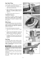
End Table
The end table allows contour sanding. Loosen
the locking handle (A, Figure 13) and swing the
dust hood (B, Figure 13) away from the belt as
shown. In some cases the dust hood may have
to be removed entirely.
If the sanding procedure
requires removal of the dust hood, be sure to
re-install dust hood when finished with that
procedure.
Loosen locking handle (C, Figure 13) to raise or
lower the end table. Tighten locking handle after
adjustment.
Loosen locking handle (D, Figure 14) to tilt the
end table. Tighten locking handle after
adjustment.
Figure 11
Figure 12
Figure 13
Figure 14

13
End Guard
The end guard (A, Figure 15) on the right side of
the machine can be swung out of the way for
sanding long workpieces. (The miter gauge will
need to be removed for such a procedure.)
Loosen the hand knob (B, Figure 15) and swing
open the end guard all the way until it catches
the latch behind it. When finished with the
operation, close the end guard and tighten the
hand knob.
Replacing Sanding Belt
1. Disconnect machine from power source.
2. Swing the end guard (Figure 15) out of the
way, then open the belt guard (C, Figure
16). Also swing the dust hood out of the way
(see Figure 13).
3. Release tension on the belt by pulling the
tension lever (D, Figure 16) all the way up
until it stops against the screw head.
4. Remove the old sanding belt and replace
with the new one.
NOTE: Identify the sanding belt direction
before you install the belt, because the belt's
rotational direction must be the same as the
machine. An arrow on the reverse side of
the belt shows the proper direction. The belt
will move left to right as viewed from the
front of the machine. If the belt has no arrow
indicator, find the joint of the belt (where it is
layered) and install it according to Figure 17.
5. Tension the belt by pushing the lever (A,
Figure 16) all the way down.
6. The sanding belt should now be checked for
tracking. See “Tracking Adjustment.”
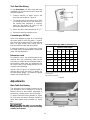
Tracking Adjustment
“Tracking” refers to the position of the sanding
belt on the drums while the sanding belt is in
motion. For proper operation, the sanding belt
should be centered upon the drive drum.
If a new sanding belt has just been installed, the
initial tracking adjustment should be done with
the machine OFF. Rotate the drums by hand
and adjust the tracking mechanism as needed
(see below).
After operating the machine, further minute
adjustments may be needed to the tracking.
This can be done with the machine turned ON
and the sanding belt in motion. Turning the
tracking adjustment knob (B, Figure 18) should
always be done gradually and in small
increments.
Figure 15
Figure 16
Figure 17

14
To adjust tracking, proceed as follows:
1. Loosen the nut (A, Figure 18).
2. Turn the adjustment knob (B, Figure 18)
counter-clockwise to shift the belt upward;
clockwise to shift the belt downward.
3. When the belt is centered and tracking
properly, tighten nut (A, Figure 18).
4. After adjustments are complete, close all
guards.
Operating Controls
Press the start switch (A, Figure 19) to activate
the sanding belt. The stop button (B, Figure 19)
is a mushroom style button which is convenient
for "emergency" shut-downs during operation, if
such should ever be necessary. When re-
starting the sander, twist the knurled ring of the
stop button clockwise to release it.
Operation
Your oscillating belt Edge Sander is designed
and manufactured for long-term operation
creating superior sanded surfaces for wood
products. The oscillation of the belt helps
prevent sanding marks in the workpiece, and
allows longer belt wear.
Before operating the Edge Sander, make sure
all locking handles and knobs are tight on
guards and tables.
Always use the miter gauge, when possible, to
support your workpiece.
This machine is suited for
sanding wood products only. Do not use this
machine for sanding metal products.
Figure 18
Figure 19

15
Maintenance
Before doing maintenance on
the machine, disconnect it from the electrical
supply. Failure to comply may cause serious
injury.
Periodically check both drums. The drums are
made of rubber material and may experience
wear after a long period of use, at which time
they should be replaced.
The sander should be cleaned frequently.
Check all screws, hex nuts, and other fasteners
to make sure they are tight.
Check condition of sanding belt. If belt is worn,
replace it.
If the power cord is worn, cut, or damaged in
any way, have it replaced immediately.
The table should be kept clean and free of rust.
If rust appears on the table, use 000 steel wool
with a paste mixture of household ammonia and
good commercial detergent (or use a
commercial rust remover available from most
hardware and tool supply stores).
Some users coat their table surface with a light
coat of paste wax. (Do not get paste wax on the
sanding belt.) Another option is to apply talcum
powder to the table surface and rub it in briskly
with a clean blackboard eraser. This will also
maintain a slick surface, and will not stain wood.
Lubrication
All ball bearings are sealed for life and do not
require further lubrication.

16
Troubleshooting the OES9138 Edge Sander
Trouble Probable Cause Remedy
Machine not connected to
power source.
Verify machine is connected to power.
Fuse blown, or circuit
breaker tripped.
Replace fuse, or reset circuit breaker.
Cord damaged. Replace cord.
Extension cord too light or
too long.
Use adequate size extension cord.
Overload automatic reset
has not reset.
If the Edge Sander overloads on the circuit breaker
built in to the motor starter, it takes time for the
machine to cool down before restart. Allow unit to
adquately cool before attempting restart. If problem
persists, check amp setting on the motor starter
inside the electrical box.
Edge Sander frequently
trips.
Check the amp setting on the overload relay.
Match the full load amps on the motor as noted on
the motor plate. If amp setting is correct then there
is probably a loose electrical lead or a failed
component. See below.
Building circuit breaker trips
or fuse blows.
Verify that edge sander is on a circuit of correct
size. If circuit size is correct, there is probably a
loose electrical lead. Check amp setting on motor
starter.
Loose electrical
connections.
Go through all the electrical connections on the
edge sander including motor connections, verifying
the tightness of each. Look for any signs of
electrical arcing which is a sure indicator of loose
connection or circuit overload.
Motor starter failure.
If you have access to a voltmeter, you can
separate a starter failure from a motor failure by
first, verifying incoming voltage at 220+/-20 and
second, checking the voltage between starter and
motor at 220+/-20. If incoming voltage is incorrect,
you have a power supply problem. If voltage
between starter and motor is incorrect, you have a
starter problem. If voltage between starter and
motor is correct, you have a motor problem.
Machine will not
start/restart or
repeatedly trips
circuit breakers or
blows fuses.
Motor failure.
If electric motor is suspect, you have two options:
Have a qualified electrician test the motor for
function or remove the motor and take it to a
qualified electric motor repair shop and have it
tested.

17
Trouble Probable Cause Remedy
Miswiring of the unit.
Check to make certain all electrical connections
are correct and properly tight. The electrical
connections other than the motor are
preassembled and tested at the factory. Therefore,
the motor connections should be checked as the
highest probability for error. If problems persist,
double check the factory wiring.
Machine will not
start/restart or
repeatedly trips
circuit breakers or
blows fuses.
On/off switch failure.
If the on/off switch is suspect, you have two
options: Have a qualified electrician test the switch
for function, or purchase a new on/off switch and
establish if that was the problem on changeout.
Extension cord too light or
too long.
Use adequate size extension cord.
Low (incoming) voltage. Contact qualified electrician.
Sanding belt won’t
come up to speed.
Excessive bite, or feed
pressure too great.
Allow sanding belt to cut freely, do not force.
Drum is worn. Replace drum. Belt won’t track.
Belt is stretched unevenly. Replace belt.
Belt slips or stalls
on application of
pressure.
Sanding belt tension not
adequate.
Make sure lever is down all the way (page 13).
Too much pressure being
used during cuts.
Reduce pressure. Excessive sanding
belt replacement.
Not using full width of belt. Stroke across the belt using full width.
Improper motor mounting. Check and adjust mounting.
Spring on tension
mechanism is fatigued or
broken.
Replace with new spring.
Drum is loose. Tighten cap screw in motor (page 23, #39).
Machine vibrates
excessively.
Bad or broken sanding belt. Replace sanding belt.
Sanding belt too coarse for
required finish.
Use proper grit. Coarser grits for stock removal,
and finer grits for finish work.
Sanding marks on
workpiece.
Workpiece sanded across
grain.
When surface sanding, use very fine sanding belt
then finish by hand, working in direction of grain.
Sanding grains
quickly rub off belt.
Sanding belt has lost its
original properties.
Do not store sanding belts in extremely dry or high-
temperature areas. Do not fold sanding belts.
Sanding painted surface. Use open-end grain/flint belt. Sanding belt
becomes glazed.
Wood is wet or gummy. No cure. Use different stock.

18
Trouble Probable Cause Remedy
Wrong sanding belt
surface.
Use coarser grit for stock removal.
Work burns.
Feed pressure too great. Never force workpiece into steel platen. Use just
enough pressure, and let the sanding belt do the
work.
Sanding belt
burns, or clogs
quickly on
thickness sanding.
Biting too deep. Adjust for slight sanding action and make repeated
passes.
Workpiece pulled
from hand.
No support for workpiece. Use miter gauge on table.
Sanding belt has
broken at the joint.
Belt running in wrong
direction.
Orient direction of arrows printed on sanding belt to
match rotation of drums. Sanding belt should move
left to right as viewed from front of machine.
Result of freehand sanding. Keep workpiece flat on table at all times when a
square edge is desired. Use miter gauge.
Sanded edge is
not square.
Table misaligned. Check table alignment to steel platen with a square
or machinist’s protractor. It should be 90 degrees.
Adjust table angle if necessary (page 12).

19
Optional Accessories
6078029 ....Sanding Belt, 60 Grit, 9” x 138-3/4”
6078030 ....Sanding Belt, 80 Grit, 9” x 138-3/4”
6078031 ....Sanding Belt, 100 Grit, 9” x 138-3/4”
6078032 ....Sanding Belt, 120 Grit, 9” x 138-3/4”
6078033 ....Sanding Belt, 150 Grit, 9” x 138-3/4”
6078034 ....Sanding Belt, 180 Grit, 9” x 138-3/4”
6078035 ....Sanding Belt, 220 Grit, 9” x 138-3/4”
Replacement Parts
Replacement parts are listed on the following pages. To order parts or reach our service department, call
1-800-274-6848 between 7:00 a.m. and 6:00 p.m. (CST), Monday through Friday. Having the Model
Number and Serial Number of your machine available when you call will allow us to serve you quickly and
accurately.

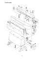
20
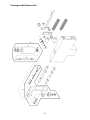
Parts List: Base Assembly
Index No. Part No. Description Size Qty
1...............OES-001................. Machine Base.................................................... ...................................1
2...............OES-002................. Magnetic Motor Starter ...................................... 1Ph, 230V...................1
.................OES-093................. Magnetic Motor Starter ...................................... 3Ph, 230/460V............1
3...............OES-003................. Oscillating Unit Cover........................................ ...................................1
4...............TS-2246082............Socket Head Button Screw................................ M6 x 8........................4
5...............OES-004................. Support Bracket................................................. ...................................1
6...............TS-1550041............Flat Washer....................................................... M6............................15
7...............TS-1551041............Lock Washer......................................................M6............................13
8...............TS-2246162............Socket Head Button Screw................................ M6 x 16....................13
9...............OES-005................. Mounting Foot.................................................... ...................................2
10.............TS-1550071............ Flat Washer....................................................... M10............................8
11.............TS-1551071............ Lock Washer......................................................M10............................8
12.............TS-1491041............ Hex Cap Screw.................................................. M10 x 30.....................4
13.............OES-006................. Rubber Foot Pad ............................................... ...................................4
14.............OES-007................. Platen Casting................................................... ...................................1
17.............TS-2210451............ Hex Cap Screw.................................................. M10 x 45.....................4
18............. ............................... Sanding Belt (also see Optional Accessories, page 19)..........................1
19.............OES-008................. Graphite Pad..................................................... ...................................1
20.............OES-009................. Pad Retaining Plate........................................... ...................................2
21.............TS-1551031............ Lock Washer......................................................M5..............................6
22.............TS-2245162............ Socket Head Button Screw................................M5 x 16......................6
23.............OES-010................. Lt. Sanding Guard Bracket................................. ...................................1
27.............OES-011................. Rt. Sanding Guard Bracket................................ ...................................1
29.............OES-012................. Belt Guard......................................................... ...................................1
33.............OES-013................. Guard Plate....................................................... ...................................1
36.............OES-014................. "U" Handle......................................................... ...................................1
37.............TS-1504031............ Socket Head Cap Screw.................................... M8 x 16 ......................2
38.............TS-1541031............ Nylon Lock Hex Nut........................................... M8..............................2
39.............OES-015................. Hand Knob ........................................................ ...................................2
40.............OES-016................. Lifting Eyebolt.................................................... ...................................2
41.............OES-017................. Switch Arm........................................................ ...................................1
45.............OES-018................. Rubber Pad ....................................................... ...................................4
46.............OES-019................. Start/Stop Switch............................................... ...................................1
47.............OES-094................. Clipper (Female)................................................ ...................................1
48.............OES-095................. Clipper (Male).................................................... ...................................1
49.............TS-2283061............ Phillips Flat Head Machine Screw...................... M3 x 6........................4
50.............OES-096................. Hand Knob ........................................................1/4".............................1
Page is loading ...
Page is loading ...
Page is loading ...
Page is loading ...
Page is loading ...
Page is loading ...
Page is loading ...
Page is loading ...
Page is loading ...
Page is loading ...
Page is loading ...
Page is loading ...
-
 1
1
-
 2
2
-
 3
3
-
 4
4
-
 5
5
-
 6
6
-
 7
7
-
 8
8
-
 9
9
-
 10
10
-
 11
11
-
 12
12
-
 13
13
-
 14
14
-
 15
15
-
 16
16
-
 17
17
-
 18
18
-
 19
19
-
 20
20
-
 21
21
-
 22
22
-
 23
23
-
 24
24
-
 25
25
-
 26
26
-
 27
27
-
 28
28
-
 29
29
-
 30
30
-
 31
31
-
 32
32


Powermatic OES9138 Sander, 3HP 3PH 230/460V User manual
- Category
- Power sanders
- Type
- User manual
Ask a question and I''ll find the answer in the document
Finding information in a document is now easier with AI
Related papers
-
Powermatic OES9138 Sander, 3HP 3PH 230/460V User manual
-
-
-
-
-
-
-
-
-
Other documents
-
RIDGID EB4424 User manual
-
PowerTec BD6900 Owner's manual
-
General International 15-010 M1 User manual
-
King Canada KC-6108-OSC User manual
-
Delta 31-482 User manual
-
-
Jet Tools OES-80CS User manual
-
Wilton 4210 User manual
-
-