Crusader MP 6.0L Product Installation Manual

Category
Engine
Type
Product Installation Manual

This manual is also suitable for

E N G I N E S
PRODUCT
INSTALLATION MANUAL
03/07L510023-07
Retail Price $12.00
This Page Was
Intentionally Left
Blank
Welcome to the growing family of Crusader Marine Engines owners. We are delighted you have chosen Crusader
power for your boat and wish you many years of enjoyment.
When you chose Crusader, you selected the utmost in premium power for your boating application. Pleasurecraft
is the world’s largest manufacturer of gasoline marine inboards, and the clear-cut leader in cutting edge technology.
Over the years, we have introduced many breakthrough innovations that quickly became industry standards. No
matter which Crusader model you purchased, you can be sure it is equipped with the latest in modern technology for
added performance and durability.
READ THIS MANUAL THOROUGHLY
Before you begin the installation of your new Crusader engine, READ THIS MANUAL CAREFULLY AND
COMPLETELY. There are many new and exciting features available with your new Crusader that you may wish to
take advantage of and plan for as you begin the installation of your new Crusader engine.
Crusader Sync-N-Cruz - Every new fuel injected Crusader engine is capable of twin engine synchronization and
cruise control with the addition of the Crusader Sync-N-Cruz Kit RF152007. This kit includes a harness and control
panel which provides for a very simple installation for plug and play operation. For twin engine applications, the
Master/Slave engine harness is required.
Crusader Engines has worked closely with FW Murphy who makes available multifunction digital displays, such as
PowerView and HelmView, plus a complete line of CAN Bus Instrumentation that are completely compatible with your
new Crusader engine. The Crusader Engines’ ECM-07 engine management system outputs J1939 and NEMA 2000
protocol messages that may be compatible with other manufacturers’ multifunction display equipment. Check with
the manufacturer of the display and / or instrument you are considering, prior to purchase, for compatibility with the
Crusader ECM-07 system.
Crusader Engines has taken care to develop a complete line of adapters and boat harnesses to make your new
installation as seamless as possible. Items available include adapters for engine to existing boat harness, twin engine
Master/Slave harness, engine alarm kit, electric fuel solenoid valves, and water separating fuel fi lters.
Please read this manual carefully and plan ahead. There may be additional items that you may wish to replace or
upgrade as you install your new Crusader engine. If you do not understand any portion of the manual or require
additional supplies or accessories, contact your Distributor/Dealer for clarifi cation or assistance.
The descriptions and specifi cations contained in this manual were in effect at the time of printing. Crusader Marine
Engines’ policy of continued improvement reserves the right to change specifi cations or design without notice and
without obligation.
This manual will cover the following Crusader engines:
Year Model
2007 5.0L MPI
2007 5.7L MPI
2007 6.0L MPI
2007 8.1L MPI
2007 8.1L MPI (HO)
2007 Classic 5.7L Carburetor
Part Number - L510023-07 Printed 03/07
1
L510023-07
TABLE OF CONTENTS
SECTION ...................................................................................................................……................................................ Page
General Information ….....……...……...……..........................................……...……...……...………......... 3
Engine Models …..............…...…............…...……...……..............……...……...……...……...………...... 3
Crusader Accessories
…..............…...……..................................……...……...……...……...………......... 3
Engine Installation Accessories
…..................................................……...……...……...……...………......... 3
Installation Supplies …...................…...……...……................................……...……...……...………......... 3
Installation Drawings
…...................…...…...……...…...................……...……...……...……...………........ 3
Engine and Transmission Combinations
…..............….........……..……...……...……...……...………......... 4-6
Transmission Rotation …..............…...……...……...…................……...……...……...……...………....... 6-7
Gear Ratio Selection
…..............….......……...……...……...............…...……...……...……...………......... 8
Propeller Shaft / Coupling
…..............…...…....……...…..............……...……...……...……...………......... 8
Transmission and Propeller Rotation
….............…...……...........….……...……...……...….......………......... 8
Propeller Selection
…..............…...…….........……...…...............…...……...……...……...………......... 8-11
Boat Construction …..............…...……..........……...…......................................…...……...………......... 12
Installation Requirements …...........…...……...……..........……...……...……...……...……...………......... 12
Instrumentation
…..............…...…..........…...……...……............……...……...……...……...………........ 13
Twin Engine Synchronization and Speed Control (Optional) ...........................……...…….................……....... 13
Master/Slave Wiring Connection
…................…...….....................……...……...……...……...………......... 14
Engine Warning Kit (Optional) …....................…..................................……...……...….......………....... 14-15
Electrical System Precautions
…................…...…........................................……...……........................... 16
Engine Harness Electrical Connector Identifi cation …........................….................…...…...……...……........ 17
Crusader Classic 5.7L Carburetor - Electrical System Precautions …....................….............……...……......... 18
Crusader Classic Installation Accessories …....................….......…...……...….............….....…...……......... 18
Crusader Classic Engine Wiring Diagram …....................….......…...……...…….........................……......... 19
Boat Adapter Harness Diagram …....................…................................…...……...……...……...……......... 20
Engine Boat Harnesses and Accessories Diagram …....................….......…...……...……...……...……......... 21
Crusader Boat Harness Wiring Diagram …....................….......…...........................……...……...……......... 22
Engine Speed Control/CAN-Bus Harness Diagram …....................….............……...……...……...……......... 23
Sync/Cruise Switch Panel Wiring Diagram …....................….................…...……...……...……...……......... 24
Crusader Boat Speed Control Harness Wiring Diagram ….............….......…...……...……...…..….……......... 25
Engine Compartment Ventilation …................…...…….........................……...……...…...……...……........ 26
Fuel Supply and Return Connections …............................................................................……...……........ 27
Fuel Inlet Restriction …..............…...…....…...……........................……...……...……...……...……......... 28
Fuel Lines …..............…...……...……...……...…….........................................….......……...……......... 28
Fuel System Pressure Check …................................................…...……...……...……...……...……......... 28
Gasoline Requirements …..............................................................................................……...……........ 29
Gasoline Containing Alcohol …..............…...…..............................……...……...……...……..................... 29
Fuel Stabilizer Recommendations for Ethanol Blended Fuel …...................................……...……...……......... 29
Fuel Filter Recommendations for Ethanol Blended Fuel …..............…...……...……...……...……...……......... 30
Exhaust System …...............................…...……....................…...……...……...……...……...……......... 31
Exhaust Risers …..............….....................……................…...……...……...……...……...……......... 31-34
Throttle/Shift Remote Control and Cables …..............................….……...……...……...……...………......... 35
Seawater Pickup Connection …..............…...……....................…...……...……...……...……...……......... 35
Seacock Size Recommendation …..............…...…...........…............……...……...……...……...……......... 35
Sea Strainer Recommendation …..............…...…...........…..........…...…...……...……...……...……......... 35
Crankcase Oil Dipstick Relocation …..............…................................……...……...……...……...……....... 35
Engine Installation …............................…...……....................…...……...……...……...……...……......... 36
2
L510023-07
SECTION ...................................................................................................................……................................................ Page
Torque Specifi cations …........................…...……....................…...……...……...……...……...……......... 36
Preliminary Engine Alignment ….............…...…….....................…...……...……...……...……...……......... 36
Final Engine Alignment …......................…...…….....................…...................…...……...................... 37-39
Throttle/Shift Cables
…..............…..............……...............…...……...……...……...……...………....... 39-43
Audio Alarm System …..............…..............…….....................…...……...……...……...……...……......... 43
Exhaust System Connection
…....…..............…….........................……...……...……...……...………....... 44
Engine Harness Connection
….....................……..................…...……...……...……...……...………........ 44
Battery Connection …..............…..............……..........…............……...……...……...……...………......... 44
Master Engine Specifi cations ….......................……..............…...……...……...……...……...……........ 45-48
Delivery Preparation …..............…..............……......................…...……...……...……...……...……........ 49
Pre-Delivery Checklist
…............…................……..................….......…...……...……...……...……......... 49
Pre-Delivery Procedure
…............…........................................…...……...……...…..……...……......... 50-59
INSTALLATION DRAWINGS:
EXHAUST SYSTEM INSTALLATION GUIDELINES ...................................................................................... 60
CAPTAIN’S CHOICE INSTALLATION DRAWINGS:
5.7L BOSCH / VELVET DRIVE 72 REDUCTION .......................................................................................... 61
5.7L BOSCH / HURTH 630 8° DOWN ANGLE
............................................................................................. 62
5.7L BOSCH / HURTH 630V
.................................................................................................................... 63
5.7L BOSCH / VELVET DRIVE 72 DIRECT DRIVE ...................................................................................... 64
6.0L W/4 IN. RISERS / HURTH 630 8° DOWN ANGLE ................................................................................. 65
8.1L / HURTH 630A 8° DOWN ANGLE
...................................................................................................... 66
8.1L / VELVET DRIVE 72 DIRECT DRIVE
...................................................................................................67
8.1L / VELVET DRIVE 72 REDUCTION ...................................................................................................... 68
CRUSADER XL SERIES INSTALLATION DRAWINGS:
350XL-HT WITH HURTH V-DRIVE GEAR .................................................................................................. 69
350XL-HT WITH VELVET DRIVE 5000V GEAR .....
...................................................................................
.70
350XL-HT WITH HURTH SERIES - 8° DOWN ANGLE ......
.......................................................................
. 71
350XL-HT WITH VELVET DRIVE 72 SERIES V-DRIVE ............................................................
.........
.......... 72
350XL-HT WITH VELVET DRIVE 72 SERIES REDUCTION .......................................................................... 73
350XL-HT WITH VELVET DRIVE 5000 SERIES - 8° DOWN ANGLE ............................................................. 74
Crusader Engines Distributors ….......…........................................…...……...……................................... 75
Appendix A Captain’s Choice and Xli Installation Drawings …........……...……...……...……...……......... A1-A40
Appendix B XL Series Installation Drawings …......................…...……...……...……...……...…............. B1-B30
3
L510023-07
GENERAL INFORMATION
Notice to Installer
Throughout this manual, “Warnings” and “Cautions”
(accompanied by the International Hazard Symbol)
are used to alert the installer to special instructions
concerning a particular service or operation that may
be hazardous if performed incorrectly or carelessly.
Observe them carefully!
These “Safety Alerts” alone cannot eliminate the hazards
that they signal. Strict compliance to these special
instructions when performing the service, plus “common-
sense” operation, are major accident prevention
measures.
WARNING
Hazards or unsafe practices which could result in
severe personal injury or death.
CAUTION
Hazards or unsafe practices which could result in
minor personal injury or product or property damage.
IMPORTANT: Indicates information or instructions
that are necessary for proper installation and/or
operation.
Experience gained over the past several years has
shown that marine engines fi tted with electronic fuel
injection (EFI) require carefully integrated fuel delivery
systems. More specifi cally, the fuel tank, fuel supply
and return lines, fuel fi lters and all their associated
valves and fi ttings must be considered an integral part
of any fuel injection engine package. This may require
changes in both fuel system components and/or layout
to assure compatibility and 100% customer satisfaction
with the latest EFI engines.
Any new or re-power application involving the
replacement of a non-EFI engine with an EFI engine
may require a new or modifi ed fuel delivery system,
from the tank to the engine, for proper operation. This
installation manual has been published by Crusader
Engines to aid installers when installing the products
described herein.
It is assumed that these personnel are familiar with the
installation procedures of similar products manufactured
and marketed by Crusader Engines. That they have
been trained in the recommended installation procedures
of these products which includes the use of mechanics’
common hand tools and any recommended tools from
other manufacturers.
We could not possibly know of and advise the marine
trade of all conceivable procedures by which an
installation might be performed and of the possible
hazards and/or results of each method. We have not
undertaken any such wide evaluation. Therefore,
anyone who uses an installation procedure and/or tool,
which is not recommended by the manufacturer, fi rst
must completely satisfy himself that neither his nor the
product’s safety will be endangered by the installation
procedure selected.
All information, illustrations and specifi cations contained
in this manual are based on the latest product
information available at the time of publication.
ENGINE MODELS
This manual gives installation guidelines for the following
engine models.
MP 5.0L / MP 5.7L
MP 6.0L
MP 8.1L STD
MP 8.1L HO
Carb. 5.7L
CRUSADER ACCESSORIES
Instrument panels, wiring harnesses, propeller shaft
couplers, etc. are available for this product. Contact
your Crusader Engines Distributor or Crusader Engines
Sales Department for a listing of these options. A list of
Distributors is provided at the end of this manual.
ENGINE INSTALLATION ACCESSORIES
Electric Fuel Solenoid Valve P/N 23532
Solenoid Valve Power Harness P/N 98452
Water Separating Fuel Filter Kit P/N RK080033
Check Engine Lamp / Alarm Kit P/N RK179008
Crusader Sync-N-Cruz Kit P/N RF152007
Master / Slave Wire Harness: P/N RA121072C
Adapter - Engine to Boat Harness see page 20
Boat to Engine Harness see page 21
INSTALLATION SUPPLIES
Marine Lubricant
Liquid Neoprene
Perfect Seal or equivalent
Loctite PST Pipe Sealant or equivalent
Mount Adjustment Tool - P/N 22165
INSTALLATION DRAWINGS
Installation drawings are at the back of this manual.
These and archive installation drawings, are also
available at crusaderengines.com
4
L510023-07
ENGINE AND TRANSMISSION
COMBINATIONS
Engine Rotation:
Engine rotation is indicated by the model number on the
engine serial number plate. Engine rotation is described
by fl ywheel rotation viewing from the rear of the engine
(transmission end) looking forward to the water pump
end. Refer to the Crusader Model Identifi cation/Advisory
information below.
Figure 1 Flywheel Showing LH Rotation
CRUSADER MODEL IDENTIFICATION /
ADVISORY
MODEL 23 - 6 0 0 V - 0 1 SERIAL 670000
*SERIAL NUMBER I.D.*
1
st
DIGIT INDICATES DECADE ENGINE WAS
MANUFACTURED ( 5 = 1990, 6 = 2000, 7 = 2010 )
2
nd
DIGIT INDICATES YEAR ENGINE WAS
MANUFACTURED.
1
st
- 2
nd
Space: MANUFACTURING CODE
3
rd -
5
th
Space: ENGINE CODE
810 = 8.1L (496 CID LH MPI) (GM)
811 = 8.1L (496 CID LH H.O. MPI) (GM)
600 = 6.0L (364 CID LH MPI) (GM)
570 = 5.7L (350 CID LH MPI) (GM)
571 = 5.7L (350 CID RH MPI) (GM)
572 = 5.7L (350 CID LH Carburetor) (GM)
573 = 5.7L (350 CID RH Carburetor) (GM)
500 = 5.0L (305 CID LH MPI) (GM)
501 = 5.0L (305 CID RH MPI) (GM)
502 = 5.0L (305 CID LH Carburetor) (GM)
503 = 5.0L (305 CID RH Carburetor) (GM)
6
th
Space: DRIVE CONFIGURATION
blank - Direct Drive
V - V-Drive
7
th -
8
th
Space: SPECIFICATION CODE
5
L510023-07
Figure 2 Engine Applications - Typical 8 Degree Down Angle Transmission
Figure 3 Engine Applications - Typical V-Drive Transmission
6
L510023-07
TRANSMISSION ROTATION
Velvet Drive In-Line and V-Drive
Transmission gear ratio (in forward gear) is marked
on the transmission identifi cation plate. Transmission
output shaft rotation is indicated on a decal on the
transmission case.
IMPORTANT: Use of proper rotation propeller,
indicated by the output fl ange rotation decal, is
critical as operating the transmission in Reverse to
move the boat forward WILL CAUSE transmission
failure. The transmission MUST BE operated in
forward gear only to propel the boat forward.
Figure 5 Standard Velvet Drive Identifi cation Plate and
Propshaft Rotation
Figure 6 Shift Lever Positions - Standard Velvet Drive
PROP SHAFT
ROTATION
DECAL
IDENTIFICATION
TAG
TOWARD
FLYWHEEL
FOR
FORWARD
POPPET
BALL
F
N
R
Figure 4 Engine Applications - Typical Remote V-Drive Transmission
7
L510023-07
Figure 7 Shift Lever Positions - Velvet Drive 5000
Figure 8 Shift Lever Positions - Hurth
Velvet Drive 5000 Series and Hurth
Transmissions
These transmissions are “Full Reversing” with an
8-degree, down-angle output fl ange. This allows a
standard (LH or CCW) rotation engine to be used
for both propeller shaft rotations. Shaft rotation is
determined by shift cable installation at the remote
control (Figures 7 and 8). Transmission gear ratio
and serial number is marked on the transmission
identifi cation plate.
LH
RH
FORWARD
GEAR
FORWARD
GEAR
VELVET DRIVE 5000
TRANSMISSIONS
RH PROP SHAFT ROTATION
LH PROP SHAFT ROTATION
LHRH
FORWARD
GEAR
FORWARD
GEAR
RH PROP SHAFT ROTATION
LH PROP SHAFT ROTATION
HURTH
TRANSMISSIONS
8
L510023-07
GEAR RATIO SELECTION
The propeller shaft speed is determined by engine
speed and transmission gear ratio. Fast boats operate
best with direct drive or small reductions. Heavier boats
respond best with larger ratios of gear reduction.
If shaft speeds are too high, a smaller than normal
propeller must be used resulting in poor performance.
Conversely, if shaft speeds are too low, a larger than
normal propeller must be used, again resulting in poor
performance.
PROPELLER SHAFT / COUPLING
Installed angle of the engine should not exceed
maximum of 16 degrees from water line.
Propeller shaft diameter should be suffi cient size for the
type of application.
Coupling must be keyed to the propeller shaft. The key
should be a close fi t with keyway sides, but should not
touch the top of the keyway in the coupling hub. The
coupling should be a light press fi t on the shaft.
TRANSMISSION AND PROPELLER
ROTATION
For best all-around performance, it is recommended
that the engines be installed so that the propellers turn
outboard in dual engine applications.
NOTICE: Propeller rotation is not necessarily the same
as engine rotation.
PROPELLER SELECTION
IMPORTANT: Installed propeller must allow the
engine to run at its specifi ed, Preferred, wide-open-
throttle RPM.
It is the responsibility of the boat manufacturer and/or
selling dealer to equip the boat with the correct propeller.
Specifi ed engine WOT RPM is listed in the “Master
Engine Specifi cations” found within this manual.
Because of many variables of boat designs, only
testing will determine the best propeller for a particular
application. A propeller should be selected that will allow
the engine to operate at or near the recommended WOT
operating range with a normal load. Refer to the engine
RPM chart, right, or the Master Engine Specifi cations
found in this manual.
In general, a 1 inch change in propeller pitch will result in
a 100 to 200 RPM change in engine speed.
IMPORTANT NOTICE:
Engines equipped with
the ECM-07 engine management system incorporate
an RPM “MAX Governor” in order to prevent the
engine from over-revving. Engine operation above the
Maximum RPM listed will appear normal, but will not
exceed the “MAX Governor” RPM (100 RPM above
the Maximum RPM specifi ed for an engine model).
Operation above the maximum RPM specifi ed for your
engine model is not recommended. If the engine is
operating above the maximum RPM, a higher pitched
propeller would be required to lower the engine
maximum RPM to the Preferred RPM specifi ed for your
engine model.
Minimum
Model Full Load Maximum Preferred
Carb. 5.7L 4800 5200 5000
CAUTION
Prolonged WOT operation will shorten the life of your
engine and could cause premature engine failure.
See Cruising RPM (Max) in the Master Engine
Specifi cations. Problems caused by WOT operation
are considered abuse and are not covered under the
Crusader Warranty.
ENGINE RPM CHART
Minimum
Model Full Load Maximum Preferred
MP 5.0L 4600 5000 4800
MP 5.7L 4800 5200 5000
MP 6.0L 4800 5300 5200
MP 8.1L STD 4400 4800 4600
MP 8.1L HO 4800 5200 5000
9
L510023-07
Single Engine Velvet Drive In-Line Installation
- (1:1, 1.52:1, 2.57:1 or 2.91:1 Ratio)
The transmission output shaft rotation is the same as the
engine rotation. A LH (CCW) rotation engine requires a
LH propeller.
Figure 9 Single Engine Velvet Drive in-Line Installation
- 1:1, 1.52:1, 2.57:1 or 2.91:1 Ratio
LH
FRONT
LH OR CCW
ENGINE
ROTATION
FLYWHEEL
10
L510023-07
INTRODUCTION - 1
Single Engine Velvet Drive In-Line Installation
- (1.90:1 Ratio)
The transmission output shaft rotation is the opposite
of the engine rotation. A LH (CCW) rotation engine
requires a RH propeller.
Figure 10 Single Engine Velvet Drive in-Line Installation
- 1.90:1 Ratio
Single Engine V-Drive Installation
The transmission output shaft rotation is the opposite
of the engine rotation. A LH (CCW) rotation engine
requires a RH propeller.
Figure 11 Single Engine V-Drive Installation
RH
FRONT
LH OR CCW
ENGINE
ROTATION
FLYWHEEL
FLYWHEEL
LH OR CCW
ENGINE
ROTATION
FRONT
INPUT
GEAR
ROTATION
OUTPUT
FLANGE
ROTATION
RH
11
L510023-07
Dual Engine Velvet Drive 5000 and Hurth 630A
Installation
These “Full-Reversing” transmissions rotate equally in
either direction depending upon shift lever position and
desired propeller rotation.
Velvet Drive 5000 gear ratios include: 1.50:1, 2.00:1,
2.45:1 or 2.80:1.
Hurth 630A gear ratios include: 1.50:1, 2.00:1, 2.50:1 or
2.70:1.
Figure 12 Dual Engine Velvet Drive 5000 and Hurth
630H Installation
Dual Engine Velvet Drive 5000 and Hurth 630V
V-Drive Installation
These “Full-Reversing” V-Drive transmissions rotate
equally in either direction depending upon shift lever
position and desired propeller rotation.
Velvet Drive 5000 V-Drive gear ratios include: 1.21:1,
1.51:1, 1.99:1 or 2.50:1.
Hurth 630V gear ratios include: 1.30:1, 1.55:1, 2.00:1 or
2.50:1.
Figure 13 Dual Engine Velvet Drive 5000 and Hurth
630V V-Drive Installation
LH
FRONT
LH OR CCW
ENGINE
ROTATION
LH OR CCW
ENGINE
ROTATION
FLYWHEEL FLYWHEEL
RH
FRONT
FRONT FRONT
LH OR CCW
ENGINE
ROTATION
LH OR CCW
ENGINE
ROTATION
FLYWHEEL FLYWHEEL
LH
RH
12
L510023-07
BOAT CONSTRUCTION
Engine Bed
The engine bed should be a horizontal type and rigid
enough to maintain engine alignment at all times.
Distance between the starboard and port engine mounts
is 22 1/2 in. (57.15 cm). The engine bed should support
the four (4) engine mounts in such a manner so that a
minimum of 1/4 in. (0.64 cm) up and down adjustment
still exists on all the mounts after the fi nal engine
alignment has been performed. This is necessary to
allow for realigning the engine in the future.
Use adequately sized bolts to attach the engine to the
stringers or mounting plates. It must be remembered
that all the force used to drive the boat through the water
is transferred to the hull through the engine bed. Make
sure there is adequate clearance between the underside
of the engine and the hull.
Figure 14 Engine Bed
Figure 15 Engine Mount Attachment
INSTALLATION REQUIREMENTS
Battery/Battery Cables
IMPORTANT: Boating industry standards (BIA,
ABYC, etc.), Federal standards and Coast Guard
regulations must be adhered to when installing the
battery. Be sure the battery cable installation meets
the pull test requirements and that the positive
battery terminal is properly insulated in accordance
with the regulations.
IMPORTANT: Engine electrical system is negative
(-) ground. It is recommended (required in some
states) that the battery be installed in an enclosed
case. Refer to the regulations in your area.
1. Select a battery that meets all of the following
specifi cations:
A. 12-volt marine type
B. Tapered post connections
C. Reserve capacity rating of at least 100
minutes
2. Select the proper size positive (+) and negative
(-) battery cables using the chart. Battery should
be located as close to the engine as possible.
3. In twin engine applications, it is recommended
that both engines be grounded together using a
cable of adequate gauge.
MINIMUM 12-VOLT BATTERY SIZE
All Engines 650 CCA 120 Ah
1/2" x 6" LAG SCREW
(MINIMUM LENGTH)
ADJUSTING
SLEEVE
STRINGER
13
L510023-07
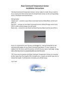
IMPORTANT: Terminals must be soldered to the
cable ends to ensure good electrical contact. Use
electrical grade (resin fl ux) solder only. Do not use
acid fl ux solder as it may cause corrosion and a
subsequent failure.
BATTERY CABLES
Cable Length Cable Gauge
Up to 3-1/2 ft. (1.1 m) 4 (19 mm
2
)
3-1/2 - 6 ft. (1.1 - 1.8 m) 2 (32 mm
2
)
6 - 7-1/2 ft. (1.8 - 2.3 m) 1 (40 mm
2
)
7-1/2 - 9-1/2 ft. (2.3 - 2.9 m) 0 (50 mm
2
)
9-1/2 - 12 ft. (2.9 - 3.7 m) 00 (62 mm
2
)
12 - 15 ft. (3.7 - 4.6 m) 000 (81 mm
2
)
15 - 19 ft. (4.6 - 5.8 m) 0000 (103 mm
2
)
INSTRUMENTATION
CAUTION
If a Crusader wiring harness is used, and a fused
accessory panel is to be installed (30 amp current
draw maximum), be sure to connect it as shown in
wiring diagram. Do not connect accessory panel at
any other location, as wires in wiring harness may not
be of suffi cient size to handle current load.
For ECM-07 equipped engines, instrumentation at
the dash is no longer driven by separate senders
on the engine. Instrumentation is now driven by the
engine control module (ECM-07) and is just another
function of the engine management system. As such,
programming or calibration of the ECM is critical for
proper instrumentation operation.
The 4 basic gauges which must be used with the engine
are:
Tachometer
Oil Pressure
Water Temperature
Voltmeter
If you experience erroneous instrumentation readings,
the most common reasons for this condition are:
(1) The boat is equipped with dual helm
instrumentation. Verify through your selling
distributor/dealer that the calibration in the ECM
is for dual helm instrumentation.
(2) Some instruments may still require instrument
specifi c senders to be installed on the engine.
Contact your selling distributor/dealer with your
instrument manufacturer’s name. You may need
to install an oil pressure and water temperature
sender on your engine and use a different engine
to boat harness adapter.
(3) Faulty wire connections at the instrument panel
and/or the old instruments are defective and need
to be replaced.
Refer to pages 20 and 25, for replacement boat
harnesses, adapter harnesses, and Sync-N-Cruz Speed
Control Harness + FWMurphy Instrument interface.
Crusader Engines are equipped with the ECM-07 engine
management system. This system outputs J1939 and
NEMA 2000 protocol messages that may be utilized by
various manufacturers of multifunction displays; such as,
FWMurphy’s CAN Bus instruments and PowerView and
HelmView, which provide expanded display capabilities.
Always check with the manufacturer of the
instrument you are considering, prior to purchase,
for compatibility. These multifunction digital displays
not only display typical engine data, such as oil pressure,
water temperature, tach, etc., but also provide expanded
displays for fuel consumption, ECM-07 diagnostic code
display, and much more.
When replacing or installing the main boat harness,
route the instrumentation wiring harness back to the
engine, making sure that the harness does not rub or get
pinched. If an extension harness is required, be sure to
secure the connection properly. Fasten harness to the
boat at least every 18 in. (45.72 cm) using appropriate
fasteners.
TWIN ENGINE SYNCHRONIZATION AND
SPEED CONTROL (OPTIONAL)
MY 2007 and newer multi-port fuel injected engines
are equipped with the ECM-07 engine management
system. This new system has allowed more features to
be available than ever before. One of signifi cance is the
ability to provide twin engine synchronization and speed
control without having to add expensive aftermarket
equipment. This feature is available on all ECM-07
multi-port fuel injected engine models. Refer to the
diagram on page 23 for the accessory harnesses and
keypad required to enable this feature.
REQUIREMENTS:
• Master/Slave Harness - RA121072C
• Sync-N-Cruz Kit - RF152007
NOTE: The Sync-N-Cruz Contorl Panel and harnesses
are available as separate items for unique installation
requirements. Refer to page 23 for harness options.
IMPORTANT: Sync-N-Cruz harness must be connected
to the Master engine.
Refer to the Crusader Owners Manual for operating
instructions for the Sync-N-Cruz system.
14
L510023-07
making sure that the wires do not rub or get pinched.
Fasten wire(s) to the boat at least every 18 in. (45.72
cm) using appropriate fasteners.
Using existing Round 10-pin BOAT
harness connector
Pin-4 = Buzzer
Pin-9 - MIL or Check Engine Lamp
Verify that connections exist at the helm. If not,
two new wires will be required between the helm
and pins 4 (MIL) and 6 (Buzzer) of the Engine
harness 8-pin Deutsch connector.
Using existing Rectangular 8-pin BOAT
harness connector
* Requires two additional wires for the MIL and
Buzzer. The MIL is connected to pin-6 and
the Buzzer is connected to pin-4 of the Engine
harness, 8-Pin, Deutsch connector.
Using the Crusader boat harness (P/N
RA121092/RA121092A), the MIL is wired at
the helm to the Green/Yellow wire and the
Buzzer is wired to the Tan/Black wire.
If previously equipped with the Optional
Crusader Warning Light Cluster P/N 23505:
Figure 17 Optional Warning Light Cluster - Crusader
Part No. 23505
When installing the Sync-N-Cruz harness, route the
harness back to the Master engine, making sure that the
harness does not rub or get pinched. If an extension
harness is required, be sure to secure the connection
properly. Fasten harness to the boat at least every 18
in. (45.72 cm) using appropriate fasteners.
MASTER/SLAVE WIRING CONNECTION
This connection allows the CAN Bus data lines to be
joined together for dual engine applications.
The benefi ts of a Master/Slave connection are:
Allows for twin engine Sync-N-Cruz operation.
Electronic Engine Monitor systems installed at
the helm area may display engine data for both
engines.
IMPORTANT: In dual engine applications, the
master/slave wiring harness is used to connect the
engines together. One end of this harness has one
more wire in it than the other end. The end with the
extra wire is plugged into the Slave engine harness.
This extra wire is then attached to the ground stud
on the Slave engine.
ENGINE WARNING KIT (OPTIONAL)
An engine warning kit, RK179008, is available. This kit
contains a Check Engine Lamp and Warning Buzzer.
It is recommended that the boat be equipped with a
Check Engine Lamp (Malfunction Indicator Lamp - MIL)
and buzzer. These devices warn the boat operator of
potential engine problems.
WATER
TEMP
OIL
PRESS
CHK
ENGINE
TRANS
TEMP
Figure 16 Optional Warning Light / Alarm - Crusader
Part No. RK179008
Some boat wiring may already support these devices
and/or they may already be installed at the helm.
Ensure that the new connections match up to the
existing boat wiring and warning devices.
Ensure the light and buzzer wires are in the existing boat
harness, otherwise new wires will have to be run from
the helm to the engine. Use 18 ga minimum wire size,
The Check Engine lamp, of the cluster, and
the existing Buzzer may be used with ECM-07
engine models.
(1) At each engine, locate the Warning Cluster
Harness, 8-pin connector. The wires at Pin-A
(Orange/Tan wire, Check Engine Lamp) and
Pin-B (Tan/Red wire, Buzzer) will be the only
wires used. Cut the 8-Pin connector off of the
harness and tape back the wires not used.
15
L510023-07
(2) Splice pin-A (Orange/Tan) to pin-6 of the
respective engine 8-pin Deutsch connector and
pin-B (Tan/Red) to pin-4 of the engine 8-pin
connector. Only, the Check Engine Lamp
and alarm buzzer of the warning cluster will be
functional. Refer to the wiring diagram below
for connection/splice options for the MIL and
Buzzer.
Engine Side
Dash Side
Part Number -
RA121093
WATER
TEMP
OIL
PRESS
CHK
ENGINE
TRANS
TEMP
WATER
TEMP
OIL
PRESS
CHK
ENGINE
TRANS
TEMP
ENGINE
HARNESS
ENGINE
HARNESS
Part Number -
RA121093
Master / Slave
Engine Harness
Part Number -
RA121072C
PORT/
SLAVE
ENGINE
GND
STARBOARD/
MASTER
ENGINE
Existing Boat
Harness
Existing Boat
Harness
PIN-B TAN/RED
SPLICE TO
TAN/BLACK IN
RA121093
PIN-A ORANGE/TAN
SPLICE TO
GREEN/YELLOW
IN RA121093
CUT 8-PIN
CONNECTOR
OFF HARNESS
CUT 8-PIN
CONNECTOR
OFF HARNESS
PIN-B TAN/RED
SPLICE TO
TAN/BLACK IN
RA121093
PIN-A ORANGE/TAN
SPLICE TO
GREEN/YELLOW
IN RA121093
98387/98388
HARNESS
98387/98388
HARNESS
23505
Display
23505
Display
Existing Harness and
Warning Cluster
Existing Harness and
Warning Cluster
16
L510023-07
ELECTRICAL SYSTEM PRECAUTIONS
To avoid damage to the electronic fuel injection (EFI)
system, the following precautions must be observed
when adding additional electric accessories.
DO NOT reverse battery leads.
DO NOT splice wires into engine electrical harness.
DO NOT puncture engine wires for testing
(probing).
DO NOT attempt engine diagnostics without the
proper service tools.
DO NOT attach any accessory wiring to the ECM
ground location.
Figure 19 Master / Slave Wire Harness
Figure 18 ECM Slave Ground Terminal
Figure 20 Electrical System Connectors
SLAVE ENGINE
GROUND TERMINAL
TO SLAVE ENGINE
GROUND STUD
TO SLAVE
ENGINE
TO MASTER
ENGINE
SPEED CONTROL/
CAN BUS
CONNECTOR
FUEL TANK
SOLENOID
CONNECTOR
TWIN ENGINE
MASTER/SLAVE
CONNECTOR
2-PIN BOAT
HARNESS
CONNECTOR
8-PIN BOAT
HARNESS
CONNECTOR
INSTALLATION NOTE: When installing the
Optional Crusader Sync-N-Cruz system, the speed
control harness (RA121091/RA121091A) MUST be
connected to the Master engine, 20-Pin Speed Control/
CAN Bus Connector and the master/slave harness
(RA121072C) must connect the Master and Slave
engines together. Ensure that the Slave side of the
harness is grounded to the Slave engine.
  • Page 1 1
  • Page 2 2
  • Page 3 3
  • Page 4 4
  • Page 5 5
  • Page 6 6
  • Page 7 7
  • Page 8 8
  • Page 9 9
  • Page 10 10
  • Page 11 11
  • Page 12 12
  • Page 13 13
  • Page 14 14
  • Page 15 15
  • Page 16 16
  • Page 17 17
  • Page 18 18
  • Page 19 19
  • Page 20 20
  • Page 21 21
  • Page 22 22
  • Page 23 23
  • Page 24 24
  • Page 25 25
  • Page 26 26
  • Page 27 27
  • Page 28 28
  • Page 29 29
  • Page 30 30
  • Page 31 31
  • Page 32 32
  • Page 33 33
  • Page 34 34
  • Page 35 35
  • Page 36 36
  • Page 37 37
  • Page 38 38
  • Page 39 39
  • Page 40 40
  • Page 41 41
  • Page 42 42
  • Page 43 43
  • Page 44 44
  • Page 45 45
  • Page 46 46
  • Page 47 47
  • Page 48 48
  • Page 49 49
  • Page 50 50
  • Page 51 51
  • Page 52 52
  • Page 53 53
  • Page 54 54
  • Page 55 55
  • Page 56 56
  • Page 57 57
  • Page 58 58
  • Page 59 59
  • Page 60 60
  • Page 61 61
  • Page 62 62
  • Page 63 63
  • Page 64 64
  • Page 65 65
  • Page 66 66
  • Page 67 67
  • Page 68 68
  • Page 69 69
  • Page 70 70
  • Page 71 71
  • Page 72 72
  • Page 73 73
  • Page 74 74
  • Page 75 75
  • Page 76 76
  • Page 77 77
  • Page 78 78
  • Page 79 79
  • Page 80 80
  • Page 81 81
  • Page 82 82
  • Page 83 83
  • Page 84 84
  • Page 85 85
  • Page 86 86
  • Page 87 87
  • Page 88 88
  • Page 89 89
  • Page 90 90
  • Page 91 91
  • Page 92 92
  • Page 93 93
  • Page 94 94
  • Page 95 95
  • Page 96 96
  • Page 97 97
  • Page 98 98
  • Page 99 99
  • Page 100 100
  • Page 101 101
  • Page 102 102
  • Page 103 103
  • Page 104 104
  • Page 105 105
  • Page 106 106
  • Page 107 107
  • Page 108 108
  • Page 109 109
  • Page 110 110
  • Page 111 111
  • Page 112 112
  • Page 113 113
  • Page 114 114
  • Page 115 115
  • Page 116 116
  • Page 117 117
  • Page 118 118
  • Page 119 119
  • Page 120 120
  • Page 121 121
  • Page 122 122
  • Page 123 123
  • Page 124 124
  • Page 125 125
  • Page 126 126
  • Page 127 127
  • Page 128 128
  • Page 129 129
  • Page 130 130
  • Page 131 131
  • Page 132 132
  • Page 133 133
  • Page 134 134
  • Page 135 135
  • Page 136 136
  • Page 137 137
  • Page 138 138
  • Page 139 139
  • Page 140 140
  • Page 141 141
  • Page 142 142
  • Page 143 143
  • Page 144 144
  • Page 145 145
  • Page 146 146
  • Page 147 147
  • Page 148 148
  • Page 149 149
  • Page 150 150
  • Page 151 151
  • Page 152 152
  • Page 153 153
  • Page 154 154
  • Page 155 155
  • Page 156 156
  • Page 157 157

Crusader MP 6.0L Product Installation Manual

Category
Engine
Type
Product Installation Manual
This manual is also suitable for

Ask a question and I''ll find the answer in the document

Finding information in a document is now easier with AI