La Nordica Ellipse Owner's manual
- Category
- Stoves
- Type
- Owner's manual

ELLIPSE
Testata secondo / Tested according to / Geprüft nach / Certifié selon : EN 13240
|
NORME DI SICURE
ZZA SUGLI APPARECCHI
Secondo le norme di sicurezza sugli apparecchi l’acquirente e l’esercente sono obbligati ad informarsi sul
corretto funzionamento in base alle istruzioni per l’uso.
SAFETY REGULATIONS ON THE DEVICES
According to the safety prescriptions on equipment, the purchaser and the operator and obliged to get
informed about the correct operation according to the instructions for use.
SICHERHEITSBESTIMMUNGEN FÜR DIE GERÄTE
Nach den Sicherheitsbestimmungen für die Geräte sind der Käufer und der Betreiber verpflichtet, sich auf
der Grundlage der Bedienungsanleitung über den richtigen Betrieb zu informieren.
NORMES DE SECURITE DES APPAREILS
Conformément aux normes de sécurité sur les appareils, l'acheteur et l'utilisateur sont obligés de s'informer
sur le fonctionnement correct sur la base des instructions d'utilisation.
!
ISTRUZIONI PER L’INSTALLAZIONE, L’USO E LA MANUTENZIONE -IT
INSTRUCTIONS FOR INSTALLATION, USE AND MAINTENANCE - EN
ANWEISUNGEN FÜR DIE AUFSTELLUNG, DEN GEBRAUCH UND DIE WARTUNG – DE
INSTRUCTIONS POUR L’INSTALLATION, L’UTILISATION ET L’ENTRETIEN - FR
IT
–
PER EVITARE DANNI ALL’APPARECCHIO, RISPETTARE IL CARICO ORARIO DI COMBUSTIBILE INDICATO NEL
PRESENTE LIBRETTO.
EN –
TO AVOID DAMAGES TO THE APPLIANCE, PLEASE RESPECT THE MAX. FUEL QUANTITY (KG/HR) INDICATED IN
THE USER’S MANUAL.
DE – UM SCH
ÄDEN AN DEM GERÄT ZU VERMEIDEN, BITTE BEACHTEN SIE DIE BRENNSTOFFMENGE (KG/H) LT.
BEDIENUNGSANLEITUNG.
FR –
POUR EVITER DES DOMMAGES A L’APPAREIL RESPECTER LA QUANTITE’ MAX. DE COMBUSTIBLE (KG/H)
COMME INDIQUE DANS LA NOTICE D’UTILISATION.
Page is loading ...

ELLIPSE
7196901 Rev.09 – IT – EN – DE – FR 3
DICHIARAZIONE DI CONFORMITA’ DEL COSTRUTTORE
Oggetto: assenza di amianto e cadmio
Si dichiara che tutti i nostri apparecchi vengono assemblati con materiali che non presentano parti di
amianto o suoi derivati e che nel materiale d’apporto utilizzato per le saldature non è presente/utilizzato in
nessuna forma il cadmio, come previsto dalla norma di riferimento.
Oggetto: regolamento CE n. 1935/2004
Si dichiara che in tutti gli apparecchi da noi prodotti, i materiali destinati a venire a contatto con i cibi sono
adatti all’uso alimentari, in conformità al Regolamento CE in oggetto.
DECLARATION OF CONFORMITY OF THE MANUFACTURER
Object: Absence of asbestos and cadmium
We declare that the materials used for the assembly of all our appliances are without asbestos parts or
asbestos derivates and that in the material used for welding, cadmium is not present, as prescribed in
relevant norm.
Object: CE n. 1935/2004 regulation.
We declare that in all products we produce, the materials which will get in touch with food are suitable for
alimentary use, according to the a.m. CE regulation.
KONFORMITÄTSERKLÄRUNG DES HERSTELLERS
Betreff: Fehlen von Asbest und Kadmium
Wir bestätigen, dass die verwendeten Materialen oder Teilen für die Herstellung der La Nordica Geräte
ohne Asbest und Derivat sind und auch das Lot für das Schweißen immer ohne Kadmium ist.
Betreff: Ordnung CE n. 1935/2004. Wir erklären in alleiniger Verantwortung, dass die Materialien der
Teile, die für den Kontakt mit Lebensmitteln vorgesehen sind, für die Nahrungsbenutzung geeignet sind
und der Richtlinien CE n. 1935/2004 erfüllen
DÉCLARATION DE CONFORMITÉ DU FABRICANT
Objet: absence d'amiante et de cadmium
Nous déclarons que tous nos produits sont assemblés avec des matériaux qui ne présentent pas de
parties en amiante ou ses dérivés et que le matériel d'apport utilisé pour les soudures ne présente/utilise
pas de cadmium, sous aucune forme, comme prévu par la norme de référence.
Objet: Règlement CE n. 1935/2004. Nous déclarons que dans tous nos appareils, les matériaux destinés
à entrer en contact avec les aliments sont aptes à l'usage alimentaire, conformément au Règlement CE
en question.

ELLIPSE
4 7196901 Rev.09 – IT – EN – DE – FR
INDICE IT
1. DATI TECNICI .......................................................................................................................................................... 6
2. DESCRIZIONE TECNICA......................................................................................................................................... 6
3. NORME PER L’INSTALLAZIONE ............................................................................................................................ 7
4. SICUREZZA ANTINCENDIO .................................................................................................................................... 8
4.1. PRONTO INTERVENTO ................................................................................................................................................... 9
5. CANNA FUMARIA .................................................................................................................................................... 9
6. COLLEGAMENTO AL CAMINO ............................................................................................................................. 10
6.1. POSIZIONE DEL COMIGNOLO ...................................................................................................................................... 10
7. COMBUSTIBILI AMMESSI / NON AMMESSI ........................................................................................................ 12
8. AFFLUSSO DELL’ARIA NEL LUOGO D’INSTALLAZIONE DURANTE LA COMBUSTIONE ............................... 12
9. ACCENSIONE ........................................................................................................................................................ 13
10. FUNZIONAMENTO NORMALE .......................................................................................................................... 14
11. FUNZIONAMENTO NEI PERIODI DI TRANSIZIONE ........................................................................................ 14
12. MANUTENZIONE E CURA................................................................................................................................. 14
12.1. PULIZIA CANNA FUMARIA ............................................................................................................................................ 15
12.2. PULIZIA VETRO .............................................................................................................................................................. 15
12.3. PULIZIA CASSETTO CENERE ....................................................................................................................................... 15
12.4. LE MAIOLICHE ............................................................................................................................................................... 15
13. FERMO ESTIVO ................................................................................................................................................. 15
14. COLLEGAMENTO ALLA CANNA FUMARIA DI UN CAMINETTO O FOCOLARE APERTO ........................... 16
15. MONTAGGIO DELLE CERAMICHE / THE ASSEMBLY OF CERAMICS / KACHELNBAUANLEITUNGEN /
M
ONTAGE DES CÉRAMIQUES .................................................................................................................................... 50
16. SCHEDA TECNICA / TECHNICAL DATA SHEETS / TECHNISCHE PROTOKOLLE / FICHE TECHNIQUE .. 55
INDEX EN
1. TECHNICAL DATA ................................................................................................................................................. 17
2. TECHNICAL DESCRIPTION .................................................................................................................................. 17
3. RULES FOR INSTALLATION ................................................................................................................................. 18
3.1. CLEAN AIR ACT RESTRICTOR KIT – DEFRA – (ONLY FOR UK SMOKE CONTROL AREAS) ................................... 19
4. FIRE SAFETY MEASURES ................................................................................................................................... 19
4.1. FIRST-AID MEASURES .................................................................................................................................................. 20
5. FLUE ....................................................................................................................................................................... 20
6. CONNECTION TO THE CHIMNEY ........................................................................................................................ 21
6.1. CHIMNEY CAP POSITION .............................................................................................................................................. 21
7. ADMITTED/NOT ADMITTED FUEL ....................................................................................................................... 22
8. AIR ENTRANCE INTO THE INSTALLATION PLACE DURING THE COMBUSTION .......................................... 23
9. LIGHTING ............................................................................................................................................................... 24
10. NORMAL OPERATION ...................................................................................................................................... 24
11. OPERATION DURING TRANSITION PERIODS ............................................................................................... 25
12. MAINTENANCE AND CARE .............................................................................................................................. 25
12.1. CLEANING OF THE FLUE .............................................................................................................................................. 25
12.2. CLEANING OF THE GLASS ........................................................................................................................................... 26
12.3. CLEANING OF THE ASH DRAWER ............................................................................................................................... 26
12.4. MAJOLICAS .................................................................................................................................................................... 26
13. SUMMER STOP ................................................................................................................................................. 26
14. CONNECTING A CHIMNEY OR OPEN FURNACE TO THE FLUE .................................................................. 27
15. MONTAGGIO DELLE CERAMICHE / THE ASSEMBLY OF CERAMICS / KACHELNBAUANLEITUNGEN /
M
ONTAGE DES CÉRAMIQUES .................................................................................................................................... 50
16. SCHEDA TECNICA / TECHNICAL DATA SHEETS / TECHNISCHE PROTOKOLLE / FICHE TECHNIQUE .. 55

ELLIPSE
7196901 Rev.09 – IT – EN – DE – FR 5
INHALTSVERZEICHNIS DE
1. TECHNISCHE DATEN ........................................................................................................................................... 28
2. TECHNISCHE BESCHREIBUNG ........................................................................................................................... 28
3. AUFSTELLHINWEISE ............................................................................................................................................ 29
4. BRANDSCHUTZ ..................................................................................................................................................... 30
4.1. NOTFALLMASSNAHMEN ............................................................................................................................................... 31
5. SCHORNSTEINROHR ........................................................................................................................................... 31
6. KAMINANSCHLUSS ............................................................................................................................................... 32
6.1. SCHORNSTEIN .............................................................................................................................................................. 32
7. ZULÄSSIGE/UNZULÄSSIGE BRENNSTOFFE ..................................................................................................... 34
8. LUFTZUFLUSS AM AUFSTELLORT WÄHREND DER VERBRENNUNG ............................................................ 34
9. ANFEUERUNG ....................................................................................................................................................... 35
10. NORMALBETRIEB ............................................................................................................................................. 36
11. BETRIEB IN DER ÜBERGANGSZEIT ............................................................................................................... 36
12. WARTUNG UND PFLEGE ................................................................................................................................. 36
12.1. REINIGUNG DES SCHORNSTEINS .............................................................................................................................. 37
12.2. REINIGUNG DES GLASES ............................................................................................................................................. 37
12.3. REINIGUNG DES ASCHKASTENS ................................................................................................................................ 37
12.4. DIE MAJOLIKEN ............................................................................................................................................................. 37
13. SOMMERPAUSE ................................................................................................................................................ 38
14. ANSCHLUSS AN DEN RAUCHABZUG EINES OFFENEN KAMINS ................................................................ 38
15. MONTAGGIO DELLE CERAMICHE / THE ASSEMBLY OF CERAMICS / KACHELNBAUANLEITUNGEN /
M
ONTAGE DES CÉRAMIQUES .................................................................................................................................... 50
16. SCHEDA TECNICA / TECHNICAL DATA SHEETS / TECHNISCHE PROTOKOLLE / FICHE TECHNIQUE .. 55
TABLE DES MATIERES FR
1. DONNÉES TECHNIQUES ..................................................................................................................................... 39
2. DESCRIPTION TECHNIQUE ................................................................................................................................. 39
3. NORMES POUR L’INSTALLATION ....................................................................................................................... 40
4. SECURITE ANTI-INCENDIE .................................................................................................................................. 41
4.1. INTERVENTIONS D'URGENCE ..................................................................................................................................... 42
5. CONDUIT DE CHEMINEE ..................................................................................................................................... 42
6. RACCORDEMENT A LA CHEMINEE .................................................................................................................... 43
6.1. POSITION DU TERMINAL DE CHEMINEE .................................................................................................................... 43
7. COMBUSTIBLES ADMIS / NON ADMIS ................................................................................................................ 45
8. AFFLUX DE L'AIR DANS LE LIEU D'INSTALLATION PENDANT LA COMBUSTION.......................................... 45
9. ALLUMAGE ............................................................................................................................................................ 46
10. FONCTIONNEMENT NORMAL.......................................................................................................................... 47
11. FONCTIONNEMENT AU COURS DES PÉRIODES DE TRANSITION ............................................................. 47
12. MAINTENANCE ET SOIN .................................................................................................................................. 47
12.1. NETTOYAGE DU TUYAU D'ÉVACUATION DES FUMÉES ........................................................................................... 48
12.2. NETTOYAGE DE LA VITRE ............................................................................................................................................ 48
12.3. NETTOYAGE DU TIROIR DES CENDRES .................................................................................................................... 48
12.4. LES FAÏENCES ............................................................................................................................................................... 48
13. REPOS ESTIVAL ................................................................................................................................................ 49
14. RACCORDEMENT AU TUYAU D'ÉVACUATION DES FUMÉES D'UNE CHEMINÉE OU UN FOYER
O
UVERT ......................................................................................................................................................................... 49
15. MONTAGGIO DELLE CERAMICHE / THE ASSEMBLY OF CERAMICS / KACHELNBAUANLEITUNGEN /
MONTAGE DES CÉRAMIQUES .................................................................................................................................... 50
16. SCHEDA TECNICA / TECHNICAL DATA SHEETS / TECHNISCHE PROTOKOLLE / FICHE TECHNIQUE .. 55
Page is loading ...
Page is loading ...
Page is loading ...
Page is loading ...
Page is loading ...
Page is loading ...
Page is loading ...
Page is loading ...
Page is loading ...
Page is loading ...
Page is loading ...

ELLIPSE
7196901 Rev.09 – EN 17
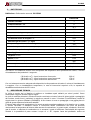
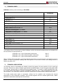
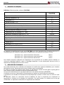
1. TECHNICAL DATA
Definition: chimney stove according to EN 13240
ELLIPSE
Constructive system
1
Rating power in kW
8
Efficiency in %
78.1
Pipe diameter in mm
160
Hourly wood consumption in kg / h (wood with 20% humidity)
2.4
Depression by rating calorific value in mm H
2
O wood
1.2
Mean content of CO to 13% O
2
in %
0.09
Emission of exhaust gases in g/s- wood
7.3
Temperature of exhaust gases in °C - wood
312
Size of hearth opening mm (W x H)
540x245
Hearth body size /Hearth head in mm (W x H x D)
500x320x360
Grate type
Flat grate
Stove width in mm
1240
Stove height in mm
1135
Stove depth (without handles) in mm
680
Weight in kg
251
Safety measures
Chapter 4
The heating volume of the stoves for those buildings in which the thermal insulation does not correspond to
the instructions on heat protection is:
(30 Kcal/h x m
3
) - type of favourable construction 230 m³
(
40 Kcal/h x m
3
) - type of less favorable construction 170 m³
(50 Kcal/h x m
3
) - type of unfavorable construction 138 m³
With a suitable thermal insulation, complying with the instructions on heat protection, the heating volume is
greater. In case of temporary heating, with interruptions of more than 8 hours, the heating volume is
reduced by about 25%.
2. TECHNICAL DESCRIPTION
The chimney stoves of La Nordica are suitable to heat living spaces for some periods. As fuel, wood logs
are used. The stove is made of sheets in galvanized and painted steel, of cast iron (grate and grate holder
of the hearth, exhaust pipe) of majolica tiles and of glass panels. The hearth is totally sheathed with cast-
iron single sheets and refractory material (IRONKER). Inside there are a easy extractable thick flat grate
and its holder. The combustion chamber is hermetic welded and is sheathed with a painted steel carter.
The inside smoke plate made of vermiculite, reflects the fire radiation and increases the internal
temperature of the combustion chamber. This process together with the exhaust gases flows, makes
optimal the combustion and improves the efficiency.

ELLIPSE
18 7196901 Rev.09 – EN
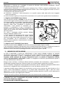
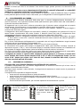
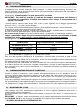
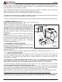
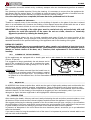
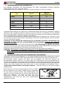
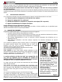
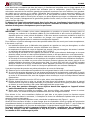
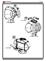
Singular feature of the model “Carillon” is the pivoting body, i.e. the possibility of rotating the stove of +-
45° (with regard to its base axis) also when is lighted. It is also possible to block the appliance at the
wished position by a knob. (Picture 1 pos.A)
The one-piece ceramic glass of the door (resistant up to 700 °C) allows a wonderful view on the burning
flames. Furthermore, it is thus avoided the output of sparks and smoke.
Below the hearth grate there is an extractable ash drawer, (Picture 9 pos. A).
The heating of the environment is made by irradiation: through the panoramic glass and the external hot
surfaces of the stove, the heat is radiated into the environment.
The stove is equipped with controls of primary and secondary air by which it is adjusted the combustion air.
1 - PRIMARY air register (left lever)
Below the hearth door, on the front left side, there is the primary air
register, in the style of lever (Picture 1 - 1)
With this air register, it is adjusted the passage of primary
air into the low part of the stove and through particular
channels flows in the fuel direction. The primary air is
necessary for the combustion process during lighting. The
ash drawer must be regularly emptied, so that the ash
does not obstruct the entry of the primary air for the
combustion.
In order to open the air flow, the bar must be completely
pulled out,
During wood combustion, the register of primary air must
be opened only for a while, because otherwise the wood
burns too fast and the stove may overheat. For the coal
combustion, the arrival of primary air is absolutely
necessary (see paragraph 10).
2 - SECONDARY air register (right lever)
Below the hearth door, on the right front side there is the
secondary air register (Picture 1 - 2).
The secondary air, passing through the two lateral jambs
of the front side, heats itself starting the double combustion and keeping at the same time the glass clean
(with open register).
When the bar is pushed to the back the passage of the secondary is completely open (Picture 1 - 2).
3. RULES FOR INSTALLATION
The stove, assembled and ready for the installation, must be connected with a junction to the existing flue
of the house. The junction must be possibly short, straight, horizontal or positioned a little uphill. The
connections must be tight.
It is obligatory to respect the National and European rules, local regulations concerning building
matter and also fireproof rules. Please apply to your chimney sweeper for all information.
You should verify the sufficient air entrance for the combustion in the installation place, with particular
attention to windows and doors with tight closing (seal ropes).
It is not allowed the connection of various appliances to the same chimney. The diameter of the opening for
the connection must correspond at least to the diameter of the smokes pipe. The opening should be
equipped with a wall connection for the reception of the exhaust pipe and a rose window.
Before installation, verify if your floor can support the weight of the stove (for ex. distributing weight plate).
Please do not install the stove in a inclined level in order to avoid tensions during the rotation.
LA NORDICA is not responsible in case of modification of the product and for the use of not
original spare parts. The hearths must not be modified. THE HEARTHS MUST NOT BE MODIFIED.
Picture 1
A
2
1
A

ELLIPSE
7196901 Rev.09 – EN 19
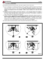
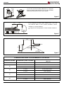
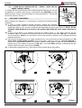
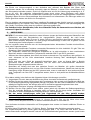
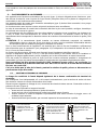
3.1. CLEAN AIR ACT RESTRICTOR KIT – DEFRA – (ONLY FOR UK
SMOKE CONTROL AREAS)
To comply with the requirements of the United Kingdom Clean Air Act, for use
of appliances in smoke control areas, a permanent stop (SF07224) must be
fitted to prevent closure of the secondary air control beyond 40%. This should
be fitted as shown in Picture 2.
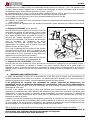
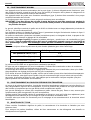
4. FIRE SAFETY MEASURES
While installing the appliance, it is necessary to respect the following safety
measures:
a) In order to ensure sufficient thermal insulation, respect the minimum
safety distance from objects or furnishing components flammable and sensitive to heat (furniture, wood
sheathings, fabrics. etc.) and from materials with flammable structure (see Picture 3 A1-A2). All the
minimum safety distances are shown on the product data plate and lower values must not be
used.
b) In front of the hearth, in its radiation area and its rotation space (+- 45°) there must not be any
flammable object or construction material sensitive to the heat at least within 100 cm; This distance
can be reduced to 40 cm if you will install in front of the element to protect a retro ventilated and heat
resistant protection.
c) If the product is installed on a non totally refractory floor, one must foresee a fireproof background. The
floors made of inflammable material, such as moquette, parquet or cork etc., must be replaced by
a layer of no-inflammable material, for instance ceramic, stone, glass or steel etc. (size according to
r
egional filing). The platform must stick out 50 cm in front and 20cm sideways, considering also the
rotation field of the stove. (see Picture 3 B1-B2).
d) no flammable components (e.g. wall units) must be present above the product.
Picture 2
Picture 3
10
100
10
10
20
50
20
100
10
10
47
50
20
20
47

ELLIPSE
20 7196901 Rev.09 – EN
The stove must work exclusively with inserted ash drawer.
Solid combustion residuals (ashes) must be collected in an air-tight and fire-resistant container. The
appliance must never be switched on when there are gaseous emissions or vapours (for example glue for
linoleum, gasoline etc.). Do not deposit flammable materials close to the same.
During the combustion will be spread thermal energy which warms up the surfaces, the door, the fireplace
glass, the handles and knobs, the smoke pipe and the front side of the stove. Please avoid the contact of
these parts without gloves or the relevant tools.
Warn children of the danger and keep them away during the operation of the stove.
The use of a wrong or wet fuel causes the formation of creosote deposits in the flue and will fuel a chimney
fire.
4.1. FIRST-AID MEASURES
Should any fire arise in the stack or in the flue:
a) Close the feeding door and the ash drawer door.
b) Close the registers of combustion air
c) Extinguish the fire using carbon dioxide fire-fighting means (CO2 dust).
d) Seek immediate intervention of FIRE BRIGADE.
D
O NOT EXTINGUISH FIRE USING WATER JETS
When the fire has been extinguished, let the flue check by an expert to find possible cracks and permeable
points.
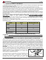
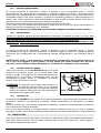
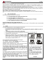
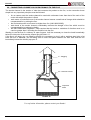
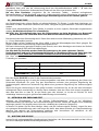
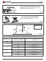
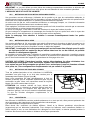
5. FLUE
Essential requirements for a correct operation of the device:
• the internal section must be preferably circular;
• be thermally insulated and water-proof and produced with materials suitable to resist to
heat,
• combustion products and possible condensates;
• not be throttled and show a vertical arrangement with deviations not greater than 45°;
• if already used, it must be clean;
• observe the technical data of the instructions manual;
Should the flues have a square or rectangular section,
internal edges must be rounded with a radius not lower
than 20 mm. For the rectangular section, the maximum
ratio between the sides must be ≤ 1.5.
A too small section causes a decrease of the draught.
It is suggested a minimum height of 4 m.
The following features are forbidden and therefore they
endanger the good operation of the device:
asbestos cement, galvanized steel, rough and porous internal
surfaces. Picture 4 gives some examples of execution.
T
he minimum section must be 4 dm2 (for example 20 x 20
cm) for devices whose duct diameter is lower than 200 mm
or 6.25 dm2 (for example 25 x 25 cm) for devices with
d
iameter greater than 200 mm.
The draught created by the flue must be sufficient, but not
excessive.
A too big flue section can feature a too big volume to be heated
and consequently cause difficulties in the operation of the device;
to avoid this, tube the flue along its whole height. A too small
section causes a decrease of the draught.
The flue must be properly spaced from any flammable
materials or fuels through a proper insulation or an air
cavity.
Picture 4
(1) AISI 316 steel flue with double
chamber insulated with material resistant
to 400°C. Efficiency 100% excellent.
(2) Refractory flue with double insulated
c
hamber and external coating in
lightweight concrete. Efficiency 100%
excellent.
(3) Traditional clay flue square section
with cavities. Efficiency 80% excellent.
(4) Avoid flues with rectangular internal
section whose ratio differs from the
drawing. Efficiency 40% poor.
A+1/2A
A
Max.
A+1/2A
(3)
(1)
(2)
(4)

ELLIPSE
7196901 Rev.09 – EN 21
It is forbidden to let plant piping or air feeding channels pass in the same flue. Moreover, it is forbidden to
create movable or fixed openings on the same for the connection of further other devices.
6. CONNECTION TO THE CHIMNEY
For safety reasons the door of the appliances with constructive system 1, must be opened only for the
loading of the fuel or for removing the ashes, while during the operation and the rest, the door of the hearth
must remain closed.
The appliances with constructive system 2 must be connected to their own flue. The operating with open
door is allowed under supervision. The connection pipe to the flue must be the shortest possible, right, tight
and according to the current regulations.
The connection to the chimney must be performed with stable and strong pipes (we recommend a
thickness of 2 mm). The pipe for smokes exhaust must be fixed hermetically to the chimney. The diameter
inside the connection pipe must correspond to the external diameter of the smokes exhaust small trunk of
the stove. This is ensured by pipes according to DIN 1298.
ATTENTION: Eventual flammable pieces in the area of 20 cm round the connection pipes must be
changed with fireproof and not sensitive to heat materials.
For a good operation of the equipment it is essential that in the installation place it is introduced sufficient
air for combustion (see CHAPT. 10).
The depression on the chimney should be 12 Pa (=1.2 mm of water column). The measurement must be
done always with the equipment hot (rating calorific value). When the depression exceeds 17 PA (1.7mm
of water column) it is necessary to reduce the same with the installation of an additional flue adjuster
(butterfly valve) on the exhaust pipe or in the chimney.
For safety reasons the door of the stove must be opened only for the loading of the fuel or for removing the
ashes, while during the operation and the rest, the door of the hearth must remain closed.
During its operation we suggest you slowly rotate the stove ELLIPSE. The rosette of the flue must
be fixed with nails or screws and the junction pipe must be fixed with a 90°bend, in order to avoid
during the rotation of the stove the detachment of the smoke pipe and a consequent danger of fire.
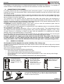
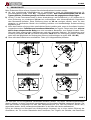
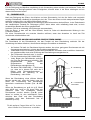
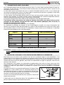
6.1. CHIMNEY CAP POSITION
The draught of the flue depends also on the suitability of the chimney cap.
Therefore, if it is handicraft constructed, the output section must be more than twice as big as the internal
section of the flue.
Should it be necessary to exceed the ridge of the roof, the chimney cap must assure the discharge also in
case of windy weather (Picture 5).
The chimney cap must meet the following requirements:
• have internal section equivalent to that of the stack.
• have a useful output section twice as big as the flue internal one.
• be manufactured in such a way as to prevent the penetration of rain, snow, and any other foreign
body in the flue.
• be easily checkable, for any possible maintenance and cleaning operation.
Picture 5
Picture 6
(1) Industrial chimney
cap with pre-fabricated
elements – it allows an
excellent discharge of the
smokes.
(2) Handicraft chimney
cap. The right output
section must be at least
twice as big as the
internal section of the flue
(ideal value: 2.5 times).
(3) Chimney cap for steel
flue with internal cone
deflector of smokes.
50 cm
(1) In case of flues side by side, a chimney cap must be higher than
the other one of at least 50 cm in order to avoid pressure transfers
between the flues themselves.

ELLIPSE
22 7196901 Rev.09 – EN
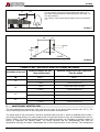
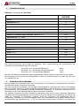
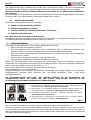
7. ADMITTED/NOT ADMITTED FUEL
The fuels admitted are wood logs. One must use only logs of dry wood (water content max. 20 %). The
size of wood logs should be 30 cm’s long and 30 cm’s max in circumference.
The wood used as fuel must have a moisture contents lower than 20 %, which is obtained after at least 1
year drying (tender wood) or 2 years (hard wood) and must be stored in a dry and ventilated place (for ex.
Under a shed). The wet wood makes ignition more difficult because it is necessary a greater quantity of
energy to evaporate the existing water. The humid contents has the disadvantage that, with the
temperature lowering, the water condensates first in the hearth and then in the chimney. The unseasoned
Picture 7
Picture 8
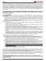
CHIMNEY CAPS - DISTANCES AND POSITIONING UNI 10683/98
Inclination of the roof
Distance between the roof
ridge and the stack
Minimum height of the stack (measured
from the outlet)
α
αα
α
A (m) H (m)
15°
< 1,85 m 0,50 m above the roof ridge
> 1,85 m 1,00 m from the roof
30°
< 1,50 m 0,50 m above the roof ridge
> 1,50 m 1,30 m from the roof
45°
< 1,30 m 0,50 m above the roof ridge
> 1,30 m 2,00 m from the roof
60°
< 1,20 m 0,50 m above the roof ridge
> 1,20 m 2,60 m from the roof
(1) The chimney cap must not show hindrances within 10 m
from walls, pitches and trees. Otherwise raise it of at least 1 m
over the hindrance.
The chimney cap must exceed the ridge of the roof of at least
1 m.
2 m
10 m
1
m
>
_
A
>A
0,5 m
H min.
α
(2)roof
(1)ridge axis

ELLIPSE
7196901 Rev.09 – EN 23
wood contains about 60 % of H20, then it is not suitable to be burnt. The following cannot be burnt:
rests of coal, cutoffs, parts of barks and panels, wet wood or treated with varnished, plastic
materials. In this case the guarantee on the appliance lapses. Paper and carton must be used only
for ignition.
The combustion of wastes is forbidden by national law on the protection against emissions. This may
damage the stove and the chimney, causing health damages and claims by the neighbourhood owing to
the bad smell.
The wood is not a fuel which allows a continuous operation of the appliance, as consequence the heating
all over the night is not possible.
variety Kg/mc
KWh/Kg
moistness 20%
Beech 750 4,0
Oak 900 4,2
Elm 640 4,1
Poplar 470 4,1
Larch* 660 4,4
Spruce* 450 4,5
Scots pine *
550 4,4
*Resinous wood not suitable for the burning
ATTENTION: the continuous and protracted use of aromatic wood (eucalyptus, myrtle etc.) quickly
damages the cast iron parts (cleavage) of the product.
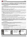
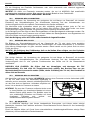
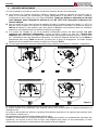
8. AIR ENTRANCE INTO THE INSTALLATION PLACE DURING THE COMBUSTION
As the stoves take their combustion air from the installation place, it is essential that a sufficient quantity of
air is introduced in the installation room itself.
In case of tight doors and windows (for example houses built according to the energy saving criteria) it is
possible that the air entrance is not guaranteed, compromising the draught, the welfare and the security of
the people. It is necessary to guarantee a further air entrance through a external air intake, to be positioned
in the nearby of the appliance or through air connection towards outside or a near ventilated room, with
the exception of thermal units place or garages (FORBIDDEN).
The stove, on the back of its pedestal, is endowed with a junction
(d. 120 mm Picture 9 pos. A) which is to be connected with a
flexible pipe for the external air intake. The connection pipe must
be flat with a minimum diameter of 120 mm, a maximum length of
4 m and with no more than 3 bends. If there is a direct connection
with the outside it must be endowed with a special windbreak.
The air entrance for combustion into the installation place must not be closed during the operation of the
stove. It is absolutely necessary that in the environment in which the stoves operate with the natural flue of
the chimney, it is introduced as much air as necessary for the combustion, i.e. up to 20 m3/hour.
T
he natural recirculation of air must be ensured by some fixed openings on the outside. The size of the
necessary openings for air is fixed by the relevant prescriptions. Ask information to your chimney sweeper.
The openings should be protected with grids and should never be obstructed.
An extraction hood (aspirating) installed in the same room or in a room nearby, causes depression with
output of combusted gasses (smoke, smell). As consequence it is necessary to ensure more flow of fresh
air.
The depression in an extraction hood can at worst hypothesis, transforms the flue into an external
air intake, by sucking the smokes of the rooms with dangerous consequences for the people.
Picture 9
A

ELLIPSE
24 7196901 Rev.09 – EN
9. LIGHTING
IMPORTANT: the first time that the appliance is lit, there will be an odour given off (due to the drying of
the adhesives of the junction chord), which disappears after a short use. It must be ensured, in any
case, a good ventilation of the environment. Upon the first ignition we suggest loading a reduced
quantity of fuel and slightly increasing the calorific value of the equipment.
To perform a correct first lighting of the products treated with paints for high temperature, it is necessary to
know the following information:
• the construction materials of the involved products are not homogeneous, as matter of fact there
are simultaneously parts in cast iron, steel, refractory material and majolica;
• the temperature to which the body of the product is subject is not homogeneous: from area to
area,variable temperatures within the range of 300°C - 500 °C are detected;
• during its life, the product is subject to alternated lighting and extinguishing cycles in the same
day, as well as to cycles of intense use or of absolute standstill when season changes;
• the new appliance, before being considered seasoned has to be subject to many start cycles to
allow all materials and paints to complete the various elastic stresses;
• in detail, initially it is possible to remark the emission of smells typical of metals subject to great
thermal stress, as well as of wet paint. This paint, although during the manufacture it is backed at
250 °C for some hours, must exceed many times and for a given period of time the temperature of
350 °C before becoming completely embedded in the metallic surfaces.
Therefore, it is extremely relevant to take these easy steps during the lighting:
1) Make sure that a strong air change is assured in the room where the appliance is installed.
2) During the first starts, do not load excessively the combustion chamber (about half the quantity
indicated in the instructions manual) and keep the product continuously ON for at least 6-10 hours
with the registers less open than the value indicated in the instructions manual.
3) Repeat this operation for at least 4-5 or more times, according to your possibilities.
4) Then load more and more fuel (following in any case the provisions contained in the installation
booklet concerning maximum load) and, if possible, keep the lighting periods long avoiding, at least
in this initial phase, short ON/OFF cycles.
5) During the first starts, no object should be leaned on the appliance and in detail on
enamelled surfaces. Enamelled surfaces must not be touched during heating.
6) Once the «break-in» has been completed, it is possible to use the product as the motor of a car,
a
voiding abrupt heating with excessive loads.
To light the fire, it is suggested to use small wood pieces together with paper or other traded lighting
means. It is FORBIDDEN to use any liquid substance as for ex. alcohol, gasoline, oil and similar.
The primary air register has to be opened, so lever completely pulled out (Picture 1 - 1). When wood starts
to burn, it is possible to feed it again, close the primary air control (completely pushed to the back) control
the combustion through the secondary air register (Picture 1 - 2) according to the provisions of CHAP. 10.
Please always be present during this phase.
Never overload the appliance (see the technical table - max. quantity of fuel that can be loaded / hourly
consumption .
Too much fuel and too much air for combustion can cause overheating and therefore damage the
same.
10. NORMAL OPERATION
For safety reasons the door of the appliances with constructive system 1, must be opened only for the
loading of the fuel or for removing the ashes, while during the operation and the rest, the door of the hearth
must remain closed.
The appliances with constructive system 2 must be connected to their own flue. The operating with open
door is NOT allowed.
IMPORTANT: For safety reasons the door of the hearth can be opened only for the loading of the
fuel. The hearth door must always remain closed during operation or rest.
The nominal power of the appliance is of 8kW. This power will be reached with a minimum depression in
the chimney of 12 Pascal (=1.2 mm of water column).

ELLIPSE
7196901 Rev.09 – EN 25
With the registers located on the front of the appliance (Picture 1), it is possible to adjust the heat emission
of the same. They have to be opened according to the calorific need. The best combustion (with minimum
emissions) is reached when, by loading the wood, most part of the air for combustion flows through the
secondary air register.
Never overload the appliance (see the hourly wood load in the table here below). Too much fuel and
too much air for the combustion may cause overheating and then damage the stove.
You should always use the ELLIPSE with the door closed in order to avoid damages due to overheating
(forge effect).
The inobservance of this rule makes the warranty expire.
FUEL Wood (length 30cm, circumference 30 cm )
Max quantity in ( kg/h ) 2.4
PRIMARY air (Picture 1 )
CLOSED
SECONDARY air (Picture 1 )
OPEN
The ELLIPSE is an appliance with intermittent operation.
Besides the adjustment of air for combustion, the intensity of the combustion and consequently the thermal
performance of your appliance is influenced by the stack. A good draught of the stack requires a stricter
adjustment of air for combustion, while a poor draught requires a more precise adjustment of air for
combustion.
To verify the good combustion, check whether the smoke coming out from the stack is transparent.
If it is white, it means that the appliance is not properly adjusted or the wood is too wet; if instead the
smoke is grey or black, it signals that the combustion is not complete (it is necessary a greater quantity of
secondary air.
Refuelling
"Keep the combustion chamber well filled but do not overfill. Logs should be evenly distributed across the
fire bed. If the fire has died down then small wood pieces (kindling) should be added and the primary air
register opened to establish the fire bed before adding larger logs, then close the primary air control and
control the combustion through the secondary air register."
11. OPERATION DURING TRANSITION PERIODS
During transition periods when the external temperatures are higher, if there is a sudden increase of
temperature it can happen that the combustion gases inside the flue cannot be completely sucked up.
The exhaust gases do not come out completely (intense smell of gas). In this case, shake the grating more
frequently and increase the air for the combustion. Then, load a reduced quantity of fuel in order to permit a
rapid burning (growing up of the flames) and the stabilization of the draught.
Then, check that all openings for the cleaning and the connections to the stack are air-tight.
12. MAINTENANCE AND CARE
Let the installation of your stove, the connection to chimney and the ventilation check by your chimney
sweeper.
For the cleaning of enamelled surfaces use soap water or not aggressive and not chemically abrasive
detergents.
IMPORTANT: It is possible to use exclusively spare parts clearly authorized and offered by LA
NORDICA. In case of need please apply to your dealer!
THE APPLIANCE CAN NOT BE MODIFIED!
12.1. CLEANING OF THE FLUE
A correct lighting, the burning of a proper fuel, the loading of the suggested quantity of fuel, the right
a
djustments of the secondary air control, the sufficient draught of the chimney and the presence of air for
the combustion, are essential for the good operation of the appliance.
The appliance should be completely cleaned at least once a year or every time it is needed (in case of bad
working and low yield).The cleaning must be carried out exclusively with cold equipment.

ELLIPSE
26 7196901 Rev.09 – EN
This operation should be carried out by a chimney sweeper who can simultaneously perform an audit of
the
flue (checking of possible deposits). During the cleaning, it is necessary to remove from the appliance the
ash drawer and the smokes pipes. It is possible to clean the space for the collection of smokes from the
hearth or through the smoke exhaust, by using a brush and a vacuum cleaner.
Once the cleaning has been completed, the same has to be positioned back in its seat.
12.2. CLEANING OF THE GLASS
Thanks to a specific entry of the secondary air the building of deposit on the glass of the door is slowed
do
wn in a remarkable way. However the building of this deposit cannot be avoided with the use of solid
fuels such as wet wood, and this is not to be considered as a defect of the appliance.
IMPORTANT: The cleaning of the sight glass must be carried out only and exclusively with cold
appliance to avoid the explosion of the same. Do not use cloths, abrasive or chemically
aggressive products by cleaning the hearth glass.
The correct lighting phase, the use of proper quantities and types of fuels, the correct position of the
secondary air regulator, enough draught of the chimney-flue and the presence of combustion air are the
essential elements for the optimal functioning of the appliance and for the cleaning of the glass.
BREAK OF GLASSES:
Considering that the glasses are manufactured in glass-ceramic and resistant to heat shock up to
750 °C, they are not subject to thermal shocks. Their break can be caused only by mechanic shocks
(bumps or violent closure of the door, etc.). Therefore, their replacement is not included in the
warranty.
12.3. CLEANING OF THE ASH DRAWER
All the appliances are equipped with a hearth grate and an ash drawer for the collection of the ashes
(P
icture 10 pos. A)
It is suggested to empty periodically the ash drawer and to
avoid it fills completely in order not to overheat the grate.
Moreover, we recommend leaving always 3-4 cm of ash in
the hearth.
ATTENTION: The ashes removed from the hearth have to
be stored in a container made of fire-resistant material
equipped with an air-tight cover. The container has to
be placed on a fire-resistant floor, far from flammable materials up to the switching off and complete
cooling.
12.4. MAJOLICAS
LA NORDICA has chosen majolica tiles, which are the result of high-quality artisan work and therefore the
majolica may present crackles, speckles, and shadings. These characteristics certify their precious origin.
Enamel and majolica, due to their different coefficient of dilatation, produce microcrackles, which show their
authentic feature. For the cleaning of the majolica we suggest you use a soft and dry cloth; if you use a
detergent or liquid, the latter might soak in and highlight the crackles permanently.
13. SUMMER STOP
After cleaning the hearth, chimney and hood, totally eliminating the ash and other eventual residues, close
all the doors of the hearth and the relevant registers and disconnect the appliance from the chimney.
We suggest performing the cleaning operation of the flue at least once per year; verifying in the meantime
the actual status of the rope seals which cannot ensure the good operation of the equipment if they are not
in good condition and are not making a good seal! In this case the seals must be replaced.
In presence of dampness in the room where the stove has been placed, we advise you to put absorbent
salts into the hearth.
If you want to keep for long the aesthetic look of the stove it is important to protect its internal walls in row
cast iron with neutral Vaseline.
Picture 10
A

ELLIPSE
7196901 Rev.09 – EN 27
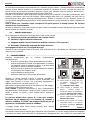
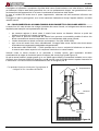
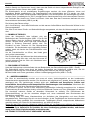
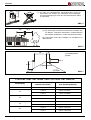
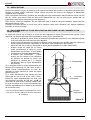
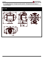
14. CONNECTING A CHIMNEY OR OPEN FURNACE TO THE FLUE
The smoke channel is the section of tube that connects the product to the flue, in the connection these
simple but very important principles must be followed:
• for no reason must the smoke channel be used with a diameter lower than that of the neck of the
outlet with which the product is fitted;
• each metre of horizontal route of the smoke channel causes a small leak of charge which should be
compensated for by raising the flue;
• the horizontal section must never be higher than 2 m (UNI 10683-2005);
• each bend of the smoke channel considerably reduces the draught of the flue which must be
compensated for by raising it suitably;
• the UNI 10683-2005 Regulation –Italy requires that the bends or variations of direction must in no
case be greater than 2 including the emission into the flue.
Wanting to use the flue of a chimney or open furnace, it will be necessary to close the hood hermetically
below the inlet point of the smoke channel pos. A Picture 11.
If the flue is too large (e.g. cm 30x40 or 40x50) it is necessary to duct it with a stainless steel tube of at
least 200 mm of diameter, pos. B taking care to close the space between the tube itself and the flue
immediately below the chimney cap pos. C.
For any further information, please contact your Dealer!
Picture 11
C - Plugging
A – Hermetic closure
Inspection
hatch
B
Page is loading ...
Page is loading ...
Page is loading ...
Page is loading ...
Page is loading ...
Page is loading ...
Page is loading ...
Page is loading ...
Page is loading ...
Page is loading ...
Page is loading ...
Page is loading ...
Page is loading ...
Page is loading ...
Page is loading ...
Page is loading ...
Page is loading ...
Page is loading ...
Page is loading ...
Page is loading ...
Page is loading ...
Page is loading ...

ELLIPSE
50 7196901 Rev.09 – IT – EN – DE – FR
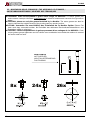
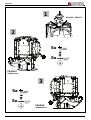
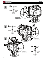
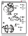
15. MONTAGGIO DELLE CERAMICHE / THE ASSEMBLY OF CERAMICS /
KACHELNBAUANLEITUNGEN / MONTAGE DES CÉRAMIQUES
ATTENZIONE: usare esclusivamente il grasso della siringa La NORDICA. Lo stesso grasso può
anche essere usato per lubrificare moderatamente le rotelle di rotazione del raccordo fumi girevole in
ghisa .
ATTENTION: please use only the grease furnished by La Nordica. The same grease can also be
used to lubricate the rotation wheels of the pivoting cast-iron smoke junction.
ACHTUNG: Verwenden Sie ausschließlich das Schmierfett der La Nordica Spritze. Dieses Fett
kann auch dazu verwendet werden, die Drehräder des drehbaren Rauchrohranschlussstückes aus
Gusseisen mäßig zu schmieren.
ATTENTION : utiliser uniquement de la graisse provenant d’une seringue de La NORDICA. Cette
même graisse pourra également servir à lubrifier avec modération les molettes de rotation du raccord
de fumée rotatif en fonte
NON FORNITO
NOT SUPPLIED
NICHT IM LIEFERUMFANG
PAS FOURNIS
8x 24x 26x
Page is loading ...
Page is loading ...
Page is loading ...
Page is loading ...

ELLIPSE
7196901 Rev.09 – IT – EN – DE – FR 55
16. SCHEDA TECNICA / TECHNICAL DATA SHEETS / TECHNISCHE PROTOKOLLE /
FICHE TECHNIQUE
ELLIPSE

GIANNI RAGUSA
Amministratore delegato - Managing Director
Geschäftsführer - Administrateur délégué
La NORDICA S.p.A. Via Summano,104 – 36030 MONTECCHIO PRECALCINO (VICENZA) – Tel. 0445 804000 – Fax 0445 804040 Capitale Sociale Euro 8.000.000 I.v. – R.E.A. n.
104860/VI – Codice Fiscale e Partita IVA e Registro Imprese 0182840249 M. VI 007364
http://www.lanordica-extraame.com – e-mail:[email protected]
La NORDICA S.p.A.
Via Summano,104 - 36030 Montecchio Precalcino (VICENZA)
+39 0445 804000 - Fax +39 0445 804040
Montecchio Precalcino (VICENZA)
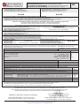
DICHIARAZIONE DI PRESTAZIONE In base al regolamento (UE) n. 305/2011
LEISTUNGSERKLÄRUNG Gemäß der Verordnung (EG) Nr. 305/2011
DECLARATION OF PERFORMANCE According to Regulation (EU) No. 305/2011
DÉCLARATION DE PERFORMANCE Selon le règlement (UE) n° 305/2011
N. 089
1. Codice identicativo unico del prodotto-tipo:
Unique identier code for product-type
Eindeutiger Identikationscode des Produktes
Typ - Code d’identication unique du produit-type
2. Modello e/o n. lotto e/o n. serie (Art.11-4) :
Model and/or batch no. and/or series no. (Article 11-4)
Modell und/oder Losnr. und/oder Serien nr. (Art.11-4)
Modèle et/ou n° de lot et/ou n° de série (Art. 11-4)
ELLIPSE ELLIPSE
3. Usi previsti del prodotto conformemente alla relativa specica tecnica armonizzata:
Intended uses of the product in accordance with the applicable harmonised technical specication
Vorgesehene Verwendung des Produkts in Übereinstimmung mit der geltenden harmonisierten technischen Spezikation
Utilisation prévue du produit conformément aux spécications techniques harmonisées correspondantes
Stufe per il riscaldamento domestico alimentato con combustibile solido, senza la produzione di acqua calda.
Chimney for domestic heating, fuelled with solid fuel , without hot water production.
Kaminofen für Raumheizung für feste Brennstoffe / ohne Warmwasserbereitung.
Poêle-cheminées de chauffage domestique alimenté au combustible solide , sans production d’eau chaude.
4. Nome o marchio registrato del fabbricante (Art 11-5):
Name or trademark of the manufacturer (Article 11-5)
Name oder registriertes Warenzeichen des Herstellers (Art 11-5)
Nom ou marque enregistrée du fabricant (Art. 11-5)
5. Nome e indirizzo del mandatario (Art 12-2)
Name and address of the agent (Article 12-2)
Name und Adresse des Auftragnehmers (Art 12-2)
Nom et adresse du mandataire (Art. 12-2)
6. Sistema di valutazione e verica della costanza della prestazione (Allegato 5):
Assessment and verication system for constancy of performance (Annex 5)
System zur Bewertung und Überprüfung der Leistungsbeständigkeit (Anlage 5)
Système d’évaluation et contrôle de la constance de performance (Annexe 5)
System 3
7. Laboratorio noticato :
Laboratory notied
Benanntes Labor
Laboratoire notié
RRF 1625 - RRF Rhein-Ruhr Feuerstätten
Prüfstelle GmbH
Am Technologie Park 1 D-45307 ESSEN
Numero rapporto di prova (in base al System 3)
Test report number (based on System 3)
Nummer des Prüfberichts (gemäß System 3)
Numéro du rapport d’essai (selon le System 3)
40 09 2032
8. Prestazioni dichiarate - Services declare - Erklärte Leistungen - Performance déclarée
Specica tecnica armonizzata Harmonised technical specications - Harmonisierte technische Spezikation -
Spécications techniques harmonisées
EN 13240:2001/A2:2004/AC:2007
Caratteristiche essenziali - Essential features - Wesentliche Merkmale - Caractéristiques essentielles
Prestazione - Services - Leistungen
- Performance
Resistenza al fuoco - Resistance to re - Feuerbeständigkeit - Résistance au feu
A1
Distanza da materiali Combustibili
Distance from combustible material
Abstand von brennbarem Material
Distance de sécurité aux matériaux
combustibles
Distanza minima, in mm - Minimum distance, in mm - Mindestabstand, in mm - Distance minimum, en mm
retro - retro – Rückseite - arrière =
lato - side - Seite - côté =
softto
- bottom - Unterseite - fond =
fronte – front – Vorderseite - avant =
suolo - ground - Boden - sol =
100
100
-
1000
-
Rischio fuoriuscita combustibile - Fuel leakage risk - Gefahr Brennstoffaustritt - Risque de fuite de combustible Conforme - Compliant - Konform - Conforme
Temperatura superciale - Surface temperature - Oberächentemperatur - Température de surface Conforme - Compliant - Konform - Conforme
Sicurezza elettrica - Electrical safety - Elektrische Sicherheit - Sécurité électrique Conforme - Compliant - Konform - Conforme
Accessibilità e pulizia - Accessibility and cleaning - Zugänglichkeit und Reinigung - Facilité d’accès et nettoyage Conforme - Compliant - Konform - Conforme
Emissioni prodotti combustione (CO) - Combustion products emissions (CO) - Emission von Verbrennungsprodukten (CO) - Émission des produits de
combustion (CO)
CO [0.09%]
Massima pressione di esercizio - Maximum operating pressure - Maximaler Betriebsdruck - Pression maximale de service - bar
Resistenza meccanica (per supportare il camino) - Mechanical strength (to support the replace) - Mechanische Festigkeit (um den Kamin zu tragen) -
Résistance mécanique (pour soutenir la cheminée)
NDP
Prestazioni termiche
Thermal performance
Thermische Leistungen
Performance thermique
Potenza nominale - Rated power - Nennleistung - Puissance nominale
Potenza resa all’ambiente - Power output to the environment - Der Umgebung gelieferte Leistung- Puissance rendue au milieu
Potenza ceduta all’acqua - Power transferred to water - DemWasser gelieferte Leistung - Puissance rendue à l’eau
8 kW
8 kW
- kW
Rendimento - Yield - Wirkungsgrad - Rendement η [78.1%]
Temperatura fumi - Fume temperature - Rauchgastemperatur - Température des fumées T [312 °C]
9. La prestazione del prodotto di cui ai punti 1 e 2 è conforme alla prestazione dichiarata di cui al punto 8.
The performance of the product referred to in points 1 and 2 is consistent with the declared performance in point 8.
Die Leistung des Produktes gemäß den Punkten 1 und 2 entspricht der erklärten Leistung nach Punkt 8.
La performance du produit citée aux points 1 et 2 est conforme à la performance déclarée au point 8
Si rilascia la presente dichiarazione di prestazione sotto la responsabilità esclusiva del fabbricante di cui al punto 4.
This declaration of performance is issued under the manufacturer’s sole responsibility referred to in point 4.
Die vorliegende Leistungserklärung wird unter ausschließlicher Verantwortung des Herstellers erlassen, siehe Punkt 4.
Cette déclaration de performance est délivrée sous la responsabilité exclusive du fabricant cité au point 4.
09/06/2013
................................................
(Data e luogo di emissione - place and date of issue -
Ort und Datum der Ausstellung - Date et lieu d’émission )
(nome, posizione e rma - name, function and signature -
Positionsbezeichnung - Nom, Fonction et signature)

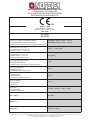
INFORMAZIONI MARCATURA CE
CE MARKING INFORMATION
CE AUSZEICHNUNGSINFORMATIONEN
INFORMATIONS MARQUAGE CE
Distanza minima da materiali inammabili
Distance to adjacent combustible materials
Mindestabstand zu brennbaren Materialen
Distance minimum par rapport aux matériaux inammables
Laterale / Lateral / Seiten 100 mm
Posteriore / Rear / Hinten 100 mm
Emissione di CO (13 % O
2
)
Emission of CO (13 % O
2
)
CO-Ausstoss bez.auf (13 % O
2
)
Émission de CO (13 % O
2
)
Emissioni polveri (13 % O
2
)
Dust emissions (13 % O
2
)
Staubemissionen (13 % O
2
)
Émission de poudres (13 % O
2
)
Massima pressione idrica di esercizio ammessa
Maximum operating pressure
Maximale Betriebsdruck
Pression hydrique de service maximum autorisée
Temperatura gas di scarico
Flue gas temperature
Abgastemperatur
Température gaz d’échappement
Potenza termica nominale
Thermal output
Nennheizleistung
Puissance thermique nominale
Rendimento
Energy efciency
Wirkungsgrad
Rendement
Tipi di combustibile
Fuel types
Brennstoffarten
Types de combustible
LEGNA – WOOD – HOLZ – BOIS
La NORDICA S.p.A. Via Summano,104 – 36030 MONTECCHIO PRECALCINO (VICENZA) – Tel. 0445 804000 – Fax 0445 804040 Capitale Sociale Euro 8.000.000 I.v. – R.E.A. n.
104860/VI – Codice Fiscale e Partita IVA e Registro Imprese 0182840249 M. VI 007364
http://www.lanordica-extraame.com – e-mail:[email protected]
LA NORDICA S.p.A.
09
EN 13240
ELLIPSE
0.09 % - 1125 mg/Nm
3
23 mg/Nm
3
- bar
312 °C
8 Kw
78.1 %
VKF - AEAI Nr.
Nr.19352
SINTEF Nr.
15a B-VG Nr.
RRF-40 09 2032
|
DOP nr. 089
Ente noticato - Notied body
Benanntes Labor - Laboratoire notié
RRF 1625
09
Page is loading ...
Page is loading ...
Page is loading ...
-
 1
1
-
 2
2
-
 3
3
-
 4
4
-
 5
5
-
 6
6
-
 7
7
-
 8
8
-
 9
9
-
 10
10
-
 11
11
-
 12
12
-
 13
13
-
 14
14
-
 15
15
-
 16
16
-
 17
17
-
 18
18
-
 19
19
-
 20
20
-
 21
21
-
 22
22
-
 23
23
-
 24
24
-
 25
25
-
 26
26
-
 27
27
-
 28
28
-
 29
29
-
 30
30
-
 31
31
-
 32
32
-
 33
33
-
 34
34
-
 35
35
-
 36
36
-
 37
37
-
 38
38
-
 39
39
-
 40
40
-
 41
41
-
 42
42
-
 43
43
-
 44
44
-
 45
45
-
 46
46
-
 47
47
-
 48
48
-
 49
49
-
 50
50
-
 51
51
-
 52
52
-
 53
53
-
 54
54
-
 55
55
-
 56
56
-
 57
57
-
 58
58
-
 59
59
-
 60
60


La Nordica Ellipse Owner's manual
- Category
- Stoves
- Type
- Owner's manual
Ask a question and I''ll find the answer in the document
Finding information in a document is now easier with AI
in other languages
Related papers
-
La Nordica Concita Owner's manual
-
-
La Nordica ESTER FORNO EVO Owner's manual
-
-
-
-
-
-
Nordica-Extraflame Anthea Silk Vogue Owner's manual
-
La Nordica Gemma Forno Owner's manual
Other documents
-
Nordica Padova Instructions For Installation, Use And Maintenance Manual
-
Piazzetta Piazzetta 610 HT Datasheet
-
 IKL Mercury User manual
-
-
Castorama 98BASE8-GCA User manual
-
Blaze ES 9 Installation guide
-
Ravelli THOR Use and Maintenance Manual
-
Hergom DIVA MII PRISMA Installation, Use And Maintenance Instructions
-
 Olimpia Splendid MIA 2 7.5 User manual
-
 Olimpia Splendid MIA 2-11 User manual


