

EB000000
YZF-R6
SERVICE MANUAL
1998 by Yamaha Motor Co., Ltd.
First edition, August 1998
All rights reserved. Any reproduction or
unauthorized use without the written
permission of Yamaha Motor Co., Ltd.
is expressly prohibited.

NOTE:
WARNING
CAUTION:
EB001000
NOTICE
This manual was produced by the Yamaha Motor Company, Ltd. primarily for use by Yamaha dealers
and their qualified mechanics. it is not possible to include all the knowledge of a mechanic in one manu-
al. Therefore, anyone who uses this book to perform maintenance and repairs on Yamaha vehicles
should have a basic understanding of mechanics and the techniques to repair these types of vehicles.
Repair and maintenance work attempted by anyone without this knowledge is likely to render the ve-
hicle unsafe and unfit for use.
Yamaha Motor Company, Ltd. is continually striving to improve all of its models. Modifications and sig-
nificant changes in specifications or procedures will be forwarded to all authorized Yamaha dealers
and will appear in future editions of this manual where applicable.
Designs and specifications are subject to change without notice.
EB002000
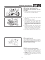
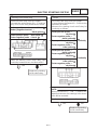
IMPORTANT MANUAL INFORMATION
Particularly important information is distinguished in this manual by the following.
The Safety Alert Symbol means ATTENTION! BECOME ALERT! YOUR
SAFETY IS INVOLVED!
Failure to follow WARNING instructions could result in severe injury or death to
the motorcycle operator, a bystander or a person checking or repairing the mo-
torcycle.
A CAUTION indicates special precautions that must be taken to avoid damage
to the motorcycle.
NOTE: A NOTE provides key information to make procedures easier or clearer.

126
4
5
7
3
8
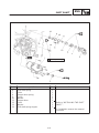
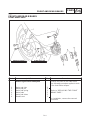
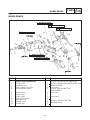
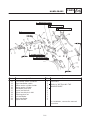
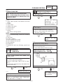
EB003000
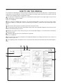
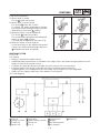
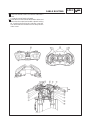
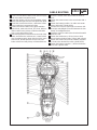
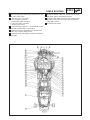
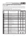
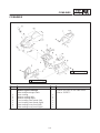
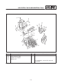
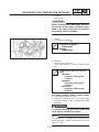
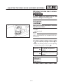
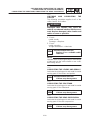
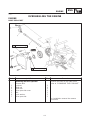
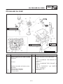
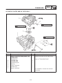
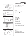
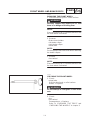
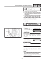
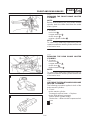
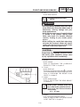
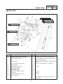
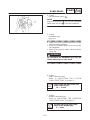
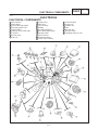
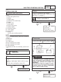
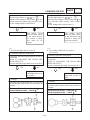
HOW TO USE THIS MANUAL
This manual is intended as a handy, easy-to-read reference book for the mechanic. Comprehensive
explanations of all installation, removal, disassembly, assembly, repair and check procedures are laid
out with the individual steps in sequential order.
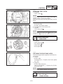
1
The manual is divided into chapters. An abbreviation and symbol in the upper right corner of each
page indicate the current chapter.
Refer to “SYMBOLS”.
2
Each chapter is divided into sections. The current section title is shown at the top of each page,
except in Chapter 3 (“PERIODIC CHECKS AND ADJUSTMENTS”), where the sub-section title(-s) ap-
pears.
3
Sub-section titles appear in smaller print than the section title.
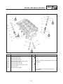
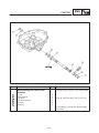
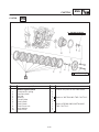
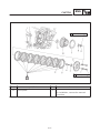
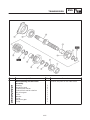
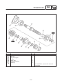
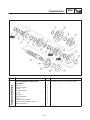
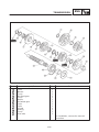
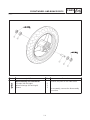
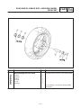
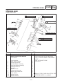
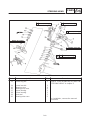
4
To help identify parts and clarify procedure steps, there are exploded diagrams at the start of each
removal and disassembly section.
5
Numbers are given in the order of the jobs in the exploded diagram. A circled number indicates a
disassembly step.
6
Symbols indicate parts to be lubricated or replaced.
Refer to “SYMBOLS”.
7
A job instruction chart accompanies the exploded diagram, providing the order of jobs, names of
parts, notes in jobs, etc.
8
Jobs requiring more information (such as special tools and technical data) are described sequen-
tially.

22
1
3
5
7
9
2
4
8
6
24 25
2321
19 2018
16 1715
1413
11 12
10
GEN
INFO
SPEC
ENG
CARB
ELECCHAS
COOL
CHK
ADJ
TRBL
SHTG
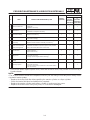
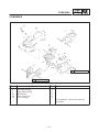
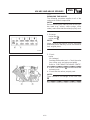
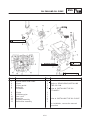
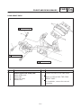
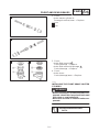
EB004000
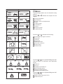
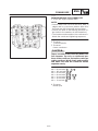
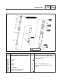
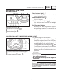
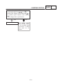
SYMBOLS
The following symbols are not relevant to every
vehicle.
Symbols
1
to
9
indicate the subject of each
chapter.
1
General information
2
Specifications
3
Periodic checks and adjustments
4
Engine
5
Cooling system
6
Carburetor(-s)
7
Chassis
8
Electrical system
9
Troubleshooting
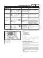
Symbols
10
to
17
indicate the following.
10
Serviceable with engine mounted
11
Filling fluid
12
Lubricant
13
Special tool
14
Tightening torque
15
Wear limit, clearance
16
Engine speed
17
Electrical data
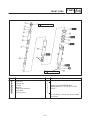
Symbols
18
to
23
in the exploded diagrams indi-
cate the types of lubricants and lubrication
points.
18
Engine oil
19
Gear oil
20
Molybdenum disulfide oil
21
Wheel bearing grease
22
Lithium soap base grease
23
Molybdenum disulfide grease
Symbols
24
to
25
in the exploded diagrams indi-
cate the following.
24
Apply locking agent (LOCTITE
)
25
Replace the part

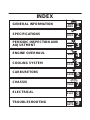
GENERAL INFORMATION
SPECIFICATIONS
PERIODIC INSPECTION AND
ADJUSTMENT
ENGINE OVERHAUL
COOLING SYSTEM
CARBURETORS
CHASSIS
ELECTRICAL
TROUBLESHOOTING
GEN
INFO
1
SPEC
2
3
ENG
4
COOL
5
CARB
6
CHAS
7
ELEC
8
TRBL
SHTG
9
CHK
ADJ
INDEX

GEN
INFO
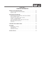
CHAPTER 1.
GENERAL INFORMATION
MOTORCYCLE IDENTIFICATION 1-1. . . . . . . . . . . . . . . . . . . . . . . . . . . . . . .
VEHICLE IDENTIFICATION NUMBER 1-1. . . . . . . . . . . . . . . . . . . . . . . . .
MODEL CODE 1-1. . . . . . . . . . . . . . . . . . . . . . . . . . . . . . . . . . . . . . . . . . . . .
IMPORTANT INFORMATION 1-2. . . . . . . . . . . . . . . . . . . . . . . . . . . . . . . . . . . .
PREPARATION FOR REMOVAL AND DISASSEMBLY 1-2. . . . . . . . . .
REPLACEMENT PARTS 1-2. . . . . . . . . . . . . . . . . . . . . . . . . . . . . . . . . . . . .
GASKETS, OIL SEALS AND O-RINGS 1-2. . . . . . . . . . . . . . . . . . . . . . . .
USING A DYNAMOMETER 1-3. . . . . . . . . . . . . . . . . . . . . . . . . . . . . . . . . .
LOCK WASHERS/PLATES AND COTTER PINS 1-3. . . . . . . . . . . . . . . .
BEARINGS AND OIL SEALS 1-3. . . . . . . . . . . . . . . . . . . . . . . . . . . . . . . . .
CIRCLIPS 1-3. . . . . . . . . . . . . . . . . . . . . . . . . . . . . . . . . . . . . . . . . . . . . . . . . .
CHECKING THE CONNECTIONS 1-4. . . . . . . . . . . . . . . . . . . . . . . . . . . . . . .
FEATURES 1-5. . . . . . . . . . . . . . . . . . . . . . . . . . . . . . . . . . . . . . . . . . . . . . . . . . .
AIR INTAKE SYSTEM 1-5. . . . . . . . . . . . . . . . . . . . . . . . . . . . . . . . . . . . . . .
THERMOSTAT 1-5. . . . . . . . . . . . . . . . . . . . . . . . . . . . . . . . . . . . . . . . . . . . .
IGNITION SYSTEM 1-6. . . . . . . . . . . . . . . . . . . . . . . . . . . . . . . . . . . . . . . . .
SPECIAL TOOLS 1-8. . . . . . . . . . . . . . . . . . . . . . . . . . . . . . . . . . . . . . . . . . . . . .

1-1
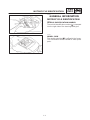
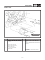
MOTORCYCLE IDENTIFICATION
GEN
INFO
EB100000
GENERAL INFORMATION
MOTORCYCLE IDENTIFICATION
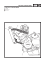
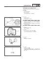
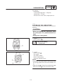
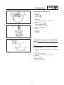
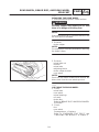
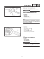
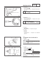
EB100010
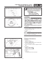
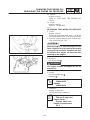
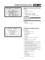
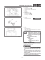
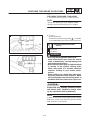
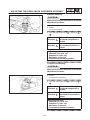
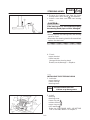
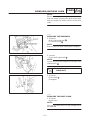
VEHICLE IDENTIFICATION NUMBER
The vehicle identification number
1
is stamped
into the right side of the steering head pipe.
EB100020
MODEL CODE
The model code label
1
is affixed to the frame.
This information will be needed to order spare
parts.

1-2
IMPORTANT INFORMATION
GEN
INFO
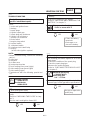
EB102000
IMPORTANT INFORMATION
PREPARATION FOR REMOVAL AND DIS-
ASSEMBLY
1. Before removal and disassembly, remove all
dirt, mud, dust, and foreign material.
2. Use only the proper tools and cleaning
equipment.
Refer to “SPECIAL TOOLS”.
3. When disassembling, always keep mated
parts together. This includes gears, cylin-
ders, pistons and other parts that have been
“mated” through normal wear. Mated parts
must always be reused or replaced as an as-
sembly.
4. During disassembly, clean all of the parts
and place them in trays in the order of disas-
sembly. This will speed up assembly and al-
low for the correct installation of all parts.
5. Keep all parts away from any source of fire.
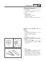
EB102010
REPLACEMENT PARTS
Use only genuine Yamaha parts for all replace-
ments. Use oil and grease recommended by
Yamaha for all lubrication jobs.
Other brands may be similar in function and ap-
pearance, but inferior in quality.
EB102020
GASKETS, OIL SEALS AND O-RINGS
1. When overhauling the engine, replace all
gaskets, seals, and O-rings. All gasket sur-
faces, oil seal lips, and O-rings must be
cleaned.
2. During reassembly, properly oil all mating
parts and bearings and lubricate the oil seal
lips with grease.

1-3
IMPORTANT INFORMATION
GEN
INFO
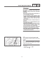
CAUTION:
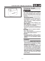
USING A DYNAMOMETER
The YZF-R6 has a carbon muffler that may
change color when exposed to high tempera-
tures. Therefore, when using a dynamometer
always use a fan to cool the muffler.
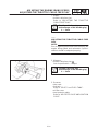
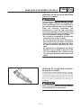
EB102030
LOCK WASHERS/PLATES AND COTTER
PINS
After removal, replace all lock washers/plates
1
and cotter pins. After the bolt or nut has been
tightened to specification, bend the lock washer
tabs and the cotter pin ends along a flat of the
bolt or nut.
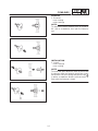
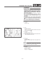
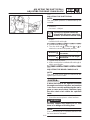
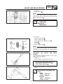
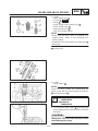
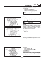
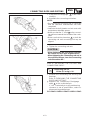
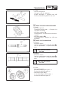
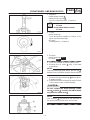
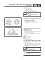
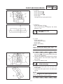
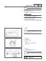
EB102040
BEARINGS AND OIL SEALS
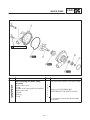
1. Install bearings and oil seals so that the
manufacturer’s marks or numbers are vis-
ible. When installing oil seals, lubricate the
oil seal lips with a light coat of lithium soap
base grease. Oil bearings liberally when
installing, if appropriate.
1
Oil seal
Do not spin the bearing with compressed air
because this will damage the bearing sur-
faces.
1
Bearing
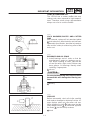
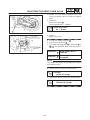
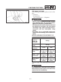
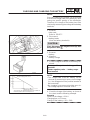
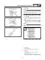
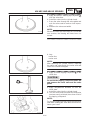
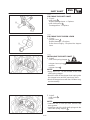
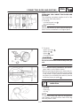
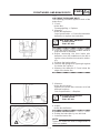
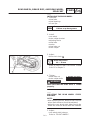
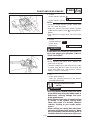
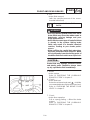
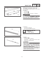
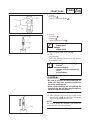
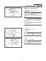
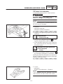
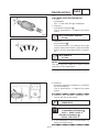
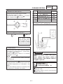
EB102050
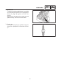
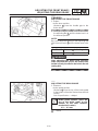
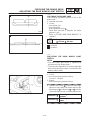
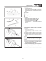
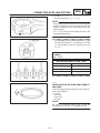
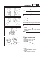
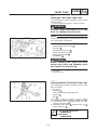
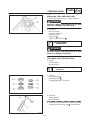
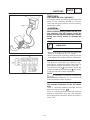
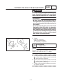
CIRCLIPS
Before reassembly, check all circlips carefully
and replace damaged or distorted circlips. Al-
ways replace piston pin clips after one use.
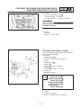
When installing a circlip
1
, make sure that the
sharp-edged corner
2
is positioned opposite
the thrust
3
that the circlip receives.
4
Shaft

1-4
CHECKING THE CONNECTIONS
GEN
INFO
NOTE:
NOTE:
NOTE:
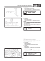
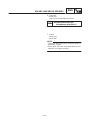
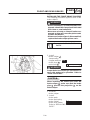
EB103000
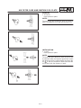
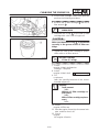
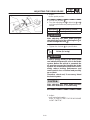
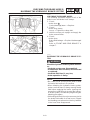
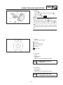
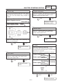
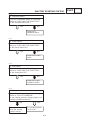
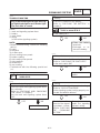
CHECKING THE CONNECTIONS
Check the leads, couplers, and connectors for
stains, rust, moisture, etc.
1. Disconnect:
lead
coupler
connector
2. Check:
lead
coupler
connector
Moisture Dry with an air blower.
Rust/stains Connect and disconnect sev-
eral times.
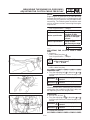
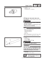
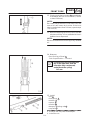
3. Check:
all connections
Loose connection Connect properly.
If the pin
1
on the terminal is flattened, bend it
up.
4. Connect:
lead
coupler
connector
Make sure that all connections are tight.
5. Check:
continuity
(with the pocket tester)
Pocket tester
90890-03112
If there is no continuity, clean the terminals.
When checking the wire harness, perform
steps (1) to (3).
As a quick remedy, use a contact revitalizer
available at most part stores.

1-5
FEATURES
GEN
INFO
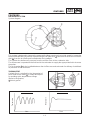
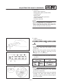
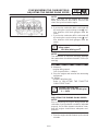
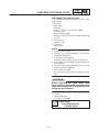
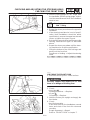
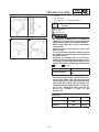
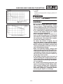
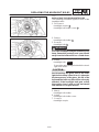
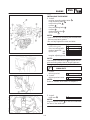
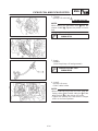
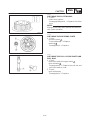
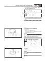
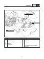
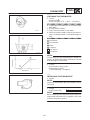
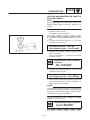
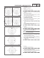
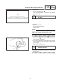
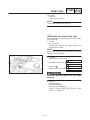
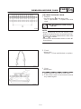
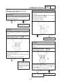
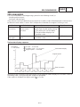
Former thermostat
Temperature
Time
New thermostat
Temperature
Time
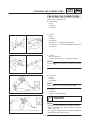
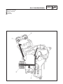
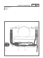
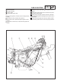
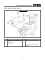
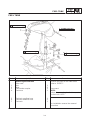
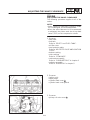
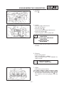
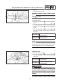
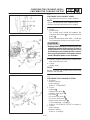
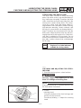
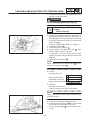
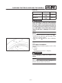
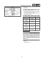
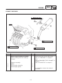
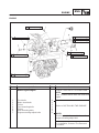
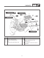
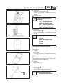
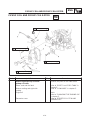
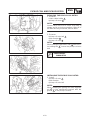
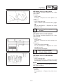
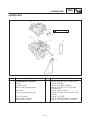
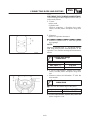
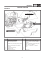
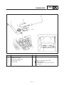
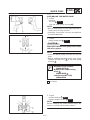
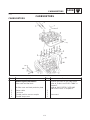
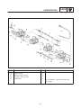
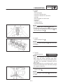
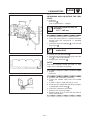
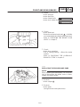
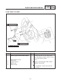
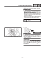
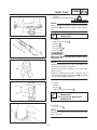
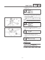
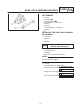
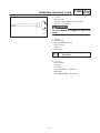
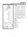
FEATURES
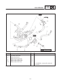
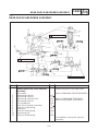
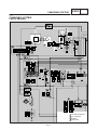
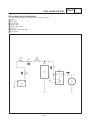
AIR INTAKE SYSTEM
System diagram
This system is designed to improve the power while riding a motorcycle at a high speed by increasing
the air intake efficiency by means of pressurizing the air filter case
2
where the air is taken in via the air
duct
1
from the air intake port located under the headlight.
The system also delivers air pressure from the air filter case to the carburetor side.
The air pressure is operated to the fuel level in the carburetor to supply the appropriate fuel to increase
the power.
The air chamber
3
is also installed between the air filter case and carburetor for delivery of stabilized
air pressure to the carburetor.
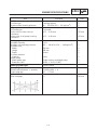
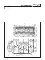
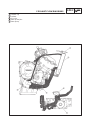
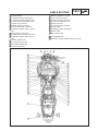
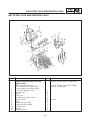
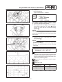
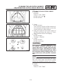
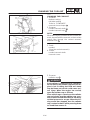
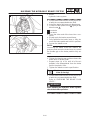
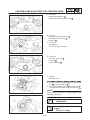
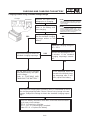
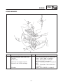
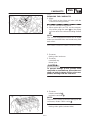
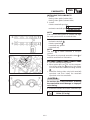
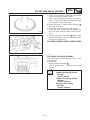
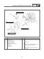
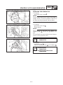
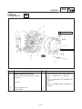
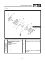
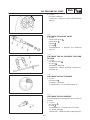
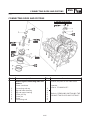
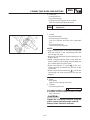
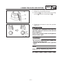
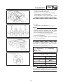
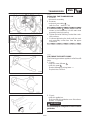
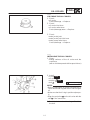
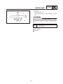
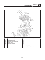
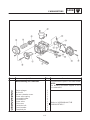
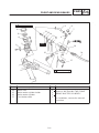
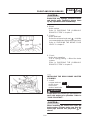
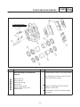
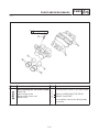
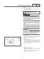
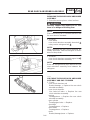
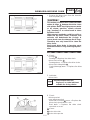
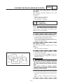
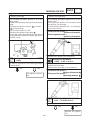
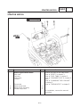
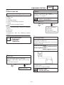
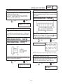
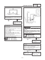
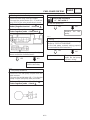
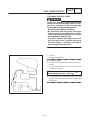
THERMOSTAT
Coolant flow is controlled by the thermostat of
which flow control valve
1
is newly developed
for avoiding quick temperature change.
(Refer to the graphs)
2
Notch groove

1-6
FEATURES
GEN
INFO
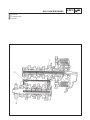
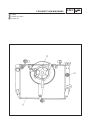
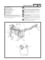
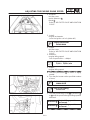
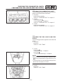
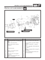
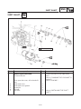
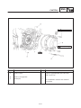
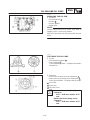
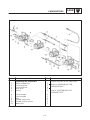
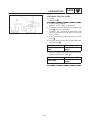
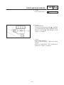
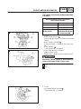
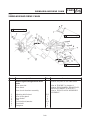
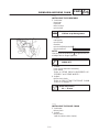
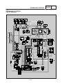
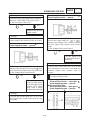
1) 2)
3)
4)
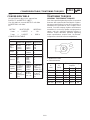
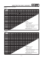
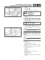
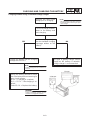
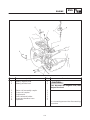
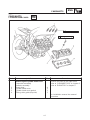
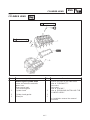
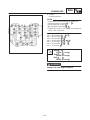
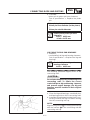
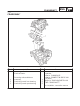
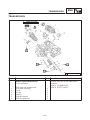
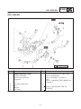
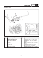
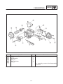
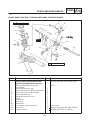
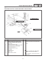
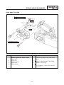
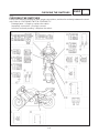
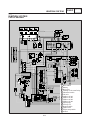
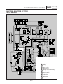
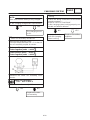
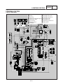
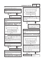
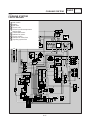
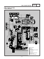
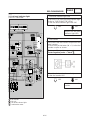
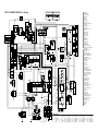
1 CDI unit
2 Voltage converter
3 Condenser
4 Ignition coil
5 Spark plug
6 Ignition timing controller
7 Pickup coil
8 T. P. S.
9 Speed sensor
10 Battery
11 Rectifier/regulator
12 AC magneto
13 Stator coil
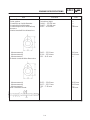
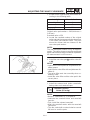
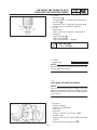
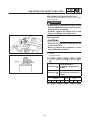
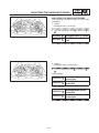
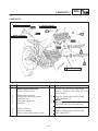
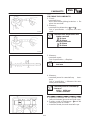
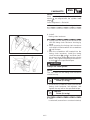
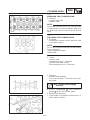
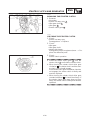
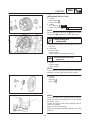
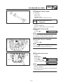
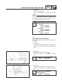
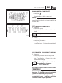
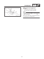
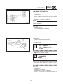
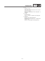
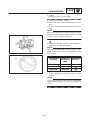
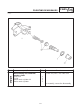
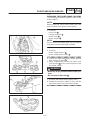
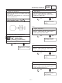
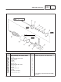
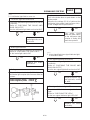
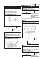
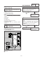
Flow control operation
1) When valve is closed
The lip
1
seals the coolant.
2) When valve is set as low-lift
The 2nd lip
2
seals the coolant.
To reduce the water temperature change,
the coolant starts flowing through the notch
depending on its area at
a
section.
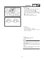
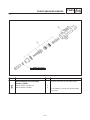
3) When the valve is set as middle-lift
The 3rd lip
3
seals the coolant.
The coolant flows through the notch depend-
ing on its area at
b
section.
This flow rate is larger than the case of 2).
4) When the valve is set as high-lift
In the same way as the regular thermostat
control, the coolant flows through clearance
c
between the valve and flange.
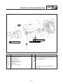
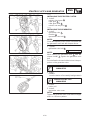
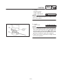
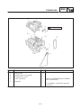
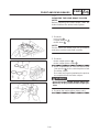
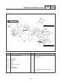
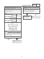
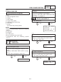
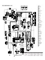
IGNITION SYSTEM
1. DC CDI
1) Features
* Battery is used as the power source.
* Stabilized spark performance is provided in the range from a low speed to high speed since the
battery is used as the power source.
* Compact AC magneto design is possible since the source coil is unnecessary.
* Compact ignition coil design is possible since the condenser stores electricity.
Plug top ignition coil is equipped in which the plug cap and ignition coil are integrated.
* Stator coil can supply power even if the battery is running out.
2) Circuit diagram

1-7
FEATURES
GEN
INFO
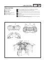
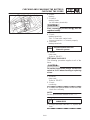
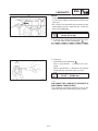
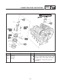
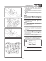
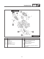
2. Ignition coil
Compact and right weight design is provided
since the plug top ignition coil is equipped in
which the plug cap ignition coil are inte-
grated.
High tension cord was cut an end to use and
ignition energy loss has become lower.
3. Spark plug
The 2-pole spark plug is applied to improve
the ignition quality and combustion efficien-
cy.

1-8
SPECIAL TOOLS
GEN
INFO
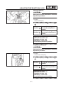
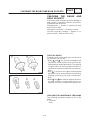
EB104000
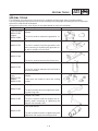
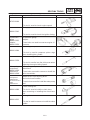
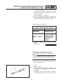
SPECIAL TOOLS
The following special tools are necessary for complete and accurate tune-up and assembly.
Use only the appropriate special tools as this will help prevent damage caused by the use of inappropri-
ate tools or improvised techniques.
When placing an order, refer to the list provided below to avoid any mistakes.
Tool No.
Tool name/Function Illustration
Flywheel puller
90890-01362
Adapter
90890-04089
Flywheel puller
Adapter
This tool is used to remove the generator ro-
tor.
90890-01701
Sheave holder
This tool is used to hold the generator rotor
when removing or installing the generator ro-
tor bolt or pickup coil rotor bolt.
90890-01304
Piston pin puller
This tool is used to remove the piston pins.
90890-01312
Fuel level gauge
This tool is used to measure the fuel level in
the float chamber.
Radiator cap
tester
90890-01325
Adapter
90890-01352
Radiator cap tester
Adapter
These tools are used to check the cooling
system.
90890-01403
Steering nut wrench
This tool is used to loosen or tighten the steer-
ing stem ring nuts.
90890-01425
Damper rod holder
This tool is used to hold the damper rod as-
sembly when loosening or tightening the
damper rod assembly bolt.
90890-01471
Pivot shaft wrench
This tool is used to loosen or tighten the pivot
adjust bolt and engine mount adjust bolt.

1-9
SPECIAL TOOLS
GEN
INFO
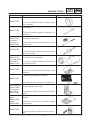
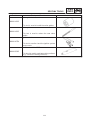
Tool No. Tool name/Function Illustration
90890-01426
Oil filter wrench
This tool is needed to loosen or tighten the oil
filter cartridge.
90890-01434
Rod holder
This tool is used to support the damper ad-
justing rod.
Rod puller
90890-01437
Rod puller
attachment
90890-01436
Rod puller
Rod puller attachment
These tools are used to pull up the front fork
damper rod.
90890-01441
Fork spring compressor
This tool is used to disassemble or assemble
the front fork legs.
Fork seal driver
90890-01376
Fork seal driver
attachment
90890-01374
Fork seal driver weight
Fork seal driver attachment
This tool is used to install the front fork’s oil
seal and dust seal.
90890-03008
Micrometer
This tool is used to measure the piston skirt
diameter.
90890-03017
Cylinder bore gauge (50~100mm)
This gauge is used to measure cylinder bore.
Vacuum gauge
90890-03094
Valve gauge
attachment
90890-03060
Vacuum gauge
Vacuum gauge attachment
This gauge is used to synchronize the carbu-
retors.
Compression
gauge
90890-03081
Adapter
90890-04136
Compression gauge
Adapter
These tools are used to measure engine
compression.
90890-03112
Pocket tester
This tool is used to check the electrical sys-
tem.

1-10
SPECIAL TOOLS
GEN
INFO
Tool No. Tool name/Function Illustration
90793-80009
Engine tachometer
This tool is used to check engine speed.
90890-03141
Timing light
This tool is used to check the ignition timing.
Oil pressure
gauge
90890-03153
Adapter
90890-03139
Oil pressure gauge
Adapter
These tools are used to measure engine oil
pressure.
90890-04044
Piston ring compressor
This tool is used to compress piston rings
when installing the cylinder.
90890-03158
Carburetor angle driver
This tool is used to turn the pilot screw when
adjusting the engine idling speed.
Valve spring
compressor
90890-04019
Attachment
90890-04108
Valve spring compressor
Attachment
These tools are used to remove or install the
valve assemblies.
Middle driven shaft
bearing driver
90890-04058
Mechanical seal in-
staller
90890-04078
Middle driven shaft bearing driver
Mechanical seal installer
These tools are used to install the water pump
seal.
90890-04086
Clutch holding tool
This tool is used to hold the clutch boss
when removing or installing the clutch boss
nut.
90890-04111
Valve guide remover
This tool is used to remove or install the valve
guides.

1-11
SPECIAL TOOLS
GEN
INFO
Tool No. Tool name/Function Illustration
90890-04112
Valve guide installer
This tool is used to install the valve guides.
90890-04113
Valve guide reamer
This tool is used to rebore the new valve
guides.
90890-06754
Ignition checker
This tool is used to check the ignition system
components.
90890-85505
Yamaha bond No. 1215
This bond is used to seal two mating surfaces
(e.g., crankcase mating surfaces).

SPEC
CHAPTER 2.
SPECIFICATIONS
GENERAL SPECIFICATIONS 2-1. . . . . . . . . . . . . . . . . . . . . . . . . . . . . . . . . . .
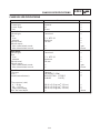
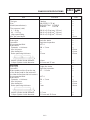
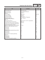
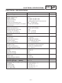
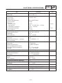
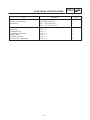
ENGINE SPECIFICATIONS 2-2. . . . . . . . . . . . . . . . . . . . . . . . . . . . . . . . . . . . .
CHASSIS SPECIFICATIONS 2-11. . . . . . . . . . . . . . . . . . . . . . . . . . . . . . . . . . . .
ELECTRICAL SPECIFICATIONS 2-15. . . . . . . . . . . . . . . . . . . . . . . . . . . . . . . .
CONVERSION TABLE 2-18. . . . . . . . . . . . . . . . . . . . . . . . . . . . . . . . . . . . . . . . . .
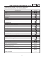
TIGHTENING TORQUES 2-18. . . . . . . . . . . . . . . . . . . . . . . . . . . . . . . . . . . . . . .
GENERAL TIGHTENING TORQUES 2-18. . . . . . . . . . . . . . . . . . . . . . . . . .
ENGINE TIGHTENING TORQUES 2-19. . . . . . . . . . . . . . . . . . . . . . . . . . . .
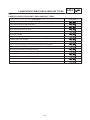
CHASSIS TIGHTENING TORQUES 2-22. . . . . . . . . . . . . . . . . . . . . . . . . . .
LUBRICATION POINTS AND LUBRICANT TYPES 2-23. . . . . . . . . . . . . . . .
ENGINE LUBRICATION POINTS AND LUBRICANT TYPES 2-23. . . . .
CHASSIS LUBRICATION POINTS AND LUBRICANT TYPES 2-24. . . .
OIL FLOW DIAGRAMS 2-25. . . . . . . . . . . . . . . . . . . . . . . . . . . . . . . . . . . . . . . . .
COOLANT FLOW DIAGRAMS 2-29. . . . . . . . . . . . . . . . . . . . . . . . . . . . . . . . . .
CABLE ROUTING 2-33. . . . . . . . . . . . . . . . . . . . . . . . . . . . . . . . . . . . . . . . . . . . .

2-1
GENERAL SPECIFICATIONS
SPEC
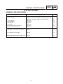
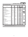
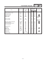
SPECIFICATIONS
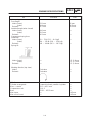
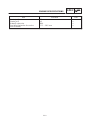
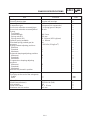
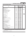
GENERAL SPECIFICATIONS
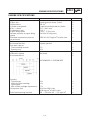
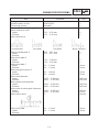
Item Standard Limit
Dimensions
Overall length
Overall width
Overall height
Seat height
Wheelbase
Minimum ground clearance
Minimum turning radius
2025 mm (except for NOR, SWE, FIN, AUS NZL)
2075 mm (for NOR, SWE, FIN, AUS, NZL)
690 mm
1105 mm
820 mm
1380 mm
135 mm
3400 mm
Weight
Wet (with oil and a full fuel tank)
Dry (without oil and fuel)
Maximum load (total of cargo, rider,
passenger, and accessories)
188 kg
169 kg
375 kg
Page is loading ...
Page is loading ...
Page is loading ...
Page is loading ...
Page is loading ...
Page is loading ...
Page is loading ...
Page is loading ...
Page is loading ...
Page is loading ...
Page is loading ...
Page is loading ...
Page is loading ...
Page is loading ...
Page is loading ...
Page is loading ...
Page is loading ...
Page is loading ...
Page is loading ...
Page is loading ...
Page is loading ...
Page is loading ...
Page is loading ...
Page is loading ...
Page is loading ...
Page is loading ...
Page is loading ...
Page is loading ...
Page is loading ...
Page is loading ...
Page is loading ...
Page is loading ...
Page is loading ...
Page is loading ...
Page is loading ...
Page is loading ...
Page is loading ...
Page is loading ...
Page is loading ...
Page is loading ...
Page is loading ...
Page is loading ...
Page is loading ...
Page is loading ...
Page is loading ...
Page is loading ...
Page is loading ...
Page is loading ...
Page is loading ...
Page is loading ...
Page is loading ...
Page is loading ...
Page is loading ...
Page is loading ...
Page is loading ...
Page is loading ...
Page is loading ...
Page is loading ...
Page is loading ...
Page is loading ...
Page is loading ...
Page is loading ...
Page is loading ...
Page is loading ...
Page is loading ...
Page is loading ...
Page is loading ...
Page is loading ...
Page is loading ...
Page is loading ...
Page is loading ...
Page is loading ...
Page is loading ...
Page is loading ...
Page is loading ...
Page is loading ...
Page is loading ...
Page is loading ...
Page is loading ...
Page is loading ...
Page is loading ...
Page is loading ...
Page is loading ...
Page is loading ...
Page is loading ...
Page is loading ...
Page is loading ...
Page is loading ...
Page is loading ...
Page is loading ...
Page is loading ...
Page is loading ...
Page is loading ...
Page is loading ...
Page is loading ...
Page is loading ...
Page is loading ...
Page is loading ...
Page is loading ...
Page is loading ...
Page is loading ...
Page is loading ...
Page is loading ...
Page is loading ...
Page is loading ...
Page is loading ...
Page is loading ...
Page is loading ...
Page is loading ...
Page is loading ...
Page is loading ...
Page is loading ...
Page is loading ...
Page is loading ...
Page is loading ...
Page is loading ...
Page is loading ...
Page is loading ...
Page is loading ...
Page is loading ...
Page is loading ...
Page is loading ...
Page is loading ...
Page is loading ...
Page is loading ...
Page is loading ...
Page is loading ...
Page is loading ...
Page is loading ...
Page is loading ...
Page is loading ...
Page is loading ...
Page is loading ...
Page is loading ...
Page is loading ...
Page is loading ...
Page is loading ...
Page is loading ...
Page is loading ...
Page is loading ...
Page is loading ...
Page is loading ...
Page is loading ...
Page is loading ...
Page is loading ...
Page is loading ...
Page is loading ...
Page is loading ...
Page is loading ...
Page is loading ...
Page is loading ...
Page is loading ...
Page is loading ...
Page is loading ...
Page is loading ...
Page is loading ...
Page is loading ...
Page is loading ...
Page is loading ...
Page is loading ...
Page is loading ...
Page is loading ...
Page is loading ...
Page is loading ...
Page is loading ...
Page is loading ...
Page is loading ...
Page is loading ...
Page is loading ...
Page is loading ...
Page is loading ...
Page is loading ...
Page is loading ...
Page is loading ...
Page is loading ...
Page is loading ...
Page is loading ...
Page is loading ...
Page is loading ...
Page is loading ...
Page is loading ...
Page is loading ...
Page is loading ...
Page is loading ...
Page is loading ...
Page is loading ...
Page is loading ...
Page is loading ...
Page is loading ...
Page is loading ...
Page is loading ...
Page is loading ...
Page is loading ...
Page is loading ...
Page is loading ...
Page is loading ...
Page is loading ...
Page is loading ...
Page is loading ...
Page is loading ...
Page is loading ...
Page is loading ...
Page is loading ...
Page is loading ...
Page is loading ...
Page is loading ...
Page is loading ...
Page is loading ...
Page is loading ...
Page is loading ...
Page is loading ...
Page is loading ...
Page is loading ...
Page is loading ...
Page is loading ...
Page is loading ...
Page is loading ...
Page is loading ...
Page is loading ...
Page is loading ...
Page is loading ...
Page is loading ...
Page is loading ...
Page is loading ...
Page is loading ...
Page is loading ...
Page is loading ...
Page is loading ...
Page is loading ...
Page is loading ...
Page is loading ...
Page is loading ...
Page is loading ...
Page is loading ...
Page is loading ...
Page is loading ...
Page is loading ...
Page is loading ...
Page is loading ...
Page is loading ...
Page is loading ...
Page is loading ...
Page is loading ...
Page is loading ...
Page is loading ...
Page is loading ...
Page is loading ...
Page is loading ...
Page is loading ...
Page is loading ...
Page is loading ...
Page is loading ...
Page is loading ...
Page is loading ...
Page is loading ...
Page is loading ...
Page is loading ...
Page is loading ...
Page is loading ...
Page is loading ...
Page is loading ...
Page is loading ...
Page is loading ...
Page is loading ...
Page is loading ...
Page is loading ...
Page is loading ...
Page is loading ...
Page is loading ...
Page is loading ...
Page is loading ...
Page is loading ...
Page is loading ...
Page is loading ...
Page is loading ...
Page is loading ...
Page is loading ...
Page is loading ...
Page is loading ...
Page is loading ...
Page is loading ...
Page is loading ...
Page is loading ...
Page is loading ...
Page is loading ...
Page is loading ...
Page is loading ...
Page is loading ...
Page is loading ...
Page is loading ...
Page is loading ...
Page is loading ...
Page is loading ...
Page is loading ...
Page is loading ...
Page is loading ...
Page is loading ...
Page is loading ...
Page is loading ...
Page is loading ...
Page is loading ...
Page is loading ...
Page is loading ...
Page is loading ...
Page is loading ...
Page is loading ...
Page is loading ...
Page is loading ...
Page is loading ...
Page is loading ...
Page is loading ...
Page is loading ...
Page is loading ...
Page is loading ...
Page is loading ...
Page is loading ...
Page is loading ...
Page is loading ...
Page is loading ...
Page is loading ...
Page is loading ...
Page is loading ...
Page is loading ...
Page is loading ...
Page is loading ...
Page is loading ...
Page is loading ...
Page is loading ...
Page is loading ...
Page is loading ...
Page is loading ...
Page is loading ...
Page is loading ...
Page is loading ...
Page is loading ...
Page is loading ...
Page is loading ...
Page is loading ...
Page is loading ...
Page is loading ...
Page is loading ...
Page is loading ...
Page is loading ...
Page is loading ...
Page is loading ...
Page is loading ...
Page is loading ...
Page is loading ...
Page is loading ...
Page is loading ...
Page is loading ...
Page is loading ...
Page is loading ...
Page is loading ...
Page is loading ...
Page is loading ...
Page is loading ...
Page is loading ...
Page is loading ...
Page is loading ...
Page is loading ...
Page is loading ...
Page is loading ...
Page is loading ...
Page is loading ...
Page is loading ...
Page is loading ...
Page is loading ...
Page is loading ...
Page is loading ...
Page is loading ...
Page is loading ...
Page is loading ...
Page is loading ...
Page is loading ...
Page is loading ...
Page is loading ...
Page is loading ...
Page is loading ...
Page is loading ...
-
 1
1
-
 2
2
-
 3
3
-
 4
4
-
 5
5
-
 6
6
-
 7
7
-
 8
8
-
 9
9
-
 10
10
-
 11
11
-
 12
12
-
 13
13
-
 14
14
-
 15
15
-
 16
16
-
 17
17
-
 18
18
-
 19
19
-
 20
20
-
 21
21
-
 22
22
-
 23
23
-
 24
24
-
 25
25
-
 26
26
-
 27
27
-
 28
28
-
 29
29
-
 30
30
-
 31
31
-
 32
32
-
 33
33
-
 34
34
-
 35
35
-
 36
36
-
 37
37
-
 38
38
-
 39
39
-
 40
40
-
 41
41
-
 42
42
-
 43
43
-
 44
44
-
 45
45
-
 46
46
-
 47
47
-
 48
48
-
 49
49
-
 50
50
-
 51
51
-
 52
52
-
 53
53
-
 54
54
-
 55
55
-
 56
56
-
 57
57
-
 58
58
-
 59
59
-
 60
60
-
 61
61
-
 62
62
-
 63
63
-
 64
64
-
 65
65
-
 66
66
-
 67
67
-
 68
68
-
 69
69
-
 70
70
-
 71
71
-
 72
72
-
 73
73
-
 74
74
-
 75
75
-
 76
76
-
 77
77
-
 78
78
-
 79
79
-
 80
80
-
 81
81
-
 82
82
-
 83
83
-
 84
84
-
 85
85
-
 86
86
-
 87
87
-
 88
88
-
 89
89
-
 90
90
-
 91
91
-
 92
92
-
 93
93
-
 94
94
-
 95
95
-
 96
96
-
 97
97
-
 98
98
-
 99
99
-
 100
100
-
 101
101
-
 102
102
-
 103
103
-
 104
104
-
 105
105
-
 106
106
-
 107
107
-
 108
108
-
 109
109
-
 110
110
-
 111
111
-
 112
112
-
 113
113
-
 114
114
-
 115
115
-
 116
116
-
 117
117
-
 118
118
-
 119
119
-
 120
120
-
 121
121
-
 122
122
-
 123
123
-
 124
124
-
 125
125
-
 126
126
-
 127
127
-
 128
128
-
 129
129
-
 130
130
-
 131
131
-
 132
132
-
 133
133
-
 134
134
-
 135
135
-
 136
136
-
 137
137
-
 138
138
-
 139
139
-
 140
140
-
 141
141
-
 142
142
-
 143
143
-
 144
144
-
 145
145
-
 146
146
-
 147
147
-
 148
148
-
 149
149
-
 150
150
-
 151
151
-
 152
152
-
 153
153
-
 154
154
-
 155
155
-
 156
156
-
 157
157
-
 158
158
-
 159
159
-
 160
160
-
 161
161
-
 162
162
-
 163
163
-
 164
164
-
 165
165
-
 166
166
-
 167
167
-
 168
168
-
 169
169
-
 170
170
-
 171
171
-
 172
172
-
 173
173
-
 174
174
-
 175
175
-
 176
176
-
 177
177
-
 178
178
-
 179
179
-
 180
180
-
 181
181
-
 182
182
-
 183
183
-
 184
184
-
 185
185
-
 186
186
-
 187
187
-
 188
188
-
 189
189
-
 190
190
-
 191
191
-
 192
192
-
 193
193
-
 194
194
-
 195
195
-
 196
196
-
 197
197
-
 198
198
-
 199
199
-
 200
200
-
 201
201
-
 202
202
-
 203
203
-
 204
204
-
 205
205
-
 206
206
-
 207
207
-
 208
208
-
 209
209
-
 210
210
-
 211
211
-
 212
212
-
 213
213
-
 214
214
-
 215
215
-
 216
216
-
 217
217
-
 218
218
-
 219
219
-
 220
220
-
 221
221
-
 222
222
-
 223
223
-
 224
224
-
 225
225
-
 226
226
-
 227
227
-
 228
228
-
 229
229
-
 230
230
-
 231
231
-
 232
232
-
 233
233
-
 234
234
-
 235
235
-
 236
236
-
 237
237
-
 238
238
-
 239
239
-
 240
240
-
 241
241
-
 242
242
-
 243
243
-
 244
244
-
 245
245
-
 246
246
-
 247
247
-
 248
248
-
 249
249
-
 250
250
-
 251
251
-
 252
252
-
 253
253
-
 254
254
-
 255
255
-
 256
256
-
 257
257
-
 258
258
-
 259
259
-
 260
260
-
 261
261
-
 262
262
-
 263
263
-
 264
264
-
 265
265
-
 266
266
-
 267
267
-
 268
268
-
 269
269
-
 270
270
-
 271
271
-
 272
272
-
 273
273
-
 274
274
-
 275
275
-
 276
276
-
 277
277
-
 278
278
-
 279
279
-
 280
280
-
 281
281
-
 282
282
-
 283
283
-
 284
284
-
 285
285
-
 286
286
-
 287
287
-
 288
288
-
 289
289
-
 290
290
-
 291
291
-
 292
292
-
 293
293
-
 294
294
-
 295
295
-
 296
296
-
 297
297
-
 298
298
-
 299
299
-
 300
300
-
 301
301
-
 302
302
-
 303
303
-
 304
304
-
 305
305
-
 306
306
-
 307
307
-
 308
308
-
 309
309
-
 310
310
-
 311
311
-
 312
312
-
 313
313
-
 314
314
-
 315
315
-
 316
316
-
 317
317
-
 318
318
-
 319
319
-
 320
320
-
 321
321
-
 322
322
-
 323
323
-
 324
324
-
 325
325
-
 326
326
-
 327
327
-
 328
328
-
 329
329
-
 330
330
-
 331
331
-
 332
332
-
 333
333
-
 334
334
-
 335
335
-
 336
336
-
 337
337
-
 338
338
-
 339
339
-
 340
340
-
 341
341
-
 342
342
-
 343
343
-
 344
344
-
 345
345
-
 346
346
-
 347
347
-
 348
348
-
 349
349
-
 350
350
-
 351
351
-
 352
352
-
 353
353
-
 354
354
-
 355
355
-
 356
356
-
 357
357
-
 358
358
-
 359
359
-
 360
360
-
 361
361
-
 362
362
-
 363
363
-
 364
364
-
 365
365
-
 366
366
-
 367
367
-
 368
368
-
 369
369
-
 370
370
-
 371
371
-
 372
372
-
 373
373
-
 374
374
-
 375
375
-
 376
376
-
 377
377
-
 378
378
-
 379
379
-
 380
380
-
 381
381
-
 382
382
-
 383
383
-
 384
384
-
 385
385
-
 386
386
-
 387
387
-
 388
388
-
 389
389
-
 390
390
-
 391
391
-
 392
392
-
 393
393
-
 394
394
-
 395
395
-
 396
396
-
 397
397
-
 398
398
-
 399
399
-
 400
400


Ask a question and I''ll find the answer in the document
Finding information in a document is now easier with AI
Related papers
-
Yamaha 1999 YZF-R6 User manual
-
-
-
-
-
-
-
-
-
Other documents
-
Avanti BCC113Q0W User guide
-
-
Oakland Living HD93015-4-8CSBG-BG Operating instructions
-
-
Premier Mounts P5080F User manual
-
Ryobi RY43155 Owner's manual
-
ISPRING TDS2 User manual
-
KYMCO Active 50 User manual
-
 B&M 70288 Operating instructions
-
Baja PX250 Setup Instructions
