Page is loading ...

1HDB 050016-YN-A
Two-Column Rotary Disconnector
Type SGF
Instruction Manual
Optionally with built on
Earthing Switch Type TEC
Rated Voltages : 36 - 362kV
Rated Current : 1600 - 3150 A

i
1HDB 050016-YN-A
Contents
1. Please Read First............................................................................. 1
1.1 Copyright ................................................................................ 1
1.2 Guarantee............................................................................... 1
1.3 Conventions............................................................................ 1
2. Function .......................................................................................... 2
2.1 Disconnector .......................................................................... 2
2.2 Earthing Switch ...................................................................... 2
2.3 Variants.. ................................................................................ 2
3. Mounting Alternatives .................................................................... 3
3.1 ParallelArrangement of Disconnector Poles ........................... 3
3.2 SeriesArrangement of Disconnector Poles ............................ 3
4. Basic Design .................................................................................. 4
4.1 Disconnector ......................................................................... 4
4.2 Earthing Switch ..................................................................... 5
5. Mode of Operating ......................................................................... 6
5.1 General ................................................................................. 6
5.2 Disconnector ......................................................................... 6
5.3 Earthing Switch ..................................................................... 7
5.4 Interlocking ............................................................................ 7
6. Technical Data ................................................................................ 8
6.1 General Electrical Data .......................................................... 8
6.2 General Mechanical Data ...................................................... 8
6.3 General Main Dimensions ..................................................... 9
6.4 Minimum Distances between Disconnector Poles ................. 10
7. Scope of Supply ............................................................................. 11
7.1 Disconnector ......................................................................... 11
7.2 Earthing Switch ...................................................................... 12
8. Shipping and Storage ..................................................................... 13
8.1 Shipping ................................................................................. 13
8.2 Storage .................................................................................. 13
9. Mounting, General .......................................................................... 14
9.1 Tools and Materials ................................................................. 14
9.2 Treatment of Contact Surface and Intersection Surface ......... 15
10. Mounting of Disconnector ............................................................. 16
11. Mounting of Operating Mechanism for Disconnector ............... 22
11.1 Direct Mounting ..................................................................... 22
11.2 Separate Mounting ................................................................ 26
12. Mounting of Coupling of Disconnectors, Cabling ........................ 34

ii
1HDB 050016-YN-A
13. Mounting of Operating Mechanism
For Earthing Switch ...................................................................... 44
13.1 Direct Mounting .................................................................... 44
13.2 Separate Mounting ............................................................... 46
14. Mounting of Earthing Switch ........................................................ 54
14.1 Earthing Switch Poles in Parallel ........................................... 54
14.2 Earthing Switch Poles in Series
And Mounting on Individual Disconnector Poles ................... 64
15. Mounting of Mechanical Interlocking .......................................... 76
16. Commissioning and De-commissioning ................................... 78
16.1 Commissioning of Disconnector ........................................... 78
16.2 Commissioning of Earthing Switch ....................................... 78
16.3 Commissioning of Operating Mechanism
Of Disconnector .................................................................. 78
16.4 Commissioning of Operating Mechanism
For Earthing Switch ............................................................. 78
16.5 De-commissioning ............................................................. 79
17. Maintenance ................................................................................ 80
17.1 Treatment of Contact Surface and Intersection Surface ....... 81
17.2 Disconnector ....................................................................... 82
17.3 Earthing Switch ................................................................... 84
18. Spare Parts .................................................................................. 88
18.1 Order Information ............................................................... 88
18.2 Disconnector ...................................................................... 89
18.3 Earthing Switch .................................................................. 89
19. Lists of Item Numbers ................................................................ 90
19.1 Item Numbers .................................................................... 90
19.2 Connecting Sets ................................................................ 92
20. Index ........................................................................................... 97
21. Client’s Comments ..................................................................... 101

Contents of Figures
Figure 1 : 3-pole type SGF two-column rotary disconnector
in parallel arrangement (basic design) .................................... 3
Figure 2 : 3-pole type SGF two-column rotary disconnector
In series arrangement (basic design) ...................................... 3
Figure 3 : Basic design of type SGF two-column rotary disconnector ...... 4
Figure 4 : Basic design of earthing switch ............................................... 5
Figure 5 : Mode of operation
Of type SGF two-column rotary disconnector
(Example : 3-pole in parallel arrangement) .............................. 6
Figure 6 : Mode of operation of earthing switch
(Example : 3-pole in parallel arrangement).............................. 7
Figure 7 : General main dimensions
Of type SGF two-column rotary disconnector .......................... 9
Figure 8 : Minimum distances P
min
Between poles of disconnector in parallel arrangement ........... 10
Figure 9 : Minimum distances Pmin
Between poles of disconnector in series arrangement ............ 10
Figure 10 : Scope of supply, disconnector ................................................ 11
Figure 11 : Scope of supply, earthing switch ............................................. 12
Figure 12 : Mounting of disconnector :
Shipping of disconnecetor base (2)
If mounting on supporting structure ......................................... 17
Figure 13 : Mounting of disconnector:
Shipping of premounted disconnector pole
If mounting in front of supporting structure
(Example : Version for rated normal current 1 600 A) ............... 17
Figure 14 : Mounting of disconnector ....................................................... 18
Figure 15 : Mounting of disconnector :
Mounting of corona-protection fittings (87) on rotary heads
(Only for rated voltage 300 & 362 kV) ..................................... 19
Figure 16 : Mounting of disconnector :
Mounting of corona-protection fittings (7) on finger side
(Only for rated voltages 245......362 kV) .................................. 20
Figure 17 : Mounting of disconnector :
Mounting of corona-protection fittings (7) on contact side
(Only for rated voltages 245 ... 362 kV) .................................... 21
Figure 18 : Mounting of operating mechanism for disconnector :
Direct mounting ...................................................................... 23
Figure 19 : Mounting of operating mechanism for disconnector,
Direct mounting : Mounting of operating lever (74)
If operating mechanism for disconnector
At operating side ..................................................................... 24
Figure 20 : Mounting of operating mechanism for disconnector,
Direct mounting : Mounting of operating lever (74)
If operating mechanism for disconnector
at opposite opening side ......................................................... 25
Figure 21 : Mounting of operating mechanism for disconnector,
Separate mounting : Measurement m3 < 6 m .......................... 27
Figure 22 : Mounting of operating mechanism for disconnector
Separate mounting if measurement m3 <, 6 m :
Mounting dimensions ............................................................. 28
Figure 23 : Mounting of operating mechanism for disconnector,
Separate mounting if measurement m3 = 6 .. 12 m :
Mounting dimensions ............................................................. 29
iii
1HDB 050016-YN-A

Figure 24 : Mounting of operating mechanism for disconnector,
Separate mounting if measurement m3 = 6 ... 12 m :
DetailsA and detail B .............................................................. 30
Figure 25 : Mounting of operating mechanism for disconnector,
Separate mounting : Laterally offset operating mechanism ..... 31
Figure 26 : Mounting of operating mechanism for disconnector,
Separate mounting : Mounting of operating lever (74)
If operating mechanism for disconnector at opening side ........ 32
Figure 27 : Mounting of operating mechanism for disconnector,
Separate mounting : Mounting of operating lever (74)
If operating mechanism for disconnector
At opposite opening side ......................................................... 33
Figure 28 : Mounting of coupling of disconnectors :
Overview ................................................................................ 35
Figure 29 : Mounting of coupling of disconnectors :
Disconnector poles in parallel ................................................. 36
Figure 30 : Mounting of coupling of disconnectors :
Disconnector poles in series ................................................... 37
Figure 31 : Mounting of coupling of disconnectors :
Mounting of operating rod (37) if operating mechanism
For disconnector at opening side ............................................ 38
Figure 32 : Mounting of coupling of disconnectors :
Mounting of operating rod (37) if operating mechanism
For disconnector at opposite opening side .............................. 39
Figure 33 : Mounting of coupling of disconnectors :
Adjustment of operating mechanism for disconnector
If operating mechanism for disconnector at opening side ........ 40
Figure 34 : Mounting of coupling of disconnectors :
Adjustment of operating mechanism for disconnector
If operating mechanism for disconnector
At opposite opening side ......................................................... 41
Figure 35 : Mounting of coupling of disconnectors :
Disconnector main contacts, engagement .............................. 42
Figure 36 : Mounting of coupling of disconnectors :
Disconnector main contacts, adjusting measurements ........... 43
Figure 37 : Mounting of operating mechanism for earthing switch :
Direct mounting ...................................................................... 45
Figure 38 : Mounting of operating mechanism for earthing switch,
Separate mounting Measurement m3 < 6 m ............................ 47
Figure 39 : Mounting of operating mechanism for earthing switch,
Separate mounting if measurement m3 < 6 m :
Mounting dimensions ............................................................. 48
Figure 40 : Mounting of operating mechanism for earthing switch,
Separate mounting if measurement m3 = 6 ... 12 m :
Mounting dimensions ............................................................. 49
Figure 41 : Mounting of operating mechanism for earthing switch,
Separate mounting if measurement m3 = 6 ... 12 m :
DetailA and detail B ................................................................ 50
Figure 42 : Mounting of operating mechanism for earthing switch,
Separate mounting : Laterally offset operating mechanism ..... 51
Figure 43 : Mounting of operating mechanism for earthing switch
Direct and separate mounting :
Mounting of operating lever (76) if operating mechanism
For earthing switch on contact side ......................................... 52
Figure 44 : Mounting of operating mechanism for earthing switch,
Direct and separate mounting :
Mounting of operating lever (76) if operating mechanism
For earthing switch on finger side ............................................ 53
iv
1HDB 050016-YN-A

Figure 45 : Mounting of earthing switch,
earthing switch poles in parallel :
Mounting of earthing switch link (336) ..................................... 56
Figure 46 : Mounting of earthing switch,
earthing switch poles in parallel :
Mounting of earthing connections (79, 343),
detail 1 and detail 2 : Two earthing connections
for rated short-time currents > 40 kA, 1 s .................................. 57
Figure 47 : Mounting of earthing switch,
earthing switch poles in parallel : Spacing dimensions ............. 58
Figure 48 : Mounting of earthing switch,
earthing switch poles in parallel :
Mounting of coupling piece (342, 334)
for connection of earthing switch shafts (337)
for pole distances P > 2 500 mm .............................................. 59
Figure 49 : Mounting of earthing switch,
earthing-switch poles in parallel :
Mounting of earthing-switch lever (19)
and operating rod (71) if operating mechanism
for earthing switch on contact side ........................................... 60
Figure 50 : Mounting of earthing switch,
earthing-switch poles in parallel :
Mounting of earthing-switch lever (19)
and operating rod (71) if operating mechanism
for earthing switch on finger side .......................................... 61
Figure 51 : Mounting of earthing switch,
earthing-switch poles in parallel :
Adjustment of operating mechanism for earthing switch
if operating mechanism for earthing switch on contact side ...... 62
Figure 52 : Mounting of earthing switch,
earthing-switch poles in parallel :
Adjustment of operating mechanism for earthing switch
if operating mechanism for earthing switch on finger side ........ 63
Figure 53 : Mounting of earthing switch,
earthing-switch poles in series :
Mounting of earthing-switch links (336) ................................... 66
Figure 54 : Mounting of earthing switch,
earthing-switch poles in series :
Mounting of earthing connections (79, 343),
detail 1 and detail 2 : Two earthing connections
for rated short - time currents > 40 kA, 1 s ................................ 67
Figure 55 : Mounting of earthing switch,
earthing - switch poles in series :
Mounting of coupling rods (15) ................................................ 68
Figure 56 : Mounting of earthing switch,
earthing - switch poles in series :
Adjustment measurements for earthing - switch shaft (73)
and earthing - switch lever (339),
earthing switch on finger side .................................................. 69
Figure 57 : Mounting of earthing switch,
earthing - switch poles in series :
Adjustment measurements for earthing - switch shaft (73)
and earthing - switch lever (339),
earthing switch on contact side ............................................... 69
Figure 58 : Mounting of earthing switch,
earthing - switch poles in series :
Mounting of earthing - switch lever (19)
and operating rod (71) if operating mechanism
for earthing switch on contact side .......................................... 70
v
1HDB 050016-YN-A

Figure 59 : Mounting of earthing switch,
earthing -switch poles in series :
Mounting of earthing -switch lever (19)
and operating rod (71) if operating mechanism
for earthing switch on finger side ............................................. 71
Figure 60 : Mounting of earthing switch,
earthing-switch poles in series :
Adjustment of operating mechanism for earthing switch
if operating mechanism for earthing switch on contact side ..... 72
Figure 61 : Mounting of earthing switch,
earthing - switch poles in series :
Adjustment of operating mechanism for earthing switch
if operating mechanism for earthing switch on finger side ........ 73
Figure 62 : Mounting of earthing switch :
Mounting of earthing contact (18)
for rated voltages 36 ... 170 kV
and rated peak-withstand currents < 100 kA ........................... 74
Figure 63 : Mounting of earthing switch :
Mounting of earthing contact (18)
for rated voltages 245 ... 362kV
or rated peak-withstand currents > 100 kA
(corona-protection fitting
and for rated voltages 245 ... 362 kV) ...................................... 74
Figure 64 : Mounting of earthing switch :
Earthing contact (18), adjusting measurements ..................... 75
Figure 65 : Mounting of mechanical interlocking :
Adjusting measurement of mechanical interlocking
between disconnector and earthing switch ............................. 77
Figure 66 : Maintenance of disconnector :
Replacement of contact fingers (66) and contact pieces (67) ... 83
Figure 67 : Maintenance of earthing switch :
Replacement of earthing contact (18)
for rated voltage 36... 170 kV
and rated peak-withstand currents < 100 kA ............................ 85
Figure 68 : Maintenance of earthing switch :
Replacement of earthing contact (18)
for rated voltage 245 ... 362 kV
or rated peak-withstand currents > 100 kA ............................... 86
Figure 69 : Maintenance of earthing switch :
Contact finger dimensions
for rated voltages 36 ... 170 kV
and rated peak-withstnad currents < 100 kA ............................ 87
Figure 70 : Maintenance of earthing switch :
Contact finger dimensions
for rated voltages 245 ... 362 kV
or rated peak - withstand currents > 100 kA .............................. 87
Figure 71 : Instruction of assembly of adaptor plate................................... 88
Figure 72 : Rotational alignment of contact fingers (66)
for perfect contact on contact Piece (67).................................. 89
Figure 73 : Tilting of column for alignment................................................. 90
vi
1HDB 050016-YN-A

1. Please Read first
To our clients
These service instructions have been carefully written. They are intended to allow the safe and reliable
operation of our products. However, should you be dissatisfied with these service instructions, please
let us know. At the end of these service instructions you will find a form you can use for this purpose.
1.1 Copyright
We reserve all rights in respect of this document and the product represented therein. The contents of
this document may not without our positive consent be reproduced, notified to third parties or otherwise
used.
©ABB Calor Emag SchaltanlagenAG 1994.
1.2 Guarantee
If these service instructions are followed, this will, in our experience, guarantee the safe and reliable
operation of our products.
Please contact us or our nearest representative if the safe and reliable operation of our products is no
longer guaranteed because of incorrect or missing information. Our address and telefax no. are given
on the left.
We accept no responsibility whatsoever in respect of any direct or indirect damage or loss arising
through the incorrect use of our products.
Subject to change without notice.
1.3 Conventions
Note: In our service instructions, particularly important texts are specially identified :
Caution : A thus identified text always contains information of particular importance.
Warning : A thus identified text always points out risks to plant and equipment.
A thus identified text always points out risk of physical injury and danger to life.
We expressly draw you attention to the fact that the thus identified texts must under all circumstances
be complied with. If the thus identified texts are not complied with, no guaranty claims will be
entertained.
In the illustrations in these service instructions, numbers are used to identify parts of equipment. These
numbers are item numbers. A list of all item numbers can be found at the end of these service
instructions. The same numbers are, wherever practical, also used in the text. Item numbers in the text
are always given in parentheses, e.g. (221).
1/113
1HDB 050016-YN-A

2. Function
2.1 Disconnector
Electrical isolation of parts of networks
High-voltage disconnectors are used for the electrical isolation of electrical high-voltage networks.
When switched off, they form a visible isolation distance. High-voltage disconnectors are switched
under no-load conditions. Small capacitive or inductive currents, of the kind that occur during the
discharge of disconnected overhead-line or cable sections, are controlled.
Outdoor installation and formation of groups
The type SGF two column rotary disconnector described in these service instructions is a single - pole
disconnector for outdoor installation. Two or three poles can be coupled to form a group.
Standards
The type SGF two-column rotary disconnector conforms to the following standards :
l IEC 62271-102 (2001-12) & IEC 60694-(2001-05)
l DIN/VDE 0670 Part 2/Oct 1991 and Part 1 000/Aug 1984
2.2 Earthing Switch
Earthing and short-circuiting
In order to earth and short-circuit switched-off parts of plant, it is possible to mount one or two earthing
switches per pole.
2.3 Variants
Selection of variant of client
The type SGF two-column rotary disconnector is available in a wide range of variants. These service
instructions are valid for all variants. The information on the different variants is structured in such a way
that a clear distinction can be made.
2/113
1HDB 050016-YN-A

3. Mounting Alternatives
The disconnector poles of a 2- or 3-pole group can be arranged in parallel or in series. The pole and
side for mounting of operating mechanism can be freely specified when ordering.
Note : The side for mounting the operating mechanism is finalized with the order. Later changes are not
possible.
3.1 Parallel Arrangement of Disconnector Poles
Figure 1 shows a 3-poles type SGF two-column rotary disconnector with two earthing switches in
parallel arrangement.
3.2 SeriesArrangement of Disconnector Poles
Figure 2 shows the type SGF two-column rotary disconnector with one earthing switch in series
arrangement.
Figure 1 : 3-pole type SGF two-column rotary disconnector in parallel arrangement (basic design)
Figure 2 : 3-pole type SGF two-column rotary disconnector in series arrangement (basic design)
3/113
1HDB 050016-YN-A

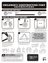
4. Basic Design
4.1 Disconnecetor
Figure 3 and Table 1 contain the most important components of the type SGF two-column rotary
disconnector.
Figure 3 : Basic design of type SGF two-column rotary disconnector
Table 1 : Basic design of type SGF two-column rotary disconnector
Designation Item No. Remarks
Disconnector base 2 Consisting of : Sectional steel base frame
(221),rotary pedestals (70),diagonal rod(68)
Rotary pedestals 70 Enclosed, maintenance-free, on stud bolt for
adjustment
Support insulator 201 —
Rotary heads 284 Enclosed, maintenance-free, swivelling
0
range 360
Current paths 5, 6 Welded aluminium construction, corrosion-
resistant
Contact finger 66 Cu-Cr-Zr alloy, silver-faced
Contact pieces 67 Cu, silver-faced
High-voltage terminals 17 Flat terminal to DIN 46 203 with :
- 4 bore holes : For rated currents < 1 600 A
- 8 bore holes : For rated currents > 1 600 A
and NEMA
Operating mechanism 75 Optionally : Motor-operated or manual
4/113
1HDB 050016-YN-A

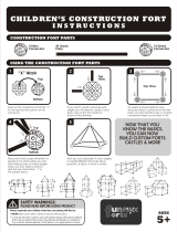
4.2 Earthing - Switch
Figure 4 and Table 2 contain the most important components of the earthing switch.
Figure 4 : Basic design of earthing switch
Table 2 : Basic design of earthing switch
Designation Item No. Remarks
Earthing connection 79 Cu, flexible
Earthing-switch shaft 337 Steel tube, hot-dip galvanized
Tubular contact arm 23 Aluminium
Contact finger 20 Cu-Cr-Zr alloy, silver-faced
Earthing contact 18 Cu, silver-faced
Operating mechanism 77 Optionally : Motor-operated or manual
5/113
1HDB 050016-YN-A

5. Mode of Operation
5.1 General
The type SGF two-column rotary disconnector has separate operating mechanisms for the
disconnector and the earthing switch.
Prevention of automatic operating or closing
When the equipments switched on or off, a dead-center position is passed through just before the end
positions are reached. This prevents the automatic opening or closing of the disconnector or earthing
switch as a result of :
l Short-circuit
l External influence : (e.g. storm or earthquake)
5.2 Disconnector
Operating mechanism :-
The operating mechanism (75) of the disconnector transfers the operating energy via the operating rod
(37) to the rotary pedestal (70). The diagonal rod (68) connects the two rotary pedestals of each pole.
Consequently, both pole halves are moved simultaneously.
The support insulators (201) transfer the torque to the two current-path halves (5, contact side) and (6,
0
finger side). These pass through an angle of rotation of 90 during switching.
Current transfer :-
During switching-on, the counter-contact (67) glides between the contact fingers (66). This establishes
the connection between the two current-path halves. The current is transferred via tulip-type contacts
in the rotary heads (284) to the high-voltage terminals (17).
Mechanical coupling inside a disconnector group :-
Via the coupling rods (15), the movement of the operated pole is transferred simultaneously to the other
poles of a disconnector group.
Figure 5 : Mode of operation of type SGF two-column rotary disconnector
(example : 3-pole in parallel arrangement)
6/113
1HDB 050016-YN-A

5.3 Earthing Switch
Operating mechanism :-
The operating mechanism (77) of the earthing switch transfers the operating energy via the operating
rod (71) to the earthing-switch shaft (337). The tubular contact arm (23) swivels up (ON) or down
(OFF). During switching-on, the contact fingers (20) glide over the earthing contact (18). In the ON end
position, they are in preloaded contact against the stop.
Earthing connection :-
The earthing connection (79) connects the tubular contact are (23) to the earthed sectional-steel base
frame (221) of the disconnector.
5.4 Interlocking
The disconnector and the earthing switch can be interlocked according to the following principle :
• Disconnector only ON when earthing switch OFF
• Earthing switch only ON when disconnector OFF
Interlocking is mechanical and/or electrical, depending on the version
Note : Mechanical interlocks between disconnector and earthing switch are fitted at the factory.
Retrofitting is not possible.
Figure 6 : Mode of operation of earthing switch (example : 3-pole in parallel arrangement)
7/113
1HDB 050016-YN-A

Table 3 : General electrical data of type SGF two-column rotary disconnector (standard values)
Rated voltage kV 36 72.5 123 145 170 245 300 362
Rated normal current A 1600 1600 1600 1600 1600 1600 1600 1600
2500 2500 2500 2500 2500 2500 2500 2500
3150 3150 3150 3150 3150 3150 3150 3150
Rated peak - withstand current A 100 100 100 100 100 100/125 100/125 100/125
Rated short time current (1 sec) kA 40 40 40 40 40 40/50 40/50 40/50
Rated Power frequency withstand
voltage (50Hz, 1min)
- against earth & between poles kVp 70 140 230 275 325 460 380 450
- over isolating distance kVp 80 160 265 315 375 530 435 520
Rated Lightening-impulse withstand
voltage 1.2/50ms
- against earth and between poles kVp 170 325 550 650 750 1050 1050 1175
- over isolating distance kVp 195 375 650 750 860 1200
1050 (+170) 1175 (+205)
Rated Switching-impulse withstand
voltage 1.2/50ms
- against earth and between poles kVp - - - - - - 850 950
- over isolating distance kVp - - - - - -
700 (+245) 800 (+295)
Discharge-inception voltage kV >27 >46 >80 >95 >110 >160 >191 >230
Radio-interference voltage kV <500 <500 <500 <500 <1000 <1000 <1000 <2500
(at 23 kV) (at 46 kV) (at 78 kV) (at 92 kV) (at 108 kV) (at 156 kV) (at 191 kV) (at 230 kV)
3-phase switching capacity A 2 2 2 2 2 1.5 1 1
inductive, capacitive
6. Technical Data
6.1 General Electrical Data
Note : The precise electrical data is contained in the data sheets supplied. The data in Table 3 contains
of standard values.
6.2 General Mechanical Data
Note : The precise mechanical data are contained in the data sheets supplied. The data in Table 4
contains of standard values.
Table 4 : General mechanical data of type SGF two-column rotary disconnector (standard values)
Minimum breaking load of support N 4000 6000 8000 100000
instructors
Permissible mechanical terminal load
- Static and dynamic N 3000 4500 6000 6000
- Static portion N 1200 1500 1500 1500
8/113
1HDB 050016-YN-A

6.3 General Main Dimensions
Note : The precise dimensions are contained in the dimensions drawings supplied. The dimensions in
Table 5 are standard values.
9/113
Figure 7 : General main dimension of SFG two-column rotary disconnector
Table 5 : General main dimensions of type SGF two-column rotary disconnector (standard values)
Rated voltage kV 36 72.5 123 145 170 245 300 362
Rated normal current A 1600 1600 1600 1600 1600 1600 1600 1600
2500 2500 2500 2500 2500 2500 2500 2500
3150 3150 3150 3150 3150 3150 3150 3150
A Support-insulator distance mm 1000 1000 1400 1650 1830 2620 2620 3200
B Base-frame Length mm 1300 1300 1700 1950 2130 2920 2920 3500
C Disconnector Height
for 1650 A mm 1093 1325 1775 2055 2255 2855 3205 3255
for 2500 A mm 1143 1375 1825 2105 2305 2905 3255 3255
for 3150 A mm 1193 1425 1875 2155 2355 2955 3305 3305
D Insulator Height mm 508 770 1220 1500 1700 2300 2650 2650
E Disconnector width (open) mm 560 560 760 925 1030 1370 1370 1725
F Isolating distance mm 800 800 1200 1450 1630 2420 2300 2700
G Length of mounting of Earthing
switch mm 450 450 450 450 450 450 450 450
1HDB 050016-YN-A

6.4 Minimum Distance between Disconnector Poles
Note : The precise dimensions are contained in the dimension drawing supplied. The dimensions in
Table 6 are standard values.
Table 6 : Minimum distances P
min between poles of disconnector in series and parallel arrangement
(standard values)
Rated voltage kV 123 145 170 245 300
Parallel arrangement mm 1 970 2 330 2 640 3 570 4 000
+ Series arrangement mm 2 700 3 150 3 530 4 920 5 700
Table 8 : Minimum distances Pmin between poles of disconnector in parallel arrangement
Figure 9 : Minimum distances Pmin between poles of disconnector in series arrangement
10/113
1HDB 050016-YN-A

7. Scope of Supply
Note : The disconnector is supplied in components
7.1 Disconnector
The scope of supply does not include the fixing materials for mounting the disconnector on the
supporting structures.
The components supplied comprises :
l Disconnector base (2) consisting of : Sectional-steel base frame (221), rotary pedestals (70),
diagonal rod (68), disconnector operating lever (69), connecting lever (3) and transportation
angle (328) Figure 13
l Support insulators (201)
l Current-path half, contact side (5)
l Current-path half, finger side (6)
l Operating mechanism for disconnector (75)
l Operating rod (37)
l Operating lever (74) with clamping cover (334)
l Coupling rods (15)
l If operating mechanism mounted separately : Vertical operating shaft (43) and pivot bearing (42)
Figure 21
l If operating mechanism with lateral offset : Operating rod (83) Figure 25
l Small parts
A
A
A
Figure 10 : Scope of supply, disconnector
11/113
1HDB 050016-YN-A

7.2 Earthing Switch
The supply of the earthing switch comprises.
l Earthing-switch links (336)
l Tubular contact arms (23) wiwth contact finger (20) and T-type clamp(329)
l Earthing contact (18)
l Operating mechanism for earthing switch (77)
l Operating rod (37)
l Operating lever (76) with clamping cover (334)
l Earthing connections (79)
l For 2nd earthing switch : earthing connections (343)
l Earthing - switch shaft (337)
l In case of series arrangement : Earthing-switch shafts (73) with welded earthing - switch lever
(339) Figure 53
l Earthing-switch lever (19)
l In case of series arrangement : Coupling rods (15) Figure 55
l If operating mechanism mounted separately : Vertical operating shaft (43) and pivot bearing
(42) Figure 38
l If operating mechanism with lateral offset : Operating rod (83) and offset bearing (376) Figure
42
l Small parts
A
A
A
A
Figure 11 : Scope of supply, earthing switch
12/113
1HDB 050016-YN-A

8 Shipping and Storage
8.1 Shipping
The equipment is shipped on pallets (Germany) or in boxes (outside Germany)
Note : After unpacking, check all supplied equipment immediately for shipping damage. Report
shipping damage without delay to the forwarding agency.
8.2 Storage
Caution : In the case of inappropriate storage of the individual components, there is the risk of ingress
of water. For this reason, disconnector parts and operating mechanisms must always be stored in the
mounting position.
It is advisable to leave all assemblies in the shipping packing until the start of mounting in order to
protect against contamination and damage.
Special Note : Operating mechanisms are supplied in special packing. This protects the operating
mechanisms against corrosion within a limited time and in a dry atmosphere. It is advisable not to open
this packing until just before the start of mounting.
Caution : In the case of lengthy storage and/or a damp atmosphere , there may be undesired formation
of condensation in the operating mechanisms. If the shipping time and storage time together amount to
more than 6 months or if operating mechanisms are stored in a damp atmosphere, the special packing
must be removed immediately and the electrical heating of the operating mechanisms must be started.
Before doing this, remove bags with desiccative from the operating mechanisms !
13/113
1HDB 050016-YN-A
/