Miller KD536837 Owner's manual
- Category
- Welding System
- Type
- Owner's manual
This manual is also suitable for

cover 7/93* − ST-134 686-C PRINTED IN USA
© 1994 MILLER Electric Mfg. Co.
Read and follow these instructions and all
safety blocks carefully.
Have only trained and qualified persons
install, operate, or service this unit.
Call your distributor if you do not understand
the directions.
Give this manual to the operator.
For help, call your distributor
or: MILLER Electric Mfg. Co., P.O. Box 1079,
Appleton, WI 54912 414-734-9821
OWNER’S
MANUAL
January 1994 Form: OM-481B
Effective With Serial No. KD536837
CC/CV, DC Welding Generator
For SMAW, GMAW, FCAW, SAW Welding And CAC-A
600 Amps, 44 VDC At 100% Duty Cycle
Deutz F4L912 Air-Cooled, Diesel Engine
3kVA/kW AC Auxiliary Power With Overload Protection
Automatic Shutdown For Low Oil Pressure, High Oil Temperature, Or
Cooling System Failure
Big Blue® 600D


OM-481B − 1/94
EMF INFORMATION
The following is a quotation from the General Conclusions Section of
the U.S. Congress, Office of Technology Assessment, Biological
Effects of Power Frequency Electric & Magnetic Fields −
Background Paper, OTA-BP-E-53 (Washington, DC: U.S.
Government Printing Office, May 1989): “. . . there is now a very large
volume of scientific findings based on experiments at the cellular
level and from studies with animals and people which clearly
establish that low frequency magnetic fields can interact with, and
produce changes in, biological systems. While most of this work is
of very high quality, the results are complex. Current scientific
understanding does not yet allow us to interpret the evidence in a
single coherent framework. Even more frustrating, it does not yet
allow us to draw definite conclusions about questions of possible risk
or to offer clear science-based advice on strategies to minimize or
avoid potential risks.”
To reduce magnetic fields in the workplace, use the following
procedures:
1. Keep cables close together by twisting or taping them.
2. Arrange cables to one side and away from the operator.
3. Do not coil or drape cables around the body.
4. Keep welding power source and cables as far away as practical.
5. Connect work clamp to workpiece as close to the weld as
possible.
About Pacemakers:
The above procedures are among those also normally
recommended for pacemaker wearers. Consult your doctor for
complete information.
Considerations About Welding And The Effects Of Low Frequency Electric And
Magnetic Fields
NOTE
mod10.1 4/93
TABLE OF CONTENTS
SECTION 1 − SAFETY INFORMATION 1. . . . . . . . . . . . . . . . . . . . . . . . . . . . . . . . . . . . . . . . . . . . . . . . . . . .
SECTION 2 − SPECIFICATIONS
2-1. Volt-Ampere Curves 2. . . . . . . . . . . . . . . . . . . . . . . . . . . . . . . . . . . . . . . . . . . . . . . . . . . . . . . . . . . .
2-2. Duty Cycle 2. . . . . . . . . . . . . . . . . . . . . . . . . . . . . . . . . . . . . . . . . . . . . . . . . . . . . . . . . . . . . . . . . . . .
2-3. Fuel Consumption 3. . . . . . . . . . . . . . . . . . . . . . . . . . . . . . . . . . . . . . . . . . . . . . . . . . . . . . . . . . . . .
2-4. AC Auxiliary Power 3. . . . . . . . . . . . . . . . . . . . . . . . . . . . . . . . . . . . . . . . . . . . . . . . . . . . . . . . . . . .
SECTION 3 − INSTALLATION
3-1. Selecting A Location And Moving Welding Generator 4. . . . . . . . . . . . . . . . . . . . . . . . . . . . . . .
3-2. Installing Exhaust Pipe And Rain Cap 5. . . . . . . . . . . . . . . . . . . . . . . . . . . . . . . . . . . . . . . . . . . .
3-3. Connecting The Battery 6. . . . . . . . . . . . . . . . . . . . . . . . . . . . . . . . . . . . . . . . . . . . . . . . . . . . . . . . .
3-4. Lower Front Panel 6. . . . . . . . . . . . . . . . . . . . . . . . . . . . . . . . . . . . . . . . . . . . . . . . . . . . . . . . . . . . .
3-5. Grounding The Generator Auxiliary Power System 7. . . . . . . . . . . . . . . . . . . . . . . . . . . . . . . . .
3-6. Engine Prestart Checks 7. . . . . . . . . . . . . . . . . . . . . . . . . . . . . . . . . . . . . . . . . . . . . . . . . . . . . . . . .
3-7. Selecting And Preparing Weld Output Cables 8. . . . . . . . . . . . . . . . . . . . . . . . . . . . . . . . . . . . . .
3-8. Connecting To Weld Output Terminals 9. . . . . . . . . . . . . . . . . . . . . . . . . . . . . . . . . . . . . . . . . . . .
3-9. Remote 14 Receptacle Or Terminal Strip Information And Connections 9. . . . . . . . . . . . . . . .
3-10. Installing Optional Ether Cylinder 11. . . . . . . . . . . . . . . . . . . . . . . . . . . . . . . . . . . . . . . . . . . . . . . . .
SECTION 4 − OPERATING THE WELDING GENERATOR 12. . . . . . . . . . . . . . . . . . . . . . . . . . . . . . . . . . .
SECTION 5 − OPERATING AUXILIARY EQUIPMENT
5-1. 120 Volt Duplex Receptacles 18. . . . . . . . . . . . . . . . . . . . . . . . . . . . . . . . . . . . . . . . . . . . . . . . . . . .
5-2. Optional 240 Volt Duplex Receptacle 19. . . . . . . . . . . . . . . . . . . . . . . . . . . . . . . . . . . . . . . . . . . . .
SECTION 6 − MAINTENANCE & TROUBLESHOOTING
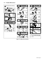
6-1. Routine Maintenance 21. . . . . . . . . . . . . . . . . . . . . . . . . . . . . . . . . . . . . . . . . . . . . . . . . . . . . . . . . . .
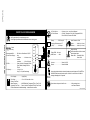
6-2. Maintenance Lights 23. . . . . . . . . . . . . . . . . . . . . . . . . . . . . . . . . . . . . . . . . . . . . . . . . . . . . . . . . . . .
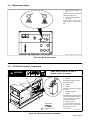
6-3. Oil And Fuel System Components 23. . . . . . . . . . . . . . . . . . . . . . . . . . . . . . . . . . . . . . . . . . . . . . .
6-4. Servicing Air Cleaner 24. . . . . . . . . . . . . . . . . . . . . . . . . . . . . . . . . . . . . . . . . . . . . . . . . . . . . . . . . . .
6-5. Adjusting Engine Speed 25. . . . . . . . . . . . . . . . . . . . . . . . . . . . . . . . . . . . . . . . . . . . . . . . . . . . . . . .
6-6. Checking Battery Voltage Or Replacing Battery 25. . . . . . . . . . . . . . . . . . . . . . . . . . . . . . . . . . . .
6-7. Overload Protection 26. . . . . . . . . . . . . . . . . . . . . . . . . . . . . . . . . . . . . . . . . . . . . . . . . . . . . . . . . . . .
6-8. Checking And Replacing Alternator Belt 27. . . . . . . . . . . . . . . . . . . . . . . . . . . . . . . . . . . . . . . . . . .
6-9. Optional Ether Starting Aid Maintenance 28. . . . . . . . . . . . . . . . . . . . . . . . . . . . . . . . . . . . . . . . . .
6-10. Optional Spark Arrestor Inspection And Cleaning 28. . . . . . . . . . . . . . . . . . . . . . . . . . . . . . . . . . .
6-11. Optional Overspeed Shutdown Valve Adjustment 29. . . . . . . . . . . . . . . . . . . . . . . . . . . . . . . . . .
6-12. Troubleshooting 30. . . . . . . . . . . . . . . . . . . . . . . . . . . . . . . . . . . . . . . . . . . . . . . . . . . . . . . . . . . . . . .

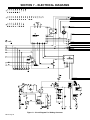
SECTION 7 − ELECTRICAL DIAGRAMS 32. . . . . . . . . . . . . . . . . . . . . . . . . . . . . . . . . . . . . . . . . . . . . . . . . . .
SECTION 8 − RUN-IN PROCEDURE
8-1. Run-In Procedure Using Load Bank 37. . . . . . . . . . . . . . . . . . . . . . . . . . . . . . . . . . . . . . . . . . . . . .
8-2. Run-In Procedure Using Resistance Grid 37. . . . . . . . . . . . . . . . . . . . . . . . . . . . . . . . . . . . . . . . .
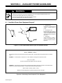
SECTION 9 − AUXILIARY POWER GUIDELINES
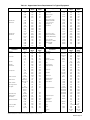
9-1. How Much Power Does Equipment Require? 38. . . . . . . . . . . . . . . . . . . . . . . . . . . . . . . . . . . . . .
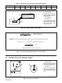
9-2. How Much Power Can Generator Supply? 40. . . . . . . . . . . . . . . . . . . . . . . . . . . . . . . . . . . . . . . .
9-3. Typical Connections To Supply Standby Power 41. . . . . . . . . . . . . . . . . . . . . . . . . . . . . . . . . . . .
9-4. Selecting Extension Cord 42. . . . . . . . . . . . . . . . . . . . . . . . . . . . . . . . . . . . . . . . . . . . . . . . . . . . . . .
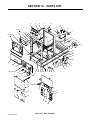
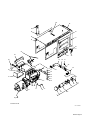
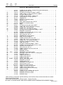
SECTION 10 − PARTS LIST
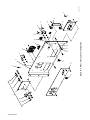
Figure 10-1. Main Assembly 44. . . . . . . . . . . . . . . . . . . . . . . . . . . . . . . . . . . . . . . . . . . . . . . . . . . . . . . . . . .
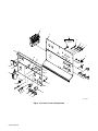
Figure 10-2. Panel, Front w/Components 48. . . . . . . . . . . . . . . . . . . . . . . . . . . . . . . . . . . . . . . . . . . . . . . .
Figure 10-3. Panel, Front Lower w/Components 50. . . . . . . . . . . . . . . . . . . . . . . . . . . . . . . . . . . . . . . . . .
Figure 10-4. Control Box 52. . . . . . . . . . . . . . . . . . . . . . . . . . . . . . . . . . . . . . . . . . . . . . . . . . . . . . . . . . . . . .
Figure 10-5. Generator 53. . . . . . . . . . . . . . . . . . . . . . . . . . . . . . . . . . . . . . . . . . . . . . . . . . . . . . . . . . . . . . . .
Optional Equipment 54. . . . . . . . . . . . . . . . . . . . . . . . . . . . . . . . . . . . . . . . . . . . . . . . . . . . . . . . . . . . . . . . . .

OM-481 Page 1
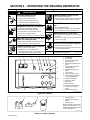
SECTION 1 − SAFETY INFORMATION
mod1.1 2/93
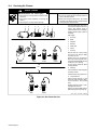
Read all safety messages throughout this manual.
Obey all safety messages to avoid injury.
Learn the meaning of WARNING and CAUTION.
1 Safety Alert Symbol
2 Signal Word
WARNING means possible death
or serious injury can happen.
CAUTION means possible minor
injury or equipment damage can
happen.
3 Statement Of Hazard And Re-
sult
4 Safety Instructions To Avoid
Hazard
5 Hazard Symbol (If Available)
6 Safety Banner
Read safety blocks for each sym-
bol shown.
7 NOTE
Special instructions for best oper-
ation − not related to safety.
2
NOTE
ELECTRIC SHOCK can kill.
• Do not touch live electrical parts.
• Disconnect input power before
installing or servicing.
WARNING
READ SAFETY BLOCKS at start of
Section 3-1 before proceeding.
WARNING
5
4
6
7
1 2
CAUTION
MOVING PARTS can injure.
• Keep away from moving parts.
• Keep all panels and covers closed
when operating.
3
Turn Off switch when using high frequency.
Figure 1-1. Safety Information
SECTION 2 − SPECIFICATIONS
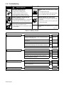
Table 2-1. Welding Generator
Specification Description
Type Of Output Constant Current/Constant Voltage (CC/CV), Direct Current (DC)
Rated Weld Output 600 Amperes, 44 Volts DC At 100% Duty Cycle (See Section 2-2)
Amperage Range 45-800 A
Max. Open-Circuit Voltage 95 Volts DC
Welding Process Shielded Metal Arc (SMAW), Gas Metal Arc (GMAW), Flux Cored Arc (FCAW), And Submerged Arc
Welding (SAW); Air Carbon Arc Cutting and Gouging (CAC-A)
Auxiliary Power Rating Single-Phase, 3 kVA/kW, 120/240 Volts AC, 26 Amperes, 60 Hz
Engine Deutz F4L912 Air-Cooled, Diesel Engine
Engine Speed (No Load) Weld/Power Speed: 1850 rpm
Fuel Tank Capacity 19 gal (72 L)
Overall Dimensions See Figure 3-2
Weight Net: 2250 lb (1021 kg); Ship: 2380 lb (1080 kg)
Options See Rear Cover

OM-481 Page 2
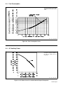
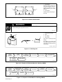
2-1. Volt-Ampere Curves
The volt-ampere curves show the
minimum and maximum voltage
and amperage output capabilities of
the welding generator. Curves of
other settings fall between the
curves shown.
rsb1.1 10/91 − SB-133 004 / SB-133 003
A. For Constant Current (CC) Mode B. For Constant Voltage (CV) Mode
Figure 2-1. Volt-Ampere Curves
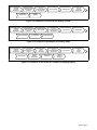
2-2. Duty Cycle
CAUTION
WELDING LONGER THAN RATED DUTY CYCLE can damage unit and void warranty.
• Do not weld at rated load longer than shown below.
warn7.1 8/93
Duty Cycle is percentage of 10
minutes that unit can weld at
rated load without overheating.
Continuous Welding
sb1.1 8/93 − SB-134 397-A
0
10
Minutes
100% Duty Cycle At 600 Amperes
Definition
Chart
Figure 2-2. Duty Cycle

OM-481 Page 3
2-3. Fuel Consumption
The fuel consumption curve shows
typical fuel use under weld or power
loads.
rsb2.1 10/91 − SB-133 838
Figure 2-3. Fuel Consumption Curve
2-4. AC Auxiliary Power
The ac power curve shows the auxil-
iary power in amperes available at
the 120 and optional 240 volt
receptacles.
rsb3.1* 2/92 − SB-109 365-B
Figure 2-4. AC Power Curve For 120 And 240 Volt Duplex Receptacles

OM-481 Page 4
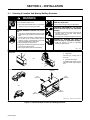
SECTION 3 − INSTALLATION
3-1. Selecting A Location And Moving Welding Generator
WARNING
ENGINE EXHAUST GASES can kill.
• Do not breathe exhaust fumes.
• Use in open, well-ventilated areas, or vent exhaust
outside and away from building air intakes.
ENGINE EXHAUST SPARKS can cause
fire.
• Use only U.S. Forestry Department approved spark
arrestor and comply with all local, state, and federal
laws.
• A spark arrestor is mandatory in all National Forests
and in grass, brush, or forest covered lands in
California, Oregon, and Washington. Check with
state and local authorities in other areas.
• Properly maintain the spark arrestor.
• Stop engine and allow exhaust system to cool down
before servicing spark arrestor.
• Service spark arrestor away from flammables.
HOT ENGINE EXHAUST AND EXHAUST
PIPE can cause fires.
• Keep exhaust and pipe away from flammables.
FALLING EQUIPMENT can cause
serious personal injury and equipment
damage.
• Use lifting eye to lift unit only, NOT running gear, gas
cylinders, trailer, or any other heavy options,
accessories, or devices.
• Use equipment of adequate capacity to lift the unit.
TILTING OF TRAILER can result in
personal injury or equipment damage.
• Install unit properly on trailer (if applicable)
according to trailer manual.
rwarn1.1 3/93
rsb20.2* 11/93 − ST-800 477 / ST-134 686-C
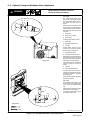
1 Lifting Eye
2 Lifting Forks
Use lifting eye or lifting forks to
move unit.
3 Cross Member Support
If using lifting forks, lift only from end
with cross member support (engine
end).
Location
OR
OR
1
Movement
2
3
18 in
(460 mm)
18 in
(460 mm)
18 in
(460 mm)
18 in
(460 mm)
18 in
(460 mm)
Figure 3-1. Movement And Location Of Welding Generator

OM-481 Page 5
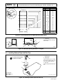
Overall dimensions (A, B, and C) include lifting eye, handles, hardware, etc.
NOTE
ST-156 466
B
A
C
Inches Millimeters
A 58 1473
B 32 813
C 68 1727
D 68 1727
E 62-3/8 1584
F 50-1/2 1283
G 46-1/2 1181
H 36 914
J 28-3/16 716
K 13-3/4 349
L 9-3/4 248
M 6-1/8 156
N 29-7/8 759
P 32 813
Q 1-1/16 27
R 21/32 Dia. 16.7 Dia.
16 Holes 16 Holes
D
E
F
G
H
J
K
L
M
N
P
Q
R
Engine End
Figure 3-2. Overall Dimensions And Base Mounting Hole Layout
1 Trailer Hitch
Install unit onto trailer according to
trailer manual.
S-0024-B
1
20°
20°
15°
Engine
End
17.5°
Figure 3-3. Maximum Welding Generator Tilt Angles
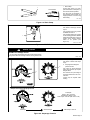
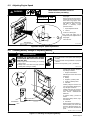
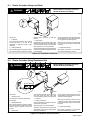
3-2. Installing Exhaust Pipe And Rain Cap
rsb19.4* 5/92 − ST-154 087
Stop engine and allow to cool.
1 Exhaust Pipe
2 Muffler Pipe
Install exhaust pipe over muffler
pipe. Secure exhaust pipe to top
cover using supplied hardware.
3 Rain Cap
Install so cap opens toward front of
unit.
1/2 in
Tools Needed:
1
2
3
Do not blow exhaust toward
air cleaner or air intake.
Figure 3-4. Installing Exhaust Pipe And Rain Cap

OM-481 Page 6
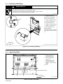
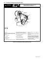
3-3. Connecting The Battery
WARNING
SPARKS can cause BATTERY GASES TO EXPLODE; BATTERY ACID can burn eyes and skin.
• Stop engine before disconnecting or connecting battery cables.
• Always wear a face shield and proper protective clothing when working on a battery.
• Do not allow tools to cause sparks when working on a battery.
rwarn2.1 9/91
ST-153 654-A / Ref. ST-131 784-A / Ref. S-0756
1 Engine Control Switch
Place switch in the Off position.
Remove rear left side panel.
2 Positive (+) Battery Terminal
3 Positive (+) Battery Cable
Connect positive cable first.
4 Negative (−) Battery Terminal
5 Negative (−) Battery Cable
Connect negative cable last.
Reinstall side panel.
If engine does not crank, check bat-
tery voltage according to Section
6-6.
Tools Needed:
1/2 in
1
4
2
+
−
3
5
Figure 3-5. Connecting The Battery
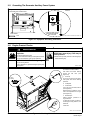
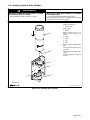
3-4. Lower Front Panel
Ref. ST-134 687-A
Open lower front door.
1 Equipment Grounding
Terminal (Section 3-5)
2 Remote 14 Receptacle
(Section 3-9)
3 Positive (+) Weld Output
Terminals (Section 3-8)
4 Negative (−) Weld Output Ter-
minals
Close door.
Tools Needed:
3/8, 1/2 in
1
2
34
Route all cables under bar.
Figure 3-6. Lower Front Panel

OM-481 Page 7
3-5. Grounding The Generator Auxiliary Power System
GND/PE
rsb5.1 8/93 − Ref. ST-134 687-A / S-027 657-D
1 Equipment Grounding
Terminal
1
Tools Needed:
1/2 in
Connect To Earth Ground
If Required By National
Or Local Codes
The generator auxiliary power neutral
is connected to the machine frame.
Figure 3-7. Equipment Grounding Connection
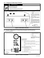
3-6. Engine Prestart Checks
WARNING
ENGINE FUEL can cause fire or
explosion.
• Stop engine before fueling.
• Do not fuel while smoking or near sparks or flames.
• Do not overfill tank; clean up any spilled fuel.
USE OF GASOLINE will damage engine.
• Do not use gasoline.
Lack of lubrication in gasoline damages injector pump
and injectors.
REMOVE FUEL CAP SLOWLY; FUEL
SPRAY may cause injury; FUEL may be
under pressure.
• Rotate fuel cap slowly and wait until hissing stops
before removing cap.
rwarn3.1* 3/93
rsb4.2 11/92 − ST-156 467-B
Check all fluids daily. Engine must
be cold and on a level surface.
Add fresh fuel before starting
engine the first time (see
Figure 6-2).
1 Fuel Cap
Do not run out of fuel or air enters
fuel system and causes starting
problems.
2 Oil Dipstick
3 Oil Fill Tube
If oil is not up to full mark, add oil
(see Figure 6-2).
Engine stops if oil pressure is too
low or oil temperature is too high
(see Figure 4-9).
4 Exhaust Pipe
Follow break-in procedure in
engine manual.
If unburned fuel and oil collect in
exhaust pipe during break-in, see
Section 8.
Close door
1
FUEL
OIL
2
3
Full
1/2 in
(13 mm) Full
4
Figure 3-8. Checking Oil And Fuel

OM-481 Page 8
3-7. Selecting And Preparing Weld Output Cables
sb6.5* 11/92 − S-0752
1 Weld Output Cable
Determine total cable length in weld
circuit and maximum welding am-
peres. Use Table 3-1 to select prop-
er cable size.
Use shortest cables possible.
Do not use damaged cables.
2 Terminal Lug
Use lugs of proper amperage
capacity and hole size for connect-
ing to work clamp, wire feeder or
electrode holder, and weld output
terminals.
3 Wire Feeder
4 Insulated Electrode Holder
5 Work Clamp
Install onto work cable.
Tools Needed:
10 ft (3 m)
1
Total Cable
Length In Weld
Circuit = 20 ft (6 m)
10 ft (3 m)
For Example,
2
5
3
2
4
OR
Figure 3-9. Selecting And Preparing Weld Output Cables
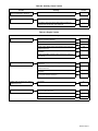
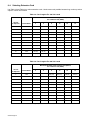
Table 3-1. Weld Cable Size*
Total Cable (Copper) Length In Weld Circuit Not Exceeding
100 ft (30 m) Or Less
150 ft
(45 m)
200 ft
(60 m)
250 ft
(70 m)
300 ft
(90 m)
350 ft
(105 m)
400 ft
(120 m)
Welding
Amperes
10 To 60%
Duty Cycle
60 Thru 100%
Duty Cycle
10 Thru 100% Duty Cycle
100 4 4 4 3 2 1 1/0 1/0
150 3 3 2 1 1/0 2/0 3/0 3/0
200 3 2 1 1/0 2/0 3/0 4/0 4/0
250 2 1 1/0 2/0 3/0 4/0 2-2/0 2-2/0
300 1 1/0 2/0 3/0 4/0 2-2/0 2-3/0 2-3/0
350 1/0 2/0 3/0 4/0 2-2/0 2-3/0 2-3/0 2-4/0
400 1/0 2/0 3/0 4/0 2-2/0 2-3/0 2-4/0 2-4/0
500 2/0 3/0 4/0 2-2/0 2-3/0 2-4/0 3-3/0 3-3/0
600 3/0 4/0 2-2/0 2-3/0 2-4/0 3-3/0 3-4/0 3-4/0
700 4/0 2-2/0 2-3/0 2-4/0 3-3/0 3-4/0 3-4/0 4-4/0
800 4/0 2-2/0 2-3/0 2-4/0 3-4/0 3-4/0 4-4/0 4-4/0
900 2-2/0 2-3/0 2-4/0 3-3/0 3-4/0 4-4/0 4-4/0
1000 2-2/0 2-3/0 2-4/0 3-3/0 4-3/0 4-4/0
*Weld cable size (AWG) is based on either a 4 volts or less drop or a current density of at least 300 circular mils per ampere. Ref. S-0007-C

OM-481 Page 9
3-8. Connecting To Weld Output Terminals
WARNING
ELECTRIC SHOCK can kill.
• Always wear dry insulating gloves.
• Do not touch live electrical parts.
• Stop engine before making any weld output connections.
• Read Safety Precautions at beginning of this manual.
rwarn13.1 2/92
Ref. ST-134 687-A / ST-145 043
1 Positive (+) Weld Output
Terminals
2 Negative (−) Weld Output Ter-
minals
For Direct Current Electrode Posi-
tive (DCEP), connect work cable to
− terminal and electrode holder
cable to + terminal.
For Direct Current Electrode Nega-
tive (DCEN), reverse cable con-
nections.
To prevent overheating and dam-
age, two terminals are provided for
each polarity in case more than one
cable is needed to carry current to
a single arc (see Table 3-1). This
unit is not designed to supply multi-
ple arcs.
Tools Needed:
3/8, 7/8 in
12
Figure 3-10. Weld Output Connections
3-9. Remote 14 Receptacle Or Terminal Strip Information And Connections
A. Remote 14 Receptacle
sb7.1 3/93 − Ref. ST-145 043 / Ref. S-0004-A / S-0750
1 Remote 14 Receptacle RC3
2 Keyway
3 Plug
4 Threaded Collar
To connect to this receptacle, align
keyway, insert plug, and tighten
threaded collar.
AJ
B
K
I
C
L
NH
D
M
G
E
F
1 2
34
Socket Information:
Remote Contactor
A 24 volts ac. Protected by circuit breaker CB4.
B Contact closure to pin A completes 24 volts ac contactor control
circuit.
I 115 volts ac. Protected by circuit breaker CB3.
J Contact closure to pin I completes 115 volts ac contactor control
circuit.
G Circuit common for 24 and 115 volts ac circuits.
Remote Amperage/Voltage Control
C Command reference; +10 volts dc.
D Control circuit common.
E Input command signal (potentiometer wiper or 0 to +10 volts dc).
K Chassis common.
The remaining sockets are not used.
3/8 in
Tools Needed:
Figure 3-11. Remote 14 Connections

OM-481 Page 10
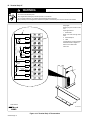
B. Terminal Strip 3T
WARNING
ELECTRIC SHOCK can kill; UNEXPECTED OUTPUT can cause serious injury.
• Do not touch live electrical parts.
• Stop engine before making any internal inspection or connections.
• Do not connect to Remote 14 receptacle and terminal strip at the same time.
Output (Contactor) can be energized from either the receptacle or terminal strip. Use only one remote control method.
ST-134 839-A
Stop engine.
Remove plug from remote control
cord.
Open right side door.
1 Strain Relief
Route cord leads through strain
relief.
2 Terminal Strip 3T
3 Label
Connect leads to 3T using terminal
information shown in Figure 3-11.
Secure cord in strain relief.
Close door.
15A
0-10VDC
0-1 k
Circuit Common
Equipment
S-138 042
24VAC
A
B
C
D
E
G
I
K
J
Contactor
Output
Ground
Feeder
115VAC
Contactor
24VAC 10A Feeder Power
3T
Power
115VAC
Remote
A/V
Ω
2
Tools Needed:
1
3
Figure 3-12. Terminal Strip 3T Connections

OM-481 Page 11
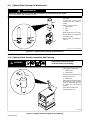
3-10. Installing Optional Ether Cylinder
WARNING
IMPROPER HANDLING OR EXPOSURE TO ETHER
can seriously harm your health.
• Follow manufacturer’s safety instructions on cylinder.
INJECTING ETHER WHILE ENGINE IS RUNNING
can damage engine.
• Do not use Ether Starting Aid while engine is running.
After installing cylinder, wait at least 10 minutes before use to let ether
particles settle to prevent atomizer plugging.
rsb15.1 6/92A − ST-153 382
Stop engine. Open side door(s) to
locate ether starting aid.
1 Ether Cylinder
Obtain cylinder.
2 Nozzle
Remove protective cover, and
clean nozzle and fitting area on
cylinder.
3 Clamp
4 Fitting
5 Cap
6 Valve
Remove valve cap, and clean fitting
area.
Insert cylinder through clamp and
onto fitting.
Tighten clamp when cylinder is tight
in fitting.
Put cap on fitting when cylinder is
removed.
1
2
3
4
6
5
Tools Needed:
Figure 3-13. Installing Ether Cylinder

OM-481 Page 12
SECTION 4 − OPERATING THE WELDING GENERATOR
ELECTRIC SHOCK can kill.
• Do not touch live electrical parts.
• Always wear dry insulating gloves.
• Insulate yourself from work and ground.
• Stop engine before installing or servicing.
• Keep all panels and covers securely in place.
WELDING can cause fire or explosion.
• Do not weld near flammable material.
• Watch for fire; keep extinguisher nearby.
• Do not locate unit over combustible surfaces.
• Do not weld on closed containers.
• Allow work and equipment to cool before handling.
ARC RAYS can burn eyes and skin;
NOISE can damage hearing.
• Wear welding helmet with correct shade of filter.
• Wear correct eye, ear, and body protection.
FUMES AND GASES can be hazardous.
• Keep your head out of the fumes.
• Ventilate area, or use breathing device.
• Read Material Safety Data Sheets (MSDSs) and
manufacturer’s instructions for material used.
ENGINE EXHAUST GASES can kill.
• Do not breathe exhaust fumes.
• Use in open, well-ventilated areas, or vent exhaust
outside and away from any building air intakes.
ENGINE FUEL can cause fire or explo-
sion.
• Stop engine before fueling.
• Do not fuel while smoking or near sparks or flames.
• Do not overfill tank; clean up any spilled fuel.
MOVING PARTS can cause injury.
• Keep away from moving parts such as fans, belts,
and rotors.
• Keep all doors, panels, covers, and guards closed
and securely in place.
MAGNETIC FIELDS FROM HIGH CUR-
RENTS can affect pacemaker operation.
• Pacemaker wearers keep away.
• Wearers should consult their doctor before going
near any welding operations.
See Safety Precautions at beginning of manual for ba-
sic welding safety information.
WARNING
rwarn5.1 10/91
Ref. ST-134 687-A
1 DC Voltmeter
2 DC Ammeter
3 Amperage And Voltage Ad-
justment Control
4 Ether Starting Aid Switch (Op-
tional)
5 Service Engine Air Cleaner
Light (Section 6-2)
6 Amperage/Voltage Control
Switch
7 CC/CV Switch
8 Output (Contactor) Switch
9 Check Cooling System/Alter-
nator Light (Section 6-2)
10 Engine Control Switch
11 Engine Hour Meter
12 Fuel Gauge
13 Battery Ammeter
14 Oil Pressure Gauge/Switch
15 Oil Temperature Gauge/
Switch
16 Ampere Ranges Switch
12 3 45678
9
10
11
12
16 15 14 13
Figure 4-1. Controls
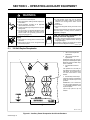
1 Insulating Gloves
2 Safety Glasses With Side
Shields
3 Welding Helmet
Wear dry insulating gloves, safety
glasses with side shields, and a
welding helmet with a correct shade
of filter (see ANSI Z49.1).
sb3.1 10/91
123
Figure 4-2. Safety Equipment

OM-481 Page 13
1 Work Clamp
Connect work clamp to a clean,
paint-free location on workpiece, as
close to weld area as possible.
Use wire brush or sandpaper to
clean metal at weld joint area. Use
chipping hammer to remove slag
after welding.
sb4.1 2/93
Tools Needed:
1
Figure 4-3. Work Clamp
Ref. ST-131 784-A
1 CC/CV Switch
Use switch to select type of weld
output.
Use constant current (CC) position
for SMAW and CAC-A.
Use constant voltage (CV) position
for wire feeding processes, GMAW,
SAW, and FCAW. When using CV
position, place Ampere Ranges
switch in CV position (see
Figure 4-5).
1
Figure 4-4. CC/CV Switch
CAUTION
ARCING can damage switch.
• Do not change Ampere Ranges switch position while welding.
Arcing inside switch can damage contacts, causing switch to fail.
rwarn6.1 2/93
1 Ampere Ranges Switch
Use switch to select weld output
range.
2 Amperage And Voltage Ad-
justment Control
Use control to adjust amperage
within range selected by Ampere
Ranges switch.
The numbers are a percentage of
the range selected and not an ac-
tual value.
Control may be adjusted while
welding.
1
2
Example Of Front Panel Amperage Control
Set Range Set Percentage Weld Output = 90 A DC
In Example:
Range = 55 to 125 A DC
Percentage Of Range = 50%
Weld Output = 90 A DC (50% of 55 to 125)
Figure 4-5. Amperage Controls

OM-481 Page 14
WARNING
ELECTRIC SHOCK can kill.
• Do not touch live electrical parts.
• Do not touch weld output terminals when engine is running.
• Do not touch electrode and work clamp at the same time.
rwarn7.1 9/91
1 Output (Contactor) Switch
Use switch to select way of control-
ling unit output.
For front panel control, place switch
in On position.
For remote control, place switch in
Remote position (see Section 3-9).
Weld output terminals are energized when Output
(Contactor) switch is On and engine is running.
1
Figure 4-6. Remote Controls
1 Amperage/Voltage Control
Switch
Use switch to select way of control-
ling amperage and voltage
adjustment.
For front panel control, place switch
in Panel position.
For remote control, place switch in
Remote position.
2 Remote Foot Control
3 Remote Amperage Control
See example below.
1
Example Of Combination Remote Amperage Control
Set Switches
Adjust Remote Control
Set Percentage
Min = 55 A DC/CC
Percentage Of Range = 50%
Max = 90 A DC/CC (50% of 55 to 125)
In Example:
3
S-0774 / S-0769
Set Range
Min (55 A DC/CC)
Max (90 A DC/CC)
2
Figure 4-7. Amperage/Voltage Control Switch

OM-481 Page 15
WARNING
INJECTING ETHER WHILE ENGINE IS RUNNING can damage engine.
• Do not use Ether Starting Aid while engine is running.
After installing cylinder, wait at least 10 minutes before use to let ether particles settle to prevent atomizer plugging.
rsb16.1* 4/92
1 Engine Control Switch
Use switch to start and stop engine.
To start, turn switch to Start position
and release as soon as engine
starts. Do not engage starter while
flywheel is rotating.
In Run position, engine runs at weld
speed all the time.
To stop engine, turn switch to Off
position.
If unit has optional overspeed shut-
down kit, engine stops automatical-
ly when speed exceeds normal
rpm.
2 Ether Starting Aid Switch
Push switch up and release while
cranking engine. Ether is sprayed
into engine manifold when switch is
released.
12
Figure 4-8. Engine Control Switch And Optional Ether Starting Aid Switch
1 Engine Hour Meter
Use meter to check total operating
hours (see Section 6-1).
2 Fuel Gauge
Use gauge to check fuel level in fuel
tank.
3 Battery Ammeter
Use ammeter to check amperage
output to the battery. The ammeter
reads near 0 (zero) when the en-
gine is running. If ammeter is at a
negative number, the battery is dis-
charging. Stop engine, and do not
run until problem is fixed.
4 Oil Pressure Gauge/Shut-
down Switch
Use gauge/switch to check oil pres-
sure. Normal operating pressure is
about 50 psi (345 kPa). If oil pres-
sure drops to 30 psi (207 kPa),
switch closes and engine stops.
5 Oil Temperature Gauge/Shut-
down Switch
Use gauge/switch to check oil tem-
perature. Normal operating temper-
ature is about 225°F (107° C). If oil
temperature rises to 250°F (121°
C), switch closes and engine stops.
rsb6.1* 2/92
12
345
Figure 4-9. Engine Hour Meter And Gauges

OM-481 Page 16
1 DC Voltmeter
Voltmeter displays voltage at the
weld output terminals, but not nec-
essarily the welding arc due to
cable resistance, poor connec-
tions, etc.
2 DC Ammeter
Ammeter displays amperage out-
put of unit.
1
2
Figure 4-10. Voltmeter And Ammeter
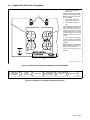
WARNING
BUILDUP OF SHIELDING GAS can harm health or kill.
• Shut off shielding gas supply when not in use.
warn1.1 9/91
1 Shielding Gas Cylinder
2 Valve
3 Gun Trigger
4 Foot Control
Open valve on cylinder just before
welding.
Gun trigger or foot control turns
weld output and gas flow on and off.
Close valve on cylinder when fin-
ished welding.
sb5.2 2/92 − S-0621-C
2
1
3
4
OR
Figure 4-11. Shielding Gas
Insert
Electrode
Into Holder
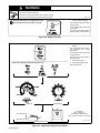
rsb8.1 9/92
Install &
Connect
Equipment
Select
Electrode
Put On
Personal Safety
Equipment
Set Controls Start Engine
Turn On Auxiliary
Equipment
Begin Welding
Figure 4-12. Sequence Of Shielded Metal Arc Welding (SMAW)
Turn On Auxiliary
Equipment
rsb7.1 9/92
Install &
Connect
Equipment
Install & Prepare
Wire Feeding
System
Put On
Personal Safety
Equipment
Set Controls
Turn On
Shielding Gas Start Engine
Turn On
Wire Feeder Begin Welding
Figure 4-13. Sequence Of Gas Metal Arc Welding (GMAW)
Page is loading ...
Page is loading ...
Page is loading ...
Page is loading ...
Page is loading ...
Page is loading ...
Page is loading ...
Page is loading ...
Page is loading ...
Page is loading ...
Page is loading ...
Page is loading ...
Page is loading ...
Page is loading ...
Page is loading ...
Page is loading ...
Page is loading ...
Page is loading ...
Page is loading ...
Page is loading ...
Page is loading ...
Page is loading ...
Page is loading ...
Page is loading ...
Page is loading ...
Page is loading ...
Page is loading ...
Page is loading ...
Page is loading ...
Page is loading ...
Page is loading ...
Page is loading ...
Page is loading ...
Page is loading ...
Page is loading ...
Page is loading ...
Page is loading ...
Page is loading ...
Page is loading ...
-
 1
1
-
 2
2
-
 3
3
-
 4
4
-
 5
5
-
 6
6
-
 7
7
-
 8
8
-
 9
9
-
 10
10
-
 11
11
-
 12
12
-
 13
13
-
 14
14
-
 15
15
-
 16
16
-
 17
17
-
 18
18
-
 19
19
-
 20
20
-
 21
21
-
 22
22
-
 23
23
-
 24
24
-
 25
25
-
 26
26
-
 27
27
-
 28
28
-
 29
29
-
 30
30
-
 31
31
-
 32
32
-
 33
33
-
 34
34
-
 35
35
-
 36
36
-
 37
37
-
 38
38
-
 39
39
-
 40
40
-
 41
41
-
 42
42
-
 43
43
-
 44
44
-
 45
45
-
 46
46
-
 47
47
-
 48
48
-
 49
49
-
 50
50
-
 51
51
-
 52
52
-
 53
53
-
 54
54
-
 55
55
-
 56
56
-
 57
57
-
 58
58
-
 59
59


Miller KD536837 Owner's manual
- Category
- Welding System
- Type
- Owner's manual
- This manual is also suitable for
Ask a question and I''ll find the answer in the document
Finding information in a document is now easier with AI
Related papers
-
Miller KC227524 Owner's manual
-
-
-
-
-
-
-
-
-
Other documents
-
Hobart Welding Products PowerPak User manual
-
Simply Conserve L13DL56AP-30K-1 Installation guide
-
Toro Load Control, RT1200 Traction Unit Installation guide
-
Blue Sea Systems 8378 Operating instructions
-
Simplicity 030207-0 User manual
-
Murphy OS-77R-I User manual
-
PowerWalker Basic VI 1500 STL UK Owner's manual
-
Miller Electric DC 650 User manual
-
Smithco 7000 Tournament Ultra XXL Roller Owner's manual
-
DKS 3-Button Wiring User manual