Page is loading ...

EL-5400-HBT
HDMI / VGA / Display Port Presentation Switch & Scaler
with HDMI & HDBaseT™ LITE Outputs
OPERATION MANUAL


3
DISCLAIMERS
The information in this manual has been carefully checked and is
believed to be accurate. CYP (UK) Ltd assumes no responsibility for any
infringements of patents or other rights of third parties which may result
from its use.
CYP (UK) Ltd assumes no responsibility for any inaccuracies that may be
contained in this document. CYP (UK) Ltd also makes no commitment to
update or to keep current the information contained in this document.
CYP (UK) Ltd reserves the right to make improvements to this document
and/or product at any time and without notice.
COPYRIGHT NOTICE
No part of this document may be reproduced, transmitted, transcribed,
stored in a retrieval system, or any of its part translated into any language
or computer file, in any form or by any means—electronic, mechanical,
magnetic, optical, chemical, manual, or otherwise—without express
written permission and consent from CYP (UK) Ltd.
© Copyright 2011 by CYP (UK) Ltd.
All Rights Reserved.
Version 1.1 August 2011
TRADEMARK ACKNOWLEDGMENTS
All products or service names mentioned in this document may be
trademarks of the companies with which they are associated.

4
SAFETY PRECAUTIONS
Please read all instructions before attempting to unpack, install or operate
this equipment and before connecting the power supply.
Please keep the following in mind as you unpack and install this
equipment:
• Always follow basic safety precautions to reduce the risk of fire,
electrical shock and injury to persons.
• To prevent fire or shock hazard, do not expose the unit to rain,
moisture or install this product near water.
• Never spill liquid of any kind on or into this product.
• Never push an object of any kind into this product through any
openings or empty slots in the unit, as you may damage parts inside
the unit.
• Do not attach the power supply cabling to building surfaces.
• Use only the supplied power supply unit (PSU). Do not use the PSU if
it is damaged.
• Do not allow anything to rest on the power cabling or allow any
weight to be placed upon it or any person walk on it.
• To protect the unit from overheating, do not block any vents or
openings in the unit housing that provide ventilation and allow for
sufficient space for air to circulate around the unit.
REVISION HISTORY
VERSION NO. DATE SUMMARY OF CHANGE
v2.00 10/08/2018 First release

5
CONTENTS
1. Introduction ...........................................6
2. Applications ...........................................6
3. Package Contents ..................................6
4. System Requirements ...........................7
5. Features ..................................................7
6. Operation Controls and Functions .......8
6.1 Front Panel ................................................... 8
6.2 Rear Panel ..................................................... 9
6.4 OSD Menu ..................................................11
6.5 IR Cable Pin Assignment .......................16
6.6 RS-232 Protocol ........................................ 16
6.7 RS-232 and Telnet Commands ............17
6.8 Telnet Control ............................................26
6.9 WebGUI Control .......................................28
7. Connection Diagram .......................... 30
8. Specifications ...................................... 31
8.1 Technical Specifications ........................31
8.2 Video Specifications................................32
8.3 HDBaseT Specifications ......................... 34
9. Acronyms ............................................. 35

6
1. INTRODUCTION
This HDMI/DP/HDBaseT to HDMI/HDBaseT Scaler supports five inputs
including HDMI, VGA, and DisplayPort. Any selected source will be scaled
to your preferred resolution for output over HDMI and HDBaseT. HD
resolutions up to 1080p@60Hz are supported. This unit also provides
audio application flexibility by including multiple unbalanced audio
inputs, a 1/4” mic input (with support for optional 48V phantom power)
and one line out port.
This unit contains an audio DSP engine with auto-mixer and auto-gain
functionality, allowing for the mic source to be mixed with the audio from
one of the video sources while reducing the background audio in order to
enhance the primary audio source. The HDBaseT output provides 24V PoC
(Power over Cable) allowing compatible PoC powered HDBaseT Receivers
to operate without needing a local power connection. This unit can be
easily controlled and configured through the front panel with OSD, IR
remote control, RS-232, Telnet, or WebGUI. This unit is an ideal solution for
presentations in classrooms and conference rooms.
2. APPLICATIONS
Analogue and digital source integration
Upscaling standard definition video for high-definition displays
Conference centers
Lecture halls
Schools and universities
3. PACKAGE CONTENTS
1×HDMI/DP/VGA to HDMI/HDBaseT Scaler
1×Remote Control (CR-165)
1×IR Blaster Cable
1×IR Extender Cable
1×19
″
Rack Mounting Kit
1×15-pin D-sub Male to 3 RCA Cable
1×3.5mm to 9-pin D-sub Male Cable
1×6-pin Terminal Block
1×24V/1.25A Power Adaptor

7
1×Operation Manual
4. SYSTEM REQUIREMENTS
Source equipment such as media players, video game consoles, PCs,
or set-top boxes.
HDMI receiving equipment such as HDTVs, monitors or audio
amplifiers and/or a compatible HDBaseT Receiver with 24V PoC
support.
The use of industry standard Cat.6, Cat.6a or Cat.7 cable is highly
recommended.
The use of “Premium High Speed HDMI” cables is highly
recommended.
5. FEATURES
HDMI, DVI and DisplayPort compliant
HDCP 1.4 compliant
Multiple video and audio inputs: 2×HDMI, 2×VGA,1×DisplayPort,
3×Unbalanced audio, 1×Mic audio (w/ 48V phantom power option)
HDMI and HDBaseT outputs (mirrored)
Inputs support HD resolutions up to 1080p@60Hz and PC resolutions
from VGA to WUXGA
Outputs support resolutions up to 1080p@60Hz
Supports pass-through of LPCM 2.0 audio
Audio DSP with auto mixer and gain control for mixing audio and
reducing background audio
HDBaseT feature support: High-Definition video and audio, 24V
PoC (Power over Cable) and control (Bi-directional IR & RS-232 pass
through)
HDBaseT output provides 24V PoC to power to compatible HDBaseT
Receivers
EDID management support
Supports IR In and IR Out to receive or transmit IR signals from
compatible Receivers with bi-directional IR
Remote control provides discrete input source selection
Supports control via WebGUI, Telnet, IR remote and RS-232

8
6. OPERATION CONTROLS AND FUNCTIONS
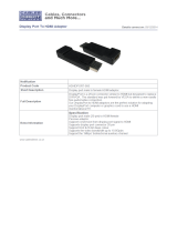
6.1 Front Panel
LOCK
+
-
ENTER
MENU
SELECT
HDMI
1
DPHDMI
2
1
PC
2
PC LOCK
81
2
3 4 5 6 7
1
POWER LED: This LED will illuminate to indicate the unit is on and
receiving power.
2
IR WINDOW: Accepts IR signals from the included IR remote for
control of this unit only.
3
ENTER: Press to confirm a selection within the OSD or to go deeper
into a menu item.
4
MENU: Press to enter the OSD menu, or to back out from menu items.
5
-/+ (MINUS/PLUS): Press to move up and down or adjust selections
within OSD menus.
Note: Pressing “Menu” and “+” together will reset the output resolution
to XGA@60Hz (1024×768). Pressing “Menu” and “-” together will reset the
output resolution to 720p@60Hz.
6
SELECT: Press this button to sequentially switch through the available
inputs.
7
LOCK: Press to lock all button functions on the front panel. Press again
to release the lock function. The "LOCK" LED will be lit when the front
panel is in the locked state.
8
LEDs: These LEDs indicate the currently selected source as well as the
current front panel lock state.

9
6.2 Rear Panel
PC 2PC 1LINE INMIC INSERVICEIR OUT IR IN RS232
COM PORT
LINE OUT
CAT5e/6/7 OUTHDMI OUTHDMI 2HDMI 1 DISPLAY PORT
INPUT CONTROL
C12345
CONTROL
OFF
ON
PHANTOM
PC 2PC 1
DC 24V
13
15
1
2
3 4 5 6 7 8 9 10 11 12 14
1
HDMI IN 1~2: Connect to HDMI source equipment such as a media
players, game consoles or set-top boxes.
DisplayPort IN: Connect to DisplayPort source equipment such as a
PC or laptop.
PC IN 1~2: Connect to VGA source equipment such as a PC or laptop.
YUV sources, such as DVD players, are also supported with the use of
a 15-pin to 3-RCA adapter when the port has the "COMP IN" mode
turned on in the OSD.
2
HDMI OUT: Connect to an HDMI TV, monitor or amplifier for digital
video and audio output.
CAT5e/6/7 OUT: Connect to a compatible, 24V PoC supporting,
HDBaseT Receiver for remote video and audio output.
3
SERVICE: This slot is reserved for firmware update use only.
4
LINE OUT: Connect to powered speakers or an amplifier for stereo
analogue audio output.
5
MIC IN: Connect a microphone for direct audio input. Phantom power
mics are supported.
6
PHANTOM/OFF/ON: Set the switch to “ON” for condenser mics (5V)
or “PHANTOM” for professional 48V phantom power mics. When the
switch is set to “OFF” the MIC input will be muted.
7
LINE IN: Connect to the stereo analogue output of a device such as a
CD player or PC. This audio will be used in place of the HDMI/DP audio
when “external” audio is selected in the OSD menu.
8
PC 1~2: Connect to the stereo analogue output of the device
connected to the associated VGA input port.

10
9
IR OUT: Connect to the provided IR Blaster to transmit IR signals to
devices within direct line-of-sight of the IR Blaster.
10
IR IN: Connect to the provided IR Extender to extend the IR control
range of remotely located devices. Ensure that the remote being used
is within direct line-of-sight of the IR Extender.
11
RS-232: Connect to a PC, laptop or other serial control device for the
extension of RS-232 signals to the connected HDBaseT Receiver.
12
INPUT CONTROL: This terminal block is used for direct source input
selection. Short the ground pin (marked as “C”) with any one of the
following pins to make an individual source selection (Pin 1=HDMI IN 1,
Pin 2=HDMI IN 2, Pin 3= DisplayPort IN, Pin 4=PC 1, and Pin 5= PC 2).
13
COM PORT: Connect directly to a PC, laptop or other serial control
device to send RS-232 commands to control the unit.
14
CONTROL: Connect directly, or through a network switch, to your PC/
laptop to control the unit via Telnet/WebGUI.
15
DC 24V: Plug the 24V DC power adapter into this port and connect it
to an AC wall outlet for power.
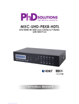
6.3 Remote Control
1
HDMI 1~2, DP & PC 1~2: Press any of
these buttons to switch immediately to
the corresponding input.
2
MENU: Access the OSD menu.
3
EXIT: Exit the OSD menu.
4
▲
/
▼
: Navigate up/down within the
OSD menu items.
◄
/
►
& VOL -/+: Adjust the selected
item’s parameters (+) or (-) within the
OSD menu or adjust output volume.
OK: Confirm your selections within the
OSD menu.
5
AUTO ADJUST: Automatically adjust
and center analogue PC sources.
6
RESET: Return to factory default
settings. (Ethernet settings are not
changed.)
CR-165
HDMI2 DP
MENU
OK
EXIT
PC2PC1
HDMI1
RESETAUTO
ADJUST
+
VOL
-
1
3
2
4
6
5

11
6.4 OSD Menu
LEVEL 1 LEVEL 2 LEVEL 3 LEVEL 4
DISPLAY SOURCE HDMI1
HDMI2
DP
PC1
PC2
SIZE OVER SCAN
FULL
FOLLOW INPUT
PAN SCAN
LETTER BOX
UNDER 2
UNDER 1
RESOLUTION 640×480
800×600
1024×768
1280×768
1360×768
1280×720
1280×800
1280×1024
1440×900
1400×1050
1680×1050
1600×1200
1920×1080
1920×1200
720×480P
1280×720P60

12
LEVEL 1 LEVEL 2 LEVEL 3 LEVEL 4
DISPLAY(CONT.) RESOLUTION(CONT.) 1920×1080i60
1920×1080P60
720×576P
1280×720P50
1920×1080i50
1920×1080P50
NATIVE OUT1
NATIVE OUT2
HDCP ON INPUT HDMI1 ON
OFF
HDMI2 ON
OFF
DP ON
OFF
COMP IN PC [Enable
YUV support]
COMP IN PC1 ON
OFF
COMP IN PC2 ON
OFF
PICTURE CONTRAST 0~60 (30)
BRIGHTNESS 0~60 (30)
RED 0~1023 (512)
GREEN 0~1023 (512)
BLUE 0~1023 (512)
HUE* 0~60 (30)
SATURATION* 0~60 (30)
SHARPNESS* 0~60 (10)
NOISE REDUCTION* OFF
LOW
MIDDLE
HIGH

13
LEVEL 1 LEVEL 2 LEVEL 3 LEVEL 4
PICTURE (CONT.) FINETUNE** AUTO ADJUST NO/YES
H-POSITION 0~60 (30)
V-POSITION 0~60 (30)
PHASE 0~30 (16)
CLOCK 700~2300 (1344)
WXGA/XGA WXGA
XGA
RESET NO/YES
AUDIO MIXER OFF
MIC
MIC VOLUME 0~100 (70)
DELAY OFF
40ms
110ms
DELAY 150ms
MUTE OFF
ON
OUTPUT VOLUME 0~100 (80)
EMBEDDED AUDIO HDMI1 AUTOMATIC
EMBEDDED
Analogue
HDMI2 AUTOMATIC
EMBEDDED
Analogue
DP AUTOMATIC
EMBEDDED
Analogue
INPUT VOLUME HDMI1 0~100 (100)
HDMI2 0~100 (100)
DP 0~100 (100)

14
LEVEL 1 LEVEL 2 LEVEL 3 LEVEL 4
AUDIO (CONT.) INPUT VOLUME (CONT.) PC1 0~100 (100)
PC2 0~100 (100)
MISCELLANY AUTO INPUT OFF
SCAN ALL
AUTO SYNC OFF OFF
FAST [10sec]
SLOW [120sec]
OSD H POSITION 1~100 (50)
V POSITION 1~100 (50)
TIMER 10~100sec (100)
TRANSPARENCY 1~100 (50)
DISPLAY INFO
ON
OFF
ETHERNET IP MODE STATIC
DHCP
IP ADDRESS 0~255
SUBNET 0~255
GATEWAY 0~255
CONTROL PORT 1~65535 (50000)
MAC ADDRESS
EDID SETUP EDID FROM NONE
OUT1
OUT2
DEFAULT
EDID TO NONE
HDMI1
HDMI2
DP
EDID COPY NO/YES

15
LEVEL 1 LEVEL 2 LEVEL 3 LEVEL 4
FAC TORY RESET NO/YES
UPDATE SYSTEM USB UPDATE
INFORMATION INPUT RES.
INPUT HDCP
OUTPUT RES.
OUTPUT1 HDCP
OUTPUT2 HDCP
IP ADDRESS
VERSION
Note:
Values in Bold are factory default settings.
Commands with one asterisk (*) are only available for HDMI and DisplayPort
inputs. Commands with two asterisks (**) are only available for PC inputs.

16
6.5 IR Cable Pin Assignment
3
2
1
IR Blaster
Power
IR Signal
NC
3
1
2
IR Signal
Power
Ground
IR Extender
6.6 RS-232 Protocol
UNIT
►
◄
REMOTE CONTROLLER
Pin Assignment Pin Assignment
1 NC 1 NC
2 TxD 2 RxD
3 RxD 3 TxD
4 NC 4 NC
5 GND 5 GND
6 NC 6 NC
7 NC 7 NC
8 NC 8 NC
9 NC 9 NC
Baud Rate: 9600bps
Data Bits: 8
Parity: None
Flow Control: None
Stop Bits: 1

17
6.7 RS-232 and Telnet Commands
COMMAND DESCRIPTION
? List all commands.
s factory-reset Return to factory default settings.
r version Read FW version.
r source Read current input source.
s source N Set input source.
N = 0~4
0=HDMI 1
1=HDMI 2
2=DP
3=PC 1
4=PC 2
r lock Read lock button status.
s lock N Set lock button status.
N = 0, 1
0=Unlock
1=Lock
r output Read output resolution.
s output N Set output resolution.
N = 0~23
0=640×480
1=800×600
2=1024×768
3=1280×768
4=1360×768
5=1280×720
6=1280×800
7=1280×1024
8=1440×900
9=1400×1050
10=1680×1050

18
COMMAND DESCRIPTION
11=1600×1200
12=1920×1080
13=1920×1200
14=720×480P
15=1280×720P60
16=1920×1080I60
17=1920×1080P60
18=720×576P
19=1280×720P50
20=1920×1080I50
21=1920×1080P50
22=NATIVE OUT1
23=NATIVE OUT2
r size Read output aspect setting.
s size N Set output aspect.
N = 0~6
1=Full
2=Follow Input
3=Pan Scan
4=Letter Box
5=Under 2
6=Under 1
r hdmi1-hdcp Read HDCP status for HDMI 1.
s hdmi1-hdcp N Set HDCP mode for HDMI 1.
N = 0, 1
0=Enable
1=Disable
r hdmi2-hdcp Read HDCP status for HDMI 2.
s hdmi2-hdcp N Set HDCP mode for HDMI 2.
N = 0, 1
0=Enable
1=Disable

19
COMMAND DESCRIPTION
r dp-hdcp Read HDCP status for DisplayPort.
s dp-hdcp N Set HDCP mode for DisplayPort.
N = 0, 1
0=Enable
1=Disable
r contrast Read contrast setting.
s contrast N Set contrast.
N = 0~60
r brightness Read brightness setting.
s brightness N Set brightness.
N=0~60
r color-r Read red colour level.
s color-r N Set red colour level.
N=0~1023
r color-g Read green colour level.
s color-g N Set green colour level.
N=0~1023
r color-b Read blue colour level.
s color-b N Set blue colour level.
N=0~1023
r hue Read hue setting.
s hue N Set hue.
N=0~60
r saturation Read saturation setting.
s saturation N Set saturation.
N=0~60
r sharpness Read sharpness setting.
s sharpness N Set sharpness.
N=0~30

20
COMMAND DESCRIPTION
r nr Read noise reduction setting.
s nr N Set noise reduction level.
N = 0~3
0=Off
1=Low
2=Middle
3=High
s pc-auto 1 Activate auto size detection function for
the PC source.
s pc-reset 1 Return to the default settings for the PC
source.
r pc-h-pos Read horizontal position of PC source.
s pc-h-pos N Set horizontal position of the PC source.
N=0~60
r pc-v-pos Read vertical position of PC source.
s pc-v-pos N Set vertical position of the PC source.
N=0~60
r pc-phase Read PC source phase.
s pc-phase N Set PC source phase.
Values=0~30
r pc-wxga-xga Read PC WXGA/XGA status.
s pc-wxga-xga N Set WXGA/XGA preference.
N = 0, 1
0=WXGA
1=XGA
r mixer Read mixer status.
s mixer N Set Mic mixer state.
N = 0, 1
0=Off
1=Mic
/