-20
Making General Settings for
the Network
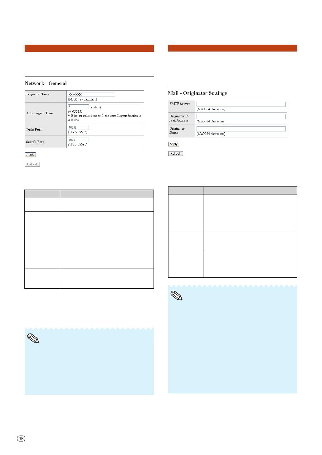
(Network - General)
On this screen, you can make general
settings relating to the network.
Items Description
Projector
Name
Setting the projector name.
Auto Logout
Time
Setting the time interval in which the
projector will be automatically
disconnected from the network in units
of a minute (from 1 to 65535 minutes).
If the set value is made 0, the Auto
Logout function is disabled.
Data Port Setting the TCP port number used
when exchanging data with the
projector (from 1025 to 65535).
Search Port Setting the port number used when
searching for the projector (from 1025
to 65535).
After clicking the “Apply” button, the set
values appear. Confi rm that the values are
set properly, and then click the “Confi rm”
button.
After setting items, wait for about 15 seconds
and then re-access.
Projector Name can be up to 12 characters.
You can input the characters below:
A-Z, 0-9, -, _, (,), space
(When “a-z” are input, they are converted to
“A-Z” automatically.)
•
•
•
Note
Setting for Sending E-mail
when an Error Occurs
(Mail – Originator Settings)
On this screen, you can make settings for
sending e-mail to report when the
projector has generated an error.
Items Setting example / Remarks
SMTP Server Setting an SMTP server address for e-
mail transmission.
e.g.1: 192.168.150.253
e.g.2: smtp123.sharp.co.jp
* When using a domain name, make
settings for the DNS server.
Originator E-
mail Address
Setting the projector's e-mail address.
The e-mail address set here becomes
Originator E-mail Address.
Originator
Name
Setting the sender's name. The name
set here appears in the “Originator
Name” column of the body of the
message.
SMTP Server, Originator E-mail Address and
Originator Name can be up to 64 characters.
You can input the characters below:
SMTP Server and Originator E-mail Address:
a-z, A-Z, 0-9, !, #, $, %, &, *, +, -, /, =, ?, ^, {, |, },
~
, _, ', ., @, `
(You can input “@” only one time for “Originator
E-mail Address”.)
Originator Name : a-z, A-Z, 0-9, -, _, (,), space
If the settings of “3. Setting up a Network
Connection for the Projector” on pages
15
and 16 are incorrectly set, e-mail will not be
sent.
•
•
•
Note
Controlling the Projector via LAN


