DBI-SALA 2200109 Operating instructions

Type
Operating instructions
© Copyright 2012, DB Industries, Inc.
This anchor pad must be used in conju n
with a DBI-SALA SCVA primary anchor
Do not disconnect vacuum hose while chor
pad is in use. Do not connect compr ir to
the vacuum inlet on this anchor pad.
PRIMARY
NCHOR PAD
VACUUM ET
WARNING
X
3,000 psi
(20 MPa)
M
L
-
(800)328-6146
www.capitalsafety.com
A CAPITAL SAFETY BRAND
R
Self Contained Vacuum Anchor
INSPECTION
Before each use, inspect vacuum
anchor for damaged, worn, loose, or
missing components. Inspect vacuum
pads and hoses for cuts or other
damage. Periodically, according to
conditions of use, a competent person
other than the user must inspect the
vacuum anchor. See user manual for
inspection and factory service
schedule. Do not use if inspection
reveals an unsafe condition.
80-150 PSI
Capacity:
One user, 310 lbs. (141 Kg)
Anchor strength:
3,000 lbs. minumum
Materials of construction:
Aluminum
Natural Rubber/Polybutadiene
Patent No:
US 6,547,033
GB 2,313,396
AU 712,249
SPECIFICATIONS
DEPRESS BUTTON
TO BYPASS ALARM
OBI OK
RELEASE
ATTACH
DATE INITIAL
Structure to which the vacuum anchor is
attached must be capable of supporting the
loads imposed by the vacuum anchor due to
fall arrest, see user manual. Locate vacuum
anchor and rig fall arrest system to minimize
free fall and swing fall hazards. Ensure
sufficient clearance exists in the work area
to avoid striking an object or lower level
should a fall occur. Clean area where pad is
to be attached of loose debris and excess
moisture before applying vacuum. A full body
harness is recommended for use with this
device. Avoid lanyard contact with sharp
edges. If alarm sounds, move to a safe area
and disconnect from vacuum anchor until
normal operation resumes. For use by trained
persons only. See user manual for more
details. Do not remove this label.
Manufacturer's instructions must be read and
understood prior to use. Instructions supplied
with this product at time of shipment must be
followed. This anchorage device must only be
installed and used under the super- vision
of a qualified person as part of a complete
personal fall arrest system, which maintains
a safety factor of at least two. Do not use
vacuum anchor where pad will not seal properly
or leakage is apparent. Do not attach vacuum
anchor to structurally inappropriate materials
or surfaces. Refer to user manual for temperature
operation limits. Alteration or misuse of this
product, or failure to follow instructions may
result in serious injury or death.
TM
WARNING WARNING
LOG
ct is i-Safe enabled and contains an
c tag that can be read by compatible
- providing inspection logs, inventory
ement and other safety information.
X
M
L
-
(800)328-6146
www.capitalsafety.com
A CAPITAL SAFETY BRAND
R
Self Contained Vacuum Anchor
INSPECTION
Before each use, inspect vacuum
anchor for damaged, worn, loose, or
missing components. Inspect vacuum
pads and hoses for cuts or other
damage. Periodically, according to
conditions of use, a competent person
other than the user must inspect the
vacuum anchor. See user manual for
inspection and factory service
schedule. Do not use if inspection
reveals an unsafe condition.
80-150 PSI
Capacity:
One user, 310 lbs. (141 Kg)
Anchor strength:
3,000 lbs. minumum
Materials of construction:
Aluminum
Natural Rubber/Polybutadiene
Patent No:
US 6,547,033
GB 2,313,396
AU 712,249
SPECIFICATIONS
Do not use ry anchor
pad unless nchor pad is
attached to ng surface
and vacuum indicates green.
DEPRESS BUTTON
TO BYPASS ALARM
SEC ARY
ANC PAD
ING
OBI OK
RELEASE
ATTACH
Structure to which the vacuum anchor is
attached must be capable of supporting the
loads imposed by the vacuum anchor due to
fall arrest, see user manual. Locate vacuum
anchor and rig fall arrest system to minimize
free fall and swing fall hazards. Ensure
sufficient clearance exists in the work area
to avoid striking an object or lower level
should a fall occur. Clean area where pad is
to be attached of loose debris and excess
moisture before applying vacuum. A full body
harness is recommended for use with this
device. Avoid lanyard contact with sharp
edges. If alarm sounds, move to a safe area
and disconnect from vacuum anchor until
normal operation resumes. For use by trained
persons only. See user manual for more
details. Do not remove this label.
Manufacturer's instructions must be read and
understood prior to use. Instructions supplied
with this product at time of shipment must be
followed. This anchorage device must only be
installed and used under the super- vision
of a qualified person as part of a complete
personal fall arrest system, which maintains
a safety factor of at least two. Do not use
vacuum anchor where pad will not seal properly
or leakage is apparent. Do not attach vacuum
anchor to structurally inappropriate materials
or surfaces. Refer to user manual for temperature
operation limits. Alteration or misuse of this
product, or failure to follow instructions may
result in serious injury or death.
WARNING WARNING
INSPECTION LOG
DATE DATEINITIAL INITIAL
TM
This product is i-Safe enabled and contains an
electronic tag that can be read by compatible
readers - providing inspection logs, inventory
management and other safety information.
X
(800)328-6146
www.capitalsafety.com
A CAPITAL SAFETY BRAND
R
Self Contained Vacuum Anchor
Capacity:
One user, 310 lbs. (141 Kg)
Anchor strength:
3,000 lbs. minumum
Materials of construction:
Aluminum
Natural Rubber/Polybutadiene
Patent No:
US 6,547,033
GB 2,313,396
AU 712,249
SPECIFICATIONS
RELEASE
ATTACH
Structure to which the vacuum anchor is
attached must be capable of supporting the
loads imposed by the vacuum anchor due to
fall arrest, see user manual. Locate vacuum
anchor and rig fall arrest system to minimize
free fall and swing fall hazards. Ensure
sufficient clearance exists in the work area
to avoid striking an object or lower level
should a fall occur. Clean area where pad is
to be attached of loose debris and excess
moisture before applying vacuum. A full body
harness is recommended for use with this
device. Avoid lanyard contact with sharp
edges. If alarm sounds, move to a safe area
and disconnect from vacuum anchor until
normal operation resumes. For use by trained
persons only. See user manual for more
details. Do not remove this label.
Manufacturer's instructions must be read and
understood prior to use. Instructions supplied
with this product at time of shipment must be
followed. This anchorage device must only be
installed and used under the super- vision
of a qualified person as part of a complete
personal fall arrest system, which maintains
a safety factor of at least two. Do not use
vacuum anchor where pad will not seal properly
or leakage is apparent. Do not attach vacuum
anchor to structurally inappropriate materials
or surfaces. Refer to user manual for temperature
operation limits. Alteration or misuse of this
product, or failure to follow instructions may
result in serious injury or death.
WARNING WARNING
TM
This product is i-Safe enabled and contains an
electronic tag that can be read by compatible
readers - providing inspection logs, inventory
management and other safety information.
ING
SEC ARY
ANC PAD
Do not use ry anchor
pad unless nchor pad is
attached to ng surface
and vacuum indicates green.
INITIALINITIAL DATEDATE
INSPECTION LOG
Before each use, inspect vacuum
anchor for damaged, worn, loose, or
missing components. Inspect vacuum
pads and hoses for cuts or other
damage. Periodically, according to
conditions of use, a competent person
other than the user must inspect the
vacuum anchor. See user manual for
inspection and factory service
schedule. Do not use if inspection
reveals an unsafe condition.
INSPECTION
MANUAL DE INSTRUCCIONES DEL USUARIO
SISTEMA AUTÓNOMO DE ANCLAJE AL VACÍO
Este manual se proporciona como instructivo del fabricante, y debe usarse como parte de un programa de capacitación para los
empleados, tal como lo requiere la Administración de Salud y Seguridad Laboral de Estados Unidos (OSHA, por su sigla en inglés).
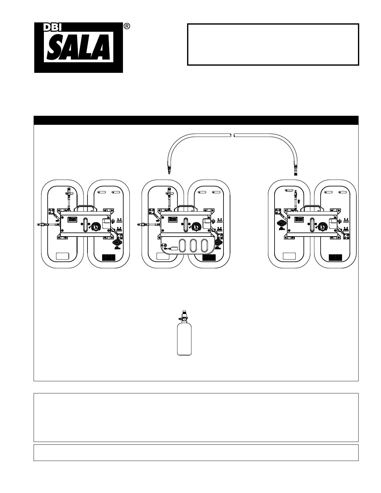
Figura 1 - Sistema autónomo de anclaje al vacío
ADVERTENCIA: Este producto es parte de un sistema de sujeción personal, posición de trabajo, suspensión o
rescate. Tales instrucciones deberán ser entregadas a los usuarios y a los integrantes del equipo de rescate
(véase la sección 8.0 Terminología). Antes de utilizarlo, el usuario debe leer y comprender estas instrucciones,
o bien, pedir que se las expliquen. El usuario debe leer y seguir las instrucciones del fabricante al usar cada
componente o pieza del sistema. Para el uso y mantenimiento correcto de este producto, se deben seguir las
instrucciones del fabricante. La modicación o el uso incorrecto de este producto, así como el incumplimiento de
las instrucciones, pueden causar heridas graves e, incluso, la muerte.
IMPORTANTE: Ante cualquier duda sobre el uso, el cuidado o la compatibilidad de este equipo con la aplicación que desea
darle, comuníquese con DBI‑SALA.
CILINDRO A BORDO
2200078
MANGUERA SECUNDARIA
2200130
SISTEMA AUTÓNOMO DE
ANCLAJE AL VACÍO MOBI-LOK
2200094
SISTEMA AUTÓNOMO DE ANCLAJE AL
VACÍO MOBI-LOK CON ACCESORIO DE
CILINDRO A BORDO
2200095
BASE DE ANCLAJE
SECUNDARIA
2200096
Instrucciones para los productos de la serie:
Sistema autónomo de anclaje al vacío Mobi-Lok
(Consulte los números de modelo

Formulario: 5902386
Rev: B
2
 
1.1 PROPÓSITO: El sistema autónomo de anclaje al vacío Mobi-Lok ha sido diseñado para usarse como conector de anclaje
para la conexión de un sistema personal de protección contra caídas para el personal que trabaja en aviones y otras
estructuras. Vea las guras 2 y 3 para conocer las aplicaciones típicas de detención de caídas y sujeción.
Figura 2 - Aplicaciones - sujeción por encima de la cabeza
Figura 3 - Aplicaciones - sujeción a la supercie de trabajo
1.2 LIMITACIONES:
A. ESTRUCTURA DE ANCLAJE: La superficie a la cual se sujeta el sistema autónomo de anclaje al vacío Mobi-
Lok debe seleccionarse de conformidad con las limitaciones y requisitos de fuerza especificados en este manual.
Consulte la sección 2.5 para obtener más información.
B. SISTEMA PERSONAL DE DETENCIÓN DE CAÍDAS: Los sistemas personales de detención de caídas usados con
el sistema autónomo de anclaje al vacío Mobi-Lok deben satisfacer los requisitos del sistema especificados en la
sección 2.1 de este manual. Debe usarse un acollador amortiguador DBI-SALA Force2 con el sistema autónomo de
anclaje al vacío Mobi-Lok, a menos que DBI-SALA autorice lo contrario (vea la instrucción 5908550). Consulte con
DBI-SALA si desea usar otro tipo de sistema secundario de conexión de acollador.
C. CAPACIDAD: El sistema autónomo de anclaje al vacío Mobi-Lok está diseñado para personas con un peso total
(persona con ropa, herramientas, etc.) no mayor a 141 kg (310 lb). Sólo puede conectarse un sistema de detención
de caídas a un sistema autónomo de anclaje al vacío Mobi-Lok.
Vacío
Ancla
Amortiguador Acollador
Superficie de trabajo
Riesgo de
caída
Arnés de cuerpo entero
Superficie de trabajo
Vacío
Ancla
Riesgo de caída
Riesgo de caída
Superficie de
trabajo
Arnés de cuerpo entero
Mecanismo de retención - Impide que el usuario
llegue a un riesgo de caída.
Detención de caída - El usuario puede
llegar a un riesgo de caída.
Mecanismo de retención - Impide que el usuario
llegue a un riesgo de caída.
Detención de caída - El usuario puede
llegar a un riesgo de caída.
Ancla al vacío
Amortiguador
Acollador
Riesgo de caída
Superficie
de trabajo
Arnés de cuerpo
entero
Ancla al vacío
Amortiguador
Acollador
Amortiguador
Acollador
3
D. ESPACIO LIBRE DE CAÍDA: Debe haber suficiente espacio libre debajo del usuario para poder detener una caída y
evitar que se golpee contra un objeto o contra el piso. El espacio requerido depende de los siguientes factores:
Elevación del anclaje al vacío • Longitud del sistema de conexión secundario
Distancia de desaceleración • Movimiento del elemento accesorio del arnés
Altura del operario • Distancia de la caída libre
Véase más información en las instrucciones del fabricante del sistema secundario personal de detención de caídas.
E. RIESGOS AMBIENTALES: El uso de este equipo en ambientes peligrosos puede requerir precauciones adicionales
para reducir la posibilidad de lesiones al usuario o daños al equipo. Los riesgos posibles incluyen, entre otros:
calor, frío extremo, sustancias químicas cáusticas o corrosivas, líneas de alta tensión, gases explosivos o tóxicos,
maquinaria en movimiento y bordes afilados.
F. CAPACITACIÓN: Este equipo tiene por objeto ser instalado y utilizado por personas capacitadas en su aplicación y
uso.
1.3 NORMAS VIGENTES: Para obtener más información sobre este equipo y los componentes de sistema relacionados,
consulte las normas nacionales, incluidos el conjunto de normas sobre protección contra caídas ANSI Z359 (.0, .1, .2, .3
y .4), las normas ANSI A10.32 y los requisitos locales, estatales y federales (OSHA) que regulan la seguridad laboral.
 
2.1 SISTEMA PERSONAL DE DETENCIÓN DE CAÍDAS:
A. COMPONENTES Y SISTEMAS SECUNDARIOS: El sistema autónomo de anclaje al vacío Mobi-Lok ha sido
diseñado para usarse con componentes y sistemas secundarios aprobados por DBI-SALA. Los componentes o
sistemas secundarios no aprobados pueden ser incompatibles con el sistema autónomo de anclaje al vacío Mobi-
Lok, lo cual podría afectar la seguridad y fiabilidad de todo el sistema. Los sistemas personales de detención de
caídas deben cumplir con los requisitos correspondientes locales, estatales y federales (OSHA). Con este sistema
debe usarse un arnés de cuerpo entero.
B. ACOLLADOR CON AMORTIGUADOR: Debe usarse un acollador amortiguador DBI-SALA Force2 con este sistema,
a menos que DBI-SALA autorice lo contrario. Para mantener un factor de seguridad mínimo de 2, el sistema
personal de detención de caídas debe limitar las fuerzas de detención de caídas a 6,2 kN (1400 lb) (cumple con
el límite de fuerza de detención de la OSHA de 8,0 kN [1800 lb], para sistemas con arnés de cuerpo completo). El
sistema debe estar instalado de manera que limite la caída libre a 1,8 m (6 pies) o menos. Algunas aplicaciones
pueden requerir que el sistema autónomo de anclaje al vacío Mobi-Lok sea sujetado al nivel de los pies en la
superficie de trabajo. Con esta configuración es posible una caída libre de más de 1,8 m (6 pies). Si se excede
la caída libre de 1,8 m (6 pies), la OSHA exige que el empleador documente, con datos de prueba, que no se
excederán las fuerzas máximas permitidas de detención de caídas, y que el sistema personal de detención de caídas
funcionará de manera correcta. DBI-SALA ha verificado mediante pruebas que el acollador amortiguador Force2, en
caídas libres de hasta 3,7 m (12 pies), no tendrá fuerzas de detención que excedan 6,2 kN (1400 lb). Los resultados
de las pruebas se especifican en el manual de instrucciones para el usuario del acollador amortiguador Force2 (núm.
5908550). Consulte con DBI-SALA si desea usar otro tipo de sistema secundario de conexión de acollador.
2.2 SISTEMA DE SUJECIÓN: Los sistemas de sujeción deben cumplir con los requisitos de los sistemas personales de
detención de caídas especicados en la sección 2.1.
2.3 FUENTE DE AIRE COMPRIMIDO: Para que este sistema funcione, requiere una fuente constante de aire o nitrógeno
comprimido, que suministre de 550 a 1035 kPa (80 a 150 psi). Esta fuente puede ser un compresor que suministre aire
al taller, un cilindro de aire comprimido o un cilindro de nitrógeno comprimido. Si tiene dudas acerca de si su fuente de
aire comprimido es apropiada, comuníquese con DBI-SALA.
2.4 COMPATIBILIDAD DE LOS CONECTORES: Los conectores (ganchos, mosquetones y argollas D) deben ser capaces
de soportar al menos 22,2 kN (5000 lb). Los conectores deben ser compatibles con todos los puntos de sujeción,
incluyendo el sistema autónomo de anclaje al vacío y otros componentes del sistema. Los conectores no compatibles
pueden soltarse accidentalmente. Los conectores deben ser compatibles en cuanto a tamaño, forma y resistencia. Deben
usarse conectores de seguridad con este equipo.
2.5 ESTRUCTURA DEL ANCLAJE: Las normas OSHA 1910.66 y 1926.500 establecen que: Los anclajes usados para
conectar un sistema personal de detención de caídas deberán ser independientes de cualquier anclaje que se esté
usando para sostener o suspender plataformas y capaces de soportar un mínimo de 22.2 kN (5000 lb) por usuario,
o deberán estar diseñados, instalados y empleados como parte de un sistema personal de detención de caídas que
mantenga un factor de seguridad de por lo menos dos, y que esté supervisado por una persona calicada. Cuando se
instale más de un sistema autónomo de anclaje al vacío Mobi-Lok en la estructura, ésta deberá ser capaz de resistir las
fuerzas especicadas arriba para cada sistema autónomo de anclaje al vacío Mobi-Lok sujeto a la estructura.
4
2.6 SUJECIÓN A AERONAVES:
NO SUJETE EL SISTEMA AUTÓNOMO DE ANCLAJE AL VACÍO MOBI-LOK A:
Elementos compuestos o supercies no metálicas (a menos que lo autorice el fabricante de la aeronave)
Ventanillas de la cabina de pasajeros y la cabina del piloto
Puertas de pasajeros, emergencia o carga
Puertas de mantenimiento o acceso
Áreas alrededor de cortes que no tengan apoyo suciente de elementos estructurales (travesaños y
armazones)
Áreas fuera del recubrimiento de la zona interior del larguero de la caja de las alas (es decir, líneas "No
pisar")
Supercies de control móviles
FORMAS DE SUJECIÓN ACEPTABLES:
El sistema puede usarse en el fuselaje si está soportado por armazones y travesaños, y en la supercie
superior del ala, entre los largueros.
Si ocurre una caída, el área donde estaba sujeto el sistema autónomo de anclaje al vacío Mobi-Lok debe
retirarse de servicio y ser inspeccionada por una persona competente para comprobar la integridad
estructural.
2.7 SUJECIÓN A ESTRUCTURAS:
NO SUJETE EL SISTEMA AUTÓNOMO DE ANCLAJE AL VACÍO MOBI-LOK A:
Estructuras donde la base no sellará correctamente o donde hay fugas evidentes.
Materiales o supercies estructuralmente inapropiados.
Supercies porosas o disparejas que impedirán un sellado correcto.
Supercies muy sucias o grasosas que impedirán un sellado correcto.
 
ADVERTENCIA: Evite modicar este equipo o usarlo incorrectamente en forma intencional. Consulte con Capital Safety
al usar este equipo junto con componentes o sistemas secundarios que no estén descritos en este manual. Algunas
combinaciones de sistemas secundarios y componentes pueden interferir con el funcionamiento de este equipo. Tenga
cuidado al usar este equipo cerca de maquinaria en movimiento y riesgos de naturaleza eléctrica. No pase el acollador
alrededor de elementos estructurales pequeños
.
ADVERTENCIA: No use este sistema si usted no es capaz de tolerar el impacto de una detención de caída. La edad y
el estado de salud constituyen dos factores que afectan seriamente su capacidad de soportar las caídas. Las mujeres
embarazadas y los menores no deben utilizar este equipo.
3.1 ANTES DE CADA USO del equipo, inspecciónelo según la sección 5.0 de este manual.
3.2 PLANIFIQUE su sistema personal de detención de caídas antes de instalar y utilizar este equipo. Considere todos los
factores que afecten su seguridad durante el uso.
A. UBICACIÓN DEL SISTEMA: Determine la ubicación del sistema autónomo de anclaje al vacío Mobi-Lok antes
de comenzar el trabajo. Vea las figuras 2 y 3. Si no es posible instalarlo como un sistema de sujeción coloque el
sistema autónomo de anclaje al vacío Mobi-Lok de manera que se
minimicen las posibles caídas libres, situando el sistema autónomo
de anclaje Mobi-Lok por encima de la altura de la cabeza o limitando
la longitud y holgura del acollador. Se recomienda mantener el
sistema lo más corto posible. Proporcione acceso seguro hacia y
desde el sitio de trabajo.
B. ESPACIO LIBRE DE CAÍDA: Vea la figura 4. Debe hacer un
espacio libre suficiente en la trayectoria de una posible caída a fin de
evitar golpearse contra un objeto o un piso inferior. La cantidad de
espacio libre requerido depende de la aplicación. Vea el manual de
instrucciones para el usuario del acollador amortiguador Force2 para
obtener información sobre cómo calcular el espacio libre de caída.
Figura 4: Espacio libre de caída
Superficie de trabajo
Nivel inferior
u obstrucción
Espacio libre de caída
Véase Force2
Acollador amortiguador
Instrucciones
5
C. CAÍDAS EN MOVIMIENTO PENDULAR: Las caídas en
movimiento pendular ocurren cuando el punto de anclaje no está
directamente por encima o por debajo del punto donde ocurre la
caída. Véase la figura 5. La fuerza del golpe contra un objeto en
una caída en movimiento pendular puede causar heridas graves
o, incluso, la muerte. Minimice las caídas pendulares trabajando
lo más cerca posible del punto de anclaje. No permita que ocurra
una caída pendular si ésta supone una lesión.
D. BORDES FILOSOS: Evite trabajar en sitios donde partes del
sistema pudieran estar en contacto o roce contra bordes agudos
sin protección.
E. DESPUÉS DE UNA CAÍDA: Los componentes sometidos a las
fuerza de detención de una caída deberán retirarse de servicio y
destruirse, o devolverse a un centro de servicio autorizado para
inspección o reparación.
F. RESCATE: El empleador debe tener un plan de rescate cuando
utiliza este equipo. El empleador debe tener la capacidad de llevar a cabo un rescate de manera rápida y segura.
3.3 PREPARACIÓN DEL SISTEMA AUTÓNOMO DE ANCLAJE AL VACÍO MOBI-LOK PARA USO:
Consulte la gura 6 para la identicación de los componentes.
A. Base principal del sistema autónomo de anclaje al vacío Mobi-Lok, fuente externa de aire comprimido (2200094):
Paso 1. Antes de cada uso, inspeccione el sistema autónomo de anclaje al vacío Mobi-Lok conforme a la
sección 5.0 de este manual. Inspeccione todos los otros componentes de protección contra caídas
conforme a las instrucciones de los respectivos fabricantes.
Paso 2. Conexión de aire comprimido:
Conecte la manguera de aire comprimido a la fuente de aire o nitrógeno comprimido (550 a 1035 kPa
[80 a 150 psi]).
Conecte el otro extremo de la manguera de aire al conector de aire comprimido del sistema autónomo
de anclaje al vacío Mobi-Lok.
Compruebe que la válvula de control de sujeción y liberación del sistema autónomo de anclaje al vacío
Mobi-Lok esté en la posición de liberación (“Release”).
B. Base principal del sistema autónomo de anclaje al vacío Mobi-Lok, con cilindro de aire comprimido a bordo
(2200095):
Paso 1. Antes de cada uso, inspeccione el sistema autónomo de anclaje al vacío Mobi-Lok conforme a la
sección 5.0 de este manual. Inspeccione todos los otros componentes de protección contra caídas
conforme a las instrucciones de los respectivos fabricantes.
Paso 2. Conexión de aire comprimido:
Seleccione un cilindro de aire comprimido (2200078) con presión mínima de 1000 psi. Enrosque el
cilindro en el receptáculo localizado debajo al protector de la unidad de anclaje al vacío y apriete a mano.
Si el medidor del cilindro está en una posición que no permite leerlo, desenrosque el cilindro hasta un
giro completo a una posición que permita la lectura.
Compruebe que la válvula de control de sujeción y liberación del sistema autónomo de anclaje al vacío
Mobi-Lok esté en la posición de liberación (“Release”).
C. BASE SECUNDARIA DEL SISTEMA AUTÓNOMO DE ANCLAJE AL VACÍO MOBI-LOK (2200096):
Paso 1. Antes de cada uso, inspeccione el sistema autónomo de anclaje al vacío Mobi-Lok conforme a la
sección 5.0 de este manual. Inspeccione todos los otros componentes de protección contra caídas
conforme a las instrucciones de los respectivos fabricantes.
Paso 2. Conexión de vacío:
• Conecte la manguera secundaria (2200130) a la conexión de vacío de la base primaria.
• Conecte el otro extremo de la manguera a la conexión de vacío de la base secundaria
Compruebe que la válvula de control de sujeción y liberación de la base secundaria esté en la posición
de liberación (“Release”).
Figura 5: Caídas en movimiento pendular
6
Punto de conexión
de la argolla D
para el sistema de
protección contra
caídas
Botón de
anulación
de la alarma
sonora
Bandeja de
baterías
VISTA LATERAL DE LA BASE DEL SISTEMA
AUTÓNOMO DE ANCLAJE AL VACÍO MOBI-LOK
This anchor pad must be used in conju n
with a DBI-SALA SCVA primary anchor
Do not disconnect vacuum hose while chor
pad is in use. Do not connect compr ir to
the vacuum inlet on this anchor pad.
PRIMARY
NCHOR PAD
VACUUM ET
WARNING
X
3,000 psi
(20 MPa)
M
L
-
(800)328-6146
www.capitalsafety.com
A CAPITAL SAFETY BRAND
R
Self Contained Vacuum Anchor
INSPECTION
Before each use, inspect vacuum
anchor for damaged, worn, loose, or
missing components. Inspect vacuum
pads and hoses for cuts or other
damage. Periodically, according to
conditions of use, a competent person
other than the user must inspect the
vacuum anchor. See user manual for
inspection and factory service
schedule. Do not use if inspection
reveals an unsafe condition.
80-150 PSI
Capacity:
One user, 310 lbs. (141 Kg)
Anchor strength:
3,000 lbs. minumum
Materials of construction:
Aluminum
Natural Rubber/Polybutadiene
Patent No:
US 6,547,033
GB 2,313,396
AU 712,249
SPECIFICATIONS
DEPRESS BUTTON
TO BYPASS ALARM
OBI OK
RELEASE
ATTACH
DATE INITIAL
Structure to which the vacuum anchor is
attached must be capable of supporting the
loads imposed by the vacuum anchor due to
fall arrest, see user manual. Locate vacuum
anchor and rig fall arrest system to minimize
free fall and swing fall hazards. Ensure
sufficient clearance exists in the work area
to avoid striking an object or lower level
should a fall occur. Clean area where pad is
to be attached of loose debris and excess
moisture before applying vacuum. A full body
harness is recommended for use with this
device. Avoid lanyard contact with sharp
edges. If alarm sounds, move to a safe area
and disconnect from vacuum anchor until
normal operation resumes. For use by trained
persons only. See user manual for more
details. Do not remove this label.
Manufacturer's instructions must be read and
understood prior to use. Instructions supplied
with this product at time of shipment must be
followed. This anchorage device must only be
installed and used under the super- vision
of a qualified person as part of a complete
personal fall arrest system, which maintains
a safety factor of at least two. Do not use
vacuum anchor where pad will not seal properly
or leakage is apparent. Do not attach vacuum
anchor to structurally inappropriate materials
or surfaces. Refer to user manual for temperature
operation limits. Alteration or misuse of this
product, or failure to follow instructions may
result in serious injury or death.
TM
WARNING WARNING
LOG
ct is i-Safe enabled and contains an
c tag that can be read by compatible
- providing inspection logs, inventory
ement and other safety information.
X
M
L
-
(800)328-6146
www.capitalsafety.com
A CAPITAL SAFETY BRAND
R
Self Contained Vacuum Anchor
INSPECTION
Before each use, inspect vacuum
anchor for damaged, worn, loose, or
missing components. Inspect vacuum
pads and hoses for cuts or other
damage. Periodically, according to
conditions of use, a competent person
other than the user must inspect the
vacuum anchor. See user manual for
inspection and factory service
schedule. Do not use if inspection
reveals an unsafe condition.
80-150 PSI
Capacity:
One user, 310 lbs. (141 Kg)
Anchor strength:
3,000 lbs. minumum
Materials of construction:
Aluminum
Natural Rubber/Polybutadiene
Patent No:
US 6,547,033
GB 2,313,396
AU 712,249
SPECIFICATIONS
Do not use ry anchor
pad unless nchor pad is
attached to ng surface
and vacuum indicates green.
DEPRESS BUTTON
TO BYPASS ALARM
SEC ARY
ANC PAD
ING
OBI OK
RELEASE
ATTACH
Structure to which the vacuum anchor is
attached must be capable of supporting the
loads imposed by the vacuum anchor due to
fall arrest, see user manual. Locate vacuum
anchor and rig fall arrest system to minimize
free fall and swing fall hazards. Ensure
sufficient clearance exists in the work area
to avoid striking an object or lower level
should a fall occur. Clean area where pad is
to be attached of loose debris and excess
moisture before applying vacuum. A full body
harness is recommended for use with this
device. Avoid lanyard contact with sharp
edges. If alarm sounds, move to a safe area
and disconnect from vacuum anchor until
normal operation resumes. For use by trained
persons only. See user manual for more
details. Do not remove this label.
Manufacturer's instructions must be read and
understood prior to use. Instructions supplied
with this product at time of shipment must be
followed. This anchorage device must only be
installed and used under the super- vision
of a qualified person as part of a complete
personal fall arrest system, which maintains
a safety factor of at least two. Do not use
vacuum anchor where pad will not seal properly
or leakage is apparent. Do not attach vacuum
anchor to structurally inappropriate materials
or surfaces. Refer to user manual for temperature
operation limits. Alteration or misuse of this
product, or failure to follow instructions may
result in serious injury or death.
WARNING WARNING
INSPECTION LOG
DATE DATEINITIAL INITIAL
TM
This product is i-Safe enabled and contains an
electronic tag that can be read by compatible
readers - providing inspection logs, inventory
management and other safety information.
X
(800)328-6146
www.capitalsafety.com
A CAPITAL SAFETY BRAND
R
Self Contained Vacuum Anchor
Capacity:
One user, 310 lbs. (141 Kg)
Anchor strength:
3,000 lbs. minumum
Materials of construction:
Aluminum
Natural Rubber/Polybutadiene
Patent No:
US 6,547,033
GB 2,313,396
AU 712,249
SPECIFICATIONS
RELEASE
ATTACH
Structure to which the vacuum anchor is
attached must be capable of supporting the
loads imposed by the vacuum anchor due to
fall arrest, see user manual. Locate vacuum
anchor and rig fall arrest system to minimize
free fall and swing fall hazards. Ensure
sufficient clearance exists in the work area
to avoid striking an object or lower level
should a fall occur. Clean area where pad is
to be attached of loose debris and excess
moisture before applying vacuum. A full body
harness is recommended for use with this
device. Avoid lanyard contact with sharp
edges. If alarm sounds, move to a safe area
and disconnect from vacuum anchor until
normal operation resumes. For use by trained
persons only. See user manual for more
details. Do not remove this label.
Manufacturer's instructions must be read and
understood prior to use. Instructions supplied
with this product at time of shipment must be
followed. This anchorage device must only be
installed and used under the super- vision
of a qualified person as part of a complete
personal fall arrest system, which maintains
a safety factor of at least two. Do not use
vacuum anchor where pad will not seal properly
or leakage is apparent. Do not attach vacuum
anchor to structurally inappropriate materials
or surfaces. Refer to user manual for temperature
operation limits. Alteration or misuse of this
product, or failure to follow instructions may
result in serious injury or death.
WARNING WARNING
TM
This product is i-Safe enabled and contains an
electronic tag that can be read by compatible
readers - providing inspection logs, inventory
management and other safety information.
ING
SEC ARY
ANC PAD
Do not use ry anchor
pad unless nchor pad is
attached to ng surface
and vacuum indicates green.
INITIALINITIAL DATEDATE
INSPECTION LOG
Before each use, inspect vacuum
anchor for damaged, worn, loose, or
missing components. Inspect vacuum
pads and hoses for cuts or other
damage. Periodically, according to
conditions of use, a competent person
other than the user must inspect the
vacuum anchor. See user manual for
inspection and factory service
schedule. Do not use if inspection
reveals an unsafe condition.
INSPECTION
Asa de transporte
Medidor de vacío
Etiqueta de identificación
Válvula de control de
sujeción y liberación
Registro de marcas de inspección
Base de vacío
Conexión de aire
comprimido
Conector de vacío para la
manguera secundaria
Filtro de entrada
de vacío
Accesorio de
cilindro de aire
comprimido a bordo
Manguera de vacío
Manguera de vacío
Base del sistema autónomo de anclaje al vacío Mobi-Lok con fuente externa de aire (2200094)
BASE DEL SISTEMA AUTÓNOMO DE ANCLAJE AL VACÍO MOBI-LOK
CON CILINDRO DE AIRE COMPRIMIDO A BORDO (2200095)
VISTA INFERIOR DE TODAS LAS BASES DE ANCLAJE AL VACÍO
Lengüetas
de enganche
Figura 6 - Identicación de componentes - sistema autónomo de anclaje al vacío Mobi-Lok
This anchor pad must be used in conju n
with a DBI-SALA SCVA primary anchor
Do not disconnect vacuum hose while chor
pad is in use. Do not connect compr ir to
the vacuum inlet on this anchor pad.
PRIMARY
NCHOR PAD
VACUUM ET
WARNING
X
3,000 psi
(20 MPa)
M
L
-
(800)328-6146
www.capitalsafety.com
A CAPITAL SAFETY BRAND
R
Self Contained Vacuum Anchor
INSPECTION
Before each use, inspect vacuum
anchor for damaged, worn, loose, or
missing components. Inspect vacuum
pads and hoses for cuts or other
damage. Periodically, according to
conditions of use, a competent person
other than the user must inspect the
vacuum anchor. See user manual for
inspection and factory service
schedule. Do not use if inspection
reveals an unsafe condition.
80-150 PSI
Capacity:
One user, 310 lbs. (141 Kg)
Anchor strength:
3,000 lbs. minumum
Materials of construction:
Aluminum
Natural Rubber/Polybutadiene
Patent No:
US 6,547,033
GB 2,313,396
AU 712,249
SPECIFICATIONS
DEPRESS BUTTON
TO BYPASS ALARM
OBI OK
RELEASE
ATTACH
DATE INITIAL
Structure to which the vacuum anchor is
attached must be capable of supporting the
loads imposed by the vacuum anchor due to
fall arrest, see user manual. Locate vacuum
anchor and rig fall arrest system to minimize
free fall and swing fall hazards. Ensure
sufficient clearance exists in the work area
to avoid striking an object or lower level
should a fall occur. Clean area where pad is
to be attached of loose debris and excess
moisture before applying vacuum. A full body
harness is recommended for use with this
device. Avoid lanyard contact with sharp
edges. If alarm sounds, move to a safe area
and disconnect from vacuum anchor until
normal operation resumes. For use by trained
persons only. See user manual for more
details. Do not remove this label.
Manufacturer's instructions must be read and
understood prior to use. Instructions supplied
with this product at time of shipment must be
followed. This anchorage device must only be
installed and used under the super- vision
of a qualified person as part of a complete
personal fall arrest system, which maintains
a safety factor of at least two. Do not use
vacuum anchor where pad will not seal properly
or leakage is apparent. Do not attach vacuum
anchor to structurally inappropriate materials
or surfaces. Refer to user manual for temperature
operation limits. Alteration or misuse of this
product, or failure to follow instructions may
result in serious injury or death.
TM
WARNING WARNING
LOG
ct is i-Safe enabled and contains an
c tag that can be read by compatible
- providing inspection logs, inventory
ement and other safety information.
X
M
L
-
(800)328-6146
www.capitalsafety.com
A CAPITAL SAFETY BRAND
R
Self Contained Vacuum Anchor
INSPECTION
Before each use, inspect vacuum
anchor for damaged, worn, loose, or
missing components. Inspect vacuum
pads and hoses for cuts or other
damage. Periodically, according to
conditions of use, a competent person
other than the user must inspect the
vacuum anchor. See user manual for
inspection and factory service
schedule. Do not use if inspection
reveals an unsafe condition.
80-150 PSI
Capacity:
One user, 310 lbs. (141 Kg)
Anchor strength:
3,000 lbs. minumum
Materials of construction:
Aluminum
Natural Rubber/Polybutadiene
Patent No:
US 6,547,033
GB 2,313,396
AU 712,249
SPECIFICATIONS
Do not use ry anchor
pad unless nchor pad is
attached to ng surface
and vacuum indicates green.
DEPRESS BUTTON
TO BYPASS ALARM
SEC ARY
ANC PAD
ING
OBI OK
RELEASE
ATTACH
Structure to which the vacuum anchor is
attached must be capable of supporting the
loads imposed by the vacuum anchor due to
fall arrest, see user manual. Locate vacuum
anchor and rig fall arrest system to minimize
free fall and swing fall hazards. Ensure
sufficient clearance exists in the work area
to avoid striking an object or lower level
should a fall occur. Clean area where pad is
to be attached of loose debris and excess
moisture before applying vacuum. A full body
harness is recommended for use with this
device. Avoid lanyard contact with sharp
edges. If alarm sounds, move to a safe area
and disconnect from vacuum anchor until
normal operation resumes. For use by trained
persons only. See user manual for more
details. Do not remove this label.
Manufacturer's instructions must be read and
understood prior to use. Instructions supplied
with this product at time of shipment must be
followed. This anchorage device must only be
installed and used under the super- vision
of a qualified person as part of a complete
personal fall arrest system, which maintains
a safety factor of at least two. Do not use
vacuum anchor where pad will not seal properly
or leakage is apparent. Do not attach vacuum
anchor to structurally inappropriate materials
or surfaces. Refer to user manual for temperature
operation limits. Alteration or misuse of this
product, or failure to follow instructions may
result in serious injury or death.
WARNING WARNING
INSPECTION LOG
DATE DATEINITIAL INITIAL
TM
This product is i-Safe enabled and contains an
electronic tag that can be read by compatible
readers - providing inspection logs, inventory
management and other safety information.
X
(800)328-6146
www.capitalsafety.com
A CAPITAL SAFETY BRAND
R
Self Contained Vacuum Anchor
Capacity:
One user, 310 lbs. (141 Kg)
Anchor strength:
3,000 lbs. minumum
Materials of construction:
Aluminum
Natural Rubber/Polybutadiene
Patent No:
US 6,547,033
GB 2,313,396
AU 712,249
SPECIFICATIONS
RELEASE
ATTACH
Structure to which the vacuum anchor is
attached must be capable of supporting the
loads imposed by the vacuum anchor due to
fall arrest, see user manual. Locate vacuum
anchor and rig fall arrest system to minimize
free fall and swing fall hazards. Ensure
sufficient clearance exists in the work area
to avoid striking an object or lower level
should a fall occur. Clean area where pad is
to be attached of loose debris and excess
moisture before applying vacuum. A full body
harness is recommended for use with this
device. Avoid lanyard contact with sharp
edges. If alarm sounds, move to a safe area
and disconnect from vacuum anchor until
normal operation resumes. For use by trained
persons only. See user manual for more
details. Do not remove this label.
Manufacturer's instructions must be read and
understood prior to use. Instructions supplied
with this product at time of shipment must be
followed. This anchorage device must only be
installed and used under the super- vision
of a qualified person as part of a complete
personal fall arrest system, which maintains
a safety factor of at least two. Do not use
vacuum anchor where pad will not seal properly
or leakage is apparent. Do not attach vacuum
anchor to structurally inappropriate materials
or surfaces. Refer to user manual for temperature
operation limits. Alteration or misuse of this
product, or failure to follow instructions may
result in serious injury or death.
WARNING WARNING
TM
This product is i-Safe enabled and contains an
electronic tag that can be read by compatible
readers - providing inspection logs, inventory
management and other safety information.
ING
SEC ARY
ANC PAD
Do not use ry anchor
pad unless nchor pad is
attached to ng surface
and vacuum indicates green.
INITIALINITIAL DATEDATE
INSPECTION LOG
Before each use, inspect vacuum
anchor for damaged, worn, loose, or
missing components. Inspect vacuum
pads and hoses for cuts or other
damage. Periodically, according to
conditions of use, a competent person
other than the user must inspect the
vacuum anchor. See user manual for
inspection and factory service
schedule. Do not use if inspection
reveals an unsafe condition.
INSPECTION
7
X
M
L
-
(800)328-6146
www.capitalsafety.com
A CAPITAL SAFETY BRAND
R
Self Contained Vacuum Anchor
Capacity:
One user, 310 lbs. (141 Kg)
Anchor strength:
3,000 lbs. minumum
Materials of construction:
Aluminum
Natural Rubber/Polybutadiene
Patent No:
US 6,547,033
GB 2,313,396
AU 712,249
SPECIFICATIONS
OBI OK
RELEASE
ATTACH
Structure to which the vacuum anchor is
attached must be capable of supporting the
loads imposed by the vacuum anchor due to
fall arrest, see user manual. Locate vacuum
anchor and rig fall arrest system to minimize
free fall and swing fall hazards. Ensure
sufficient clearance exists in the work area
to avoid striking an object or lower level
should a fall occur. Clean area where pad is
to be attached of loose debris and excess
moisture before applying vacuum. A full body
harness is recommended for use with this
device. Avoid lanyard contact with sharp
edges. If alarm sounds, move to a safe area
and disconnect from vacuum anchor until
normal operation resumes. For use by trained
persons only. See user manual for more
details. Do not remove this label.
Manufacturer's instructions must be read and
understood prior to use. Instructions supplied
with this product at time of shipment must be
followed. This anchorage device must only be
installed and used under the super- vision
of a qualified person as part of a complete
personal fall arrest system, which maintains
a safety factor of at least two. Do not use
vacuum anchor where pad will not seal properly
or leakage is apparent. Do not attach vacuum
anchor to structurally inappropriate materials
or surfaces. Refer to user manual for temperature
operation limits. Alteration or misuse of this
product, or failure to follow instructions may
result in serious injury or death.
WARNING WARNING
TM
This product is i-Safe enabled and contains an
electronic tag that can be read by compatible
readers - providing inspection logs, inventory
management and other safety information.
INITIALINITIAL DATEDATE
INSPECTION LOG
Before each use, inspect vacuum
anchor for damaged, worn, loose, or
missing components. Inspect vacuum
pads and hoses for cuts or other
damage. Periodically, according to
conditions of use, a competent person
other than the user must inspect the
vacuum anchor. See user manual for
inspection and factory service
schedule. Do not use if inspection
reveals an unsafe condition.
INSPECTION
This anchor pad must be used in conju n
with a DBI-SALA SCVA primary anchor
Do not disconnect vacuum hose while chor
pad is in use. Do not connect compr ir to
the vacuum inlet on this anchor pad.
WARNING
VACUUM ET
PRIMARY
NCHOR PAD
3.4 USO DEL SISTEMA AUTÓNOMO DE ANCLAJE AL VACÍO MOBI-LOK:
A. BASE PRIMARIA (2200094 Y 2200095):
Paso 3. Limpie el área donde sujetará las bases, a n de absorber el exceso de humedad y eliminar los
residuos sueltos. El exceso de humedad o los residuos podrían introducirse al sistema y corroer o
dañar la bomba de vacío y otros componentes. Coloque el sistema autónomo de anclaje al vacío
Mobi-Lok contra la supercie donde se sujetará. Al usar el sistema en una supercie curva, las
bases de vacío deben colocarse una arriba a la otra para seguir la curvatura, tal como se ilustra en
la gura 7. Oprima el botón “Alarm Bypass” (Anulación de alarma) y mueva la válvula de control
de sujeción y liberación a la posición de sujeción (“Attach”). Si no oprime el botón de anulación de
alarma (Alarm Bypass), sonará
la alarma hasta que se alcance el
nivel de vacío necesario para la
operación del sistema. Tal vez se
requiere aplicar un poco de presión
a las bases para formar el sello
inicial. Suelte el botón de anulación
de alarma (Alarm Bypass) cuando
el medidor de vacío llegue a la
zona verde. El sistema autónomo
de anclaje al vacío Mobi-Lok ahora
está listo para sujetar el sistema
personal de detención de caídas.
Si suena la alarma durante el uso
(en una situación distinta a la que
se describió arriba), desconecte
el sistema personal de detención
de caídas del sistema autónomo
de anclaje al vacío Mobi-Lok tan
pronto como sea seguro hacerlo,
ya que hay un nivel de vacío
insuciente y el sistema tal vez no
soporte las cargas de detención de
caídas.
BASE SECUNDARIA DEL SISTEMA AUTÓNOMO
DE ANCLAJE AL VACÍO (2200096)
Asa de transporte
Medidor de vacío
Válvula de control de
sujeción y liberación
Manguera de vacío
Conexión de vacío
Figura 6 continuación - Identicación de componentes - sistema autónomo de anclaje al vacío Mobi-Lok
Figura 7: Uso del sistema autónomo de anclaje al vacío
Argolla D
Superficie
de trabajo
Arnés de cuerpo
entero
Ancla al vacío
Amortiguador:
Acollador
Superficie de montaje
8
Paso 4. Sujete el sistema de protección contra caídas a la argolla D del sistema autónomo de anclaje al vacío
Mobi-Lok, tal como se ilustra en la gura 7. Compruebe que el gancho de sujeción o el mosquetón
no puedan desengancharse. Esto se produce cuando una interferencia entre el gancho y el conector
correspondiente hace que accidentalmente se abra la puerta del gancho y éste se suelte. Deben
usarse ganchos y mosquetones de cierre automático auto-bloqueantes para reducir la posibilidad
de desenganche. No utilice conectores que no se cierren completamente sobre el objeto al que
se conectan. No conecte un gancho de cierre o mosquetón a otro. Consulte las instrucciones del
fabricante del sistema personal de detención de caídas para la conexión de los sistemas secundarios
utilizados con el sistema autónomo de anclaje al vacío Mobi-Lok.
ADVERTENCIA: No conecte un acollador al asa de transporte de una base de anclaje al vacío.
B. BASE DE ANCLAJE SECUNDARIA (2200096)
Paso 5. Limpie el área donde sujetará las bases, a n de absorber el exceso de humedad y eliminar los
residuos sueltos. El exceso de humedad o los residuos podrían introducirse al sistema y corroer o
dañar la bomba de vacío y otros componentes. Coloque la base secundaria contra supercie donde
se sujetará. Al usar el sistema en una supercie curva, las bases de vacío deben colocarse una
arriba a la otra para seguir la curvatura, tal como se ilustra en la gura 7. De ser posible, oprima
el botón “Alarm Bypass” (Anulación de alarma) de la base principal y mueva la válvula de control
de sujeción y liberación a la posición de sujeción (“Attach”). Si no oprime el botón de anulación de
alarma (Alarm Bypass), sonará la alarma hasta que se alcance el nivel de vacío necesario para la
operación del sistema. Tal vez se requiere aplicar un poco de presión a las bases para formar el
sello inicial. Suelte el botón de anulación de alarma (Alarm Bypass) cuando el medidor de vacío
llegue a la zona verde. La base de anclaje secundaria ya está lista para sujetar el sistema personal
de detención de caídas. Si suena la alarma durante el uso (en una situación distinta a la que se
describió arriba), desconecte el sistema personal de detención de caídas del sistema autónomo
de anclaje al vacío Mobi-Lok tan pronto como sea seguro hacerlo, ya que hay un nivel de vacío
insuciente y el sistema tal vez no soporte las cargas de detención de caídas.
ADVERTENCIA: No use la base secundaria si la base principal no está sujeta a una supercie.
3.5 CAMBIO DE POSICIÓN DEL SISTEMA AUTÓNOMO DE ANCLAJE AL VACÍO MOBI-LOK:
Paso 6. Para cambiar la posición del sistema autónomo de anclaje al vacío Mobi-Lok, mueva la válvula de
control de sujeción y liberación a la posición de liberación (“Release”). Mueva el sistema autónomo
de anclaje al vacío Mobi-Lok a otro lugar, oprima el botón de anulación de alarma (Alarm Bypass)
y mueva la válvula de control de sujeción y liberación a la posición de sujeción (“Attach”). Espere a
que el medidor se mueva a la zona verde antes de liberar el botón de anulación de alarma (Alarm
Bypass) y conectar el acollador a la base. Nota: Si no oprime el botón de anulación de alarma
(Alarm Bypass), sonará la alarma hasta que se alcance el nivel de vacío necesario para la operación
del sistema.
ADVERTENCIA: No cambie la posición de la base principal mientras esté usando la base secundaria.
3.6 USO DEL SISTEMA AUTÓNOMO DE ANCLAJE AL VACÍO MOBI-LOK COMO ANCLAJE DE CUERDA DE
SALVAMENTO HORIZONTAL: Vea la instrucción 5902166 para el uso del sistema autónomo de anclaje al vacío Mobi-
Lok como puntos de anclaje del sistema de anclaje al vacío de línea de salvamento horizontal.
3.7 REEMPLAZO DE LA BATERÍA
• Presione las lengüetas de enganche en los costados de la bandeja de la batería y saque la bandeja del
costado del sistema autónomo de anclaje al vacío.
• Extraiga y deseche las baterías viejas
• Instale las nuevas baterías (DBI-SALA núm. cat. 9501987) en la bandeja de baterías, teniendo cuidado
de orientarlas como se ilustra en el fondo de la bandeja.
• Vuelva a introducir la bandeja en el costado del sistema autónomo de anclaje al vacío Mobi-Lok hasta
que enganchen las lengüetas.
9
 
4.1 El usuario y el comprador de este equipo deben estar familiarizados con las instrucciones, las características operativas,
los límites de aplicaciones y las consecuencias del uso incorrecto de este equipo. Los usuarios y compradores deberán
ser capacitados en las formas correctas de uso y cuidado de este equipo.
ADVERTENCIA: La capacitación debe impartirse sin exponer al participante a un riesgo de caída. La capacitación debe tener
lugar en forma periódica.
 
5.1 PROCEDIMIENTOS DE INSPECCIÓN DEL SISTEMA AUTÓNOMO DE ANCLAJE AL VACÍO MOBI-LOK: Consulte la
gura 6 para ver la identicación y ubicación de las piezas.
ANTES DE CADA USO:
Inspeccione el sistema autónomo de anclaje al vacío Mobi-Lok en busca de daños y piezas sueltas o
faltantes.
Inspeccione las bases de vacío de goma en busca de indicios de desgaste o daños. Inspeccione la parte
inferior de las bases de vacío. Limpie los residuos acumulados en el ltro de entrada.
Pruebe la batería: Compruebe que la alarma sonora funcione al mover la válvula de control de sujeción
y liberación a la posición de sujeción (“Attach”) (sin soltar el botón de anulación de alarma [Alarm
Bypass]). Si la alarma no suena, tal vez sea necesario reemplazar las baterías. Consulte la sección 3.7
para conocer las instrucciones de cambio de baterías.
No use el sistema autónomo de anclaje al vacío Mobi-Lok si alguna de las piezas no aprueba la
inspección.
MENSUALMENTE:
Las inspecciones mensuales pueden reemplazarse llevando a cabo la siguiente inspección del sistema autónomo de
anclaje al vacío Mobi-Lok antes o después de cada uso.
Inspeccione todos los conectores eléctricos y cables visibles en busca de cortes, desgaste y daños
térmicos o químicos.
Inspeccione las mangueras de entrada de vacío en busca de cortes, desgaste, aplastamiento y daños
térmicos o químicos.
Todas las etiquetas deben estar presentes y ser completamente legibles.
Inspeccione las bases de vacío de goma en busca de cortes, quemaduras, efectos del clima y bordes de
sellado rotos o dañados.
Revise si hay sujetadores sueltos o faltantes.
Compruebe que la alarma sonora funcione correctamente:
Paso 1. Conecte una fuente de aire comprimido (compresor de aire o cilindro a bordo) a la base
principal.
Paso 2. Coloque el sistema autónomo de anclaje al vacío Mobi-Lok sobre una supercie lisa, seca y
limpia (como el piso o un banco).
Paso 3. Mueva la válvula de control de sujeción y liberación a la posición de sujeción (“Attach”). La
alarma debe sonar hasta que se alcance el nivel de vacío operativo.
Paso 4. Desconecte la fuente de aire comprimido. La alarma debe sonar. Si la intensidad sonora
no es normal, tal vez sea necesario reemplazar la batería. Consulte la sección 3.7 Después de
reemplazar la batería, vuelva a revisar el funcionamiento de la alarma. Si el sistema sigue fallando,
comuníquese con Capital Safety para obtener servicio autorizado.
No use el sistema autónomo de anclaje al vacío Mobi-Lok si alguna de las piezas no aprueba la
inspección.
ANUALMENTE:
Cada año, el conjunto de bases del sistema autónomo de anclaje al vacío Mobi-Lok debe ser
inspeccionado por un técnico de servicio autorizado por Capital Safety.
10
 
6.1 PESOS DEL SISTEMA:
Base principal: 8,2 kg (18 lb)
Base principal con accesorio de cilindro a bordo: 9,1 kg (20 kg)
Base principal con accesorio de cilindro a bordo y cilindro lleno: 10,4 kg (23 lb)
Base secundaria: 6,8 kg (15 lb)
6.2 ESPECIFICACIONES ELÉCTRICAS:
Cuatro baterías de litio "AA" (6,0 V).
6.3 ESPECIFICACIONES DE AIRE COMPRIMIDO:
El sistema autónomo de anclaje al vacío Mobi-Lok requiere una presión de 550 a 1035 kPa (80 a 150 psi)
6.4 RADIO MÍNIMO PARA LA APLICACIÓN: 76 cm (30 pulgadas)
6.5 CAPACIDAD ESTÁTICA DEL SISTEMA AUTÓNOMO DE ANCLAJE AL VACÍO MOBI-LOK: Aproximadamente 15 kN
(3375 lb) en supercies no pintadas.
6.6 INTERVALOS OPERATIVOS DEL SISTEMA AUTÓNOMO DE ANCLAJE AL VACÍO MOBI-LOK:
Altitud máxima: Comuníquese con DBI-SALA si usará el sistema a más de 1500 m (5000 pies) sobre el
nivel del mar.
Temperaturas:
AIRE: -29 °C a 46 °C (-20 °F a 115 °F)
SUPERFICIE: -29 °C a 60 °C (-20 °F a 140 °F)
6.7 TAMAÑO DE BASE:
This anchor pad must be used in conju n
with a DBI-SALA SCVA primary anchor
Do not disconnect vacuum hose while chor
pad is in use. Do not connect compr ir to
the vacuum inlet on this anchor pad.
PRIMARY
NCHOR PAD
VACUUM ET
WARNING
X
3,000 psi
(20 MPa)
M
L
-
(800)328-6146
www.capitalsafety.com
A CAPITAL SAFETY BRAND
R
Self Contained Vacuum Anchor
INSPECTION
Before each use, inspect vacuum
anchor for damaged, worn, loose, or
missing components. Inspect vacuum
pads and hoses for cuts or other
damage. Periodically, according to
conditions of use, a competent person
other than the user must inspect the
vacuum anchor. See user manual for
inspection and factory service
schedule. Do not use if inspection
reveals an unsafe condition.
80-150 PSI
Capacity:
One user, 310 lbs. (141 Kg)
Anchor strength:
3,000 lbs. minumum
Materials of construction:
Aluminum
Natural Rubber/Polybutadiene
Patent No:
US 6,547,033
GB 2,313,396
AU 712,249
SPECIFICATIONS
DEPRESS BUTTON
TO BYPASS ALARM
OBI OK
RELEASE
ATTACH
DATE INITIAL
Structure to which the vacuum anchor is
attached must be capable of supporting the
loads imposed by the vacuum anchor due to
fall arrest, see user manual. Locate vacuum
anchor and rig fall arrest system to minimize
free fall and swing fall hazards. Ensure
sufficient clearance exists in the work area
to avoid striking an object or lower level
should a fall occur. Clean area where pad is
to be attached of loose debris and excess
moisture before applying vacuum. A full body
harness is recommended for use with this
device. Avoid lanyard contact with sharp
edges. If alarm sounds, move to a safe area
and disconnect from vacuum anchor until
normal operation resumes. For use by trained
persons only. See user manual for more
details. Do not remove this label.
Manufacturer's instructions must be read and
understood prior to use. Instructions supplied
with this product at time of shipment must be
followed. This anchorage device must only be
installed and used under the super- vision
of a qualified person as part of a complete
personal fall arrest system, which maintains
a safety factor of at least two. Do not use
vacuum anchor where pad will not seal properly
or leakage is apparent. Do not attach vacuum
anchor to structurally inappropriate materials
or surfaces. Refer to user manual for temperature
operation limits. Alteration or misuse of this
product, or failure to follow instructions may
result in serious injury or death.
TM
WARNING WARNING
LOG
ct is i-Safe enabled and contains an
c tag that can be read by compatible
- providing inspection logs, inventory
ement and other safety information.
X
M
L
-
(800)328-6146
www.capitalsafety.com
A CAPITAL SAFETY BRAND
R
Self Contained Vacuum Anchor
INSPECTION
Before each use, inspect vacuum
anchor for damaged, worn, loose, or
missing components. Inspect vacuum
pads and hoses for cuts or other
damage. Periodically, according to
conditions of use, a competent person
other than the user must inspect the
vacuum anchor. See user manual for
inspection and factory service
schedule. Do not use if inspection
reveals an unsafe condition.
80-150 PSI
Capacity:
One user, 310 lbs. (141 Kg)
Anchor strength:
3,000 lbs. minumum
Materials of construction:
Aluminum
Natural Rubber/Polybutadiene
Patent No:
US 6,547,033
GB 2,313,396
AU 712,249
SPECIFICATIONS
Do not use ry anchor
pad unless nchor pad is
attached to ng surface
and vacuum indicates green.
DEPRESS BUTTON
TO BYPASS ALARM
SEC ARY
ANC PAD
ING
OBI OK
RELEASE
ATTACH
Structure to which the vacuum anchor is
attached must be capable of supporting the
loads imposed by the vacuum anchor due to
fall arrest, see user manual. Locate vacuum
anchor and rig fall arrest system to minimize
free fall and swing fall hazards. Ensure
sufficient clearance exists in the work area
to avoid striking an object or lower level
should a fall occur. Clean area where pad is
to be attached of loose debris and excess
moisture before applying vacuum. A full body
harness is recommended for use with this
device. Avoid lanyard contact with sharp
edges. If alarm sounds, move to a safe area
and disconnect from vacuum anchor until
normal operation resumes. For use by trained
persons only. See user manual for more
details. Do not remove this label.
Manufacturer's instructions must be read and
understood prior to use. Instructions supplied
with this product at time of shipment must be
followed. This anchorage device must only be
installed and used under the super- vision
of a qualified person as part of a complete
personal fall arrest system, which maintains
a safety factor of at least two. Do not use
vacuum anchor where pad will not seal properly
or leakage is apparent. Do not attach vacuum
anchor to structurally inappropriate materials
or surfaces. Refer to user manual for temperature
operation limits. Alteration or misuse of this
product, or failure to follow instructions may
result in serious injury or death.
WARNING WARNING
INSPECTION LOG
DATE DATEINITIAL INITIAL
TM
This product is i-Safe enabled and contains an
electronic tag that can be read by compatible
readers - providing inspection logs, inventory
management and other safety information.
X
(800)328-6146
www.capitalsafety.com
A CAPITAL SAFETY BRAND
R
Self Contained Vacuum Anchor
Capacity:
One user, 310 lbs. (141 Kg)
Anchor strength:
3,000 lbs. minumum
Materials of construction:
Aluminum
Natural Rubber/Polybutadiene
Patent No:
US 6,547,033
GB 2,313,396
AU 712,249
SPECIFICATIONS
RELEASE
ATTACH
Structure to which the vacuum anchor is
attached must be capable of supporting the
loads imposed by the vacuum anchor due to
fall arrest, see user manual. Locate vacuum
anchor and rig fall arrest system to minimize
free fall and swing fall hazards. Ensure
sufficient clearance exists in the work area
to avoid striking an object or lower level
should a fall occur. Clean area where pad is
to be attached of loose debris and excess
moisture before applying vacuum. A full body
harness is recommended for use with this
device. Avoid lanyard contact with sharp
edges. If alarm sounds, move to a safe area
and disconnect from vacuum anchor until
normal operation resumes. For use by trained
persons only. See user manual for more
details. Do not remove this label.
Manufacturer's instructions must be read and
understood prior to use. Instructions supplied
with this product at time of shipment must be
followed. This anchorage device must only be
installed and used under the super- vision
of a qualified person as part of a complete
personal fall arrest system, which maintains
a safety factor of at least two. Do not use
vacuum anchor where pad will not seal properly
or leakage is apparent. Do not attach vacuum
anchor to structurally inappropriate materials
or surfaces. Refer to user manual for temperature
operation limits. Alteration or misuse of this
product, or failure to follow instructions may
result in serious injury or death.
WARNING WARNING
TM
This product is i-Safe enabled and contains an
electronic tag that can be read by compatible
readers - providing inspection logs, inventory
management and other safety information.
ING
SEC ARY
ANC PAD
Do not use ry anchor
pad unless nchor pad is
attached to ng surface
and vacuum indicates green.
INITIALINITIAL DATEDATE
INSPECTION LOG
Before each use, inspect vacuum
anchor for damaged, worn, loose, or
missing components. Inspect vacuum
pads and hoses for cuts or other
damage. Periodically, according to
conditions of use, a competent person
other than the user must inspect the
vacuum anchor. See user manual for
inspection and factory service
schedule. Do not use if inspection
reveals an unsafe condition.
INSPECTION
26,7 cm
10,50 pulgadas
55,9 cm
22,00 pulgadas
55,9 cm
22,00 pulgadas
11
 
7.1 ETIQUETAS DEL SISTEMA AUTÓNOMO DE ANCLAJE AL VACÍO MOBI-LOK (2200094)
7.2 ETIQUETAS DEL SISTEMA AUTÓNOMO DE ANCLAJE AL VACÍO MOBI-LOK CON ACCESORIO DE CILINDRO A
BORDO (200095)
INSPECTION
Before each use, inspect vacuum
anchor for damaged, worn, loose, or
missing components. Inspect vacuum
pads and hoses for cuts or other
damage. Periodically, according to
conditions of use, a competent person
other than the user must inspect the
vacuum anchor. See user manual for
inspection and factory service
schedule. Do not use if inspection
reveals an unsafe condition.
80-150 PSI
COMPRESSED
AIR OR NITROGEN
Capacity:
One user, 310 lbs. (141 Kg)
Anchor strength:
3,000 lbs. minumum
Materials of construction:
Aluminum
Natural Rubber/Polybutadiene
Patent No:
US 6,547,033
GB 2,313,396
AU 712,249
SPECIFICATIONS
Do not use secondary anchor
pad unless this anchor pad is
attached to working surface
and vacuum gauge indicates green.
DEPRESS BUTTON
TO BYPASS ALARM
SECONDARY
ANCHOR PAD
WARNING
RELEASE
ATTACH
Structure to which the vacuum anchor is
attached must be capable of supporting the
loads imposed by the vacuum anchor due to
fall arrest, see user manual. Locate vacuum
anchor and rig fall arrest system to minimize
free fall and swing fall hazards. Ensure
sufficient clearance exists in the work area
to avoid striking an object or lower level
should a fall occur. Clean area where pad is
to be attached of loose debris and excess
moisture before applying vacuum. A full body
harness is recommended for use with this
device. Avoid lanyard contact with sharp
edges. If alarm sounds, move to a safe area
and disconnect from vacuum anchor until
normal operation resumes. For use by trained
persons only. See user manual for more
details. Do not remove this label.
Manufacturer's instructions must be read and
understood prior to use. Instructions supplied
with this product at time of shipment must be
followed. This anchorage device must only be
installed and used under the super- vision
of a qualified person as part of a complete
personal fall arrest system, which maintains
a safety factor of at least two. Do not use
vacuum anchor where pad will not seal properly
or leakage is apparent. Do not attach vacuum
anchor to structurally inappropriate materials
or surfaces. Refer to user manual for temperature
operation limits. Alteration or misuse of this
product, or failure to follow instructions may
result in serious injury or death.
WARNING WARNING
INSPECTION LOG
DATE DATEINITIAL INITIAL
TM
This product is i-Safe enabled and contains an
electronic tag that can be read by compatible
readers - providing inspection logs, inventory
management and other safety information.
RELEASE
ATTACH
INSPECTION
Before each use, inspect vacuum
anchor for damaged, worn, loose, or
missing components. Inspect vacuum
pads and hoses for cuts or other
damage. Periodically, according to
conditions of use, a competent person
other than the user must inspect the
vacuum anchor. See user manual for
inspection and factory service
schedule. Do not use if inspection
reveals an unsafe condition.
Capacity:
One user, 310 lbs. (141 Kg)
Anchor strength:
3,375 lbs. (15kN) minumum
Materials of construction:
Aluminum
Natural Rubber/Polybutadiene
Patent No:
US 6,547,033
GB 2,313,396
AU 712,249
SPECIFICATIONS
Structure to which the vacuum anchor is
attached must be capable of supporting the
loads imposed by the vacuum anchor due to
fall arrest, see user manual. Locate vacuum
anchor and rig fall arrest system to minimize
free fall and swing fall hazards. Ensure
sufficient clearance exists in the work area
to avoid striking an object or lower level
should a fall occur. Clean area where pad is
to be attached of loose debris and excess
moisture before applying vacuum. A full body
harness is recommended for use with this
device. Avoid lanyard contact with sharp
edges. If alarm sounds, move to a safe area
and disconnect from vacuum anchor until
normal operation resumes. For use by trained
persons only. See user manual for more
details. Do not remove this label.
Manufacturer's instructions must be read and
understood prior to use. Instructions supplied
with this product at time of shipment must be
followed. This anchorage device must only be
installed and used under the super- vision
of a qualified person as part of a complete
personal fall arrest system, which maintains
a safety factor of at least two. Do not use
vacuum anchor where pad will not seal properly
or leakage is apparent. Do not attach vacuum
anchor to structurally inappropriate materials
or surfaces. Refer to user manual for temperature
operation limits. Alteration or misuse of this
product, or failure to follow instructions may
result in serious injury or death.
WARNING WARNING
INSPECTION LOG
DATE DATEINITIAL INITIAL
This product is i-Safe enabled and contains an
electronic tag that can be read by compatible
readers - providing inspection logs, inventory
management and other safety information.
PRIMARY
ANCHOR PAD
VACUUM INLET
This anchor pad must be used in conjunction
with a DBI/SALA SCVA primary anchor pad.
Do not disconnect vacuum hose while this anchor
pad is in use. Do not connect compressed air to
the vacuum inlet on this anchor pad.
WARNING
INSPECTION
Before each use, inspect vacuum
anchor for damaged, worn, loose, or
missing components. Inspect vacuum
pads and hoses for cuts or other
damage. Periodically, according to
conditions of use, a competent person
other than the user must inspect the
vacuum anchor. See user manual for
inspection and factory service
schedule. Do not use if inspection
reveals an unsafe condition.
80-150 PSI
COMPRESSED
AIR OR NITROGEN
Capacity:
One user, 310 lbs. (141 Kg)
Anchor strength:
3,000 lbs. minumum
Materials of construction:
Aluminum
Natural Rubber/Polybutadiene
Patent No:
US 6,547,033
GB 2,313,396
AU 712,249
SPECIFICATIONS
Do not use secondary anchor
pad unless this anchor pad is
attached to working surface
and vacuum gauge indicates green.
DEPRESS BUTTON
TO BYPASS ALARM
SECONDARY
ANCHOR PAD
WARNING
RELEASE
ATTACH
Structure to which the vacuum anchor is
attached must be capable of supporting the
loads imposed by the vacuum anchor due to
fall arrest, see user manual. Locate vacuum
anchor and rig fall arrest system to minimize
free fall and swing fall hazards. Ensure
sufficient clearance exists in the work area
to avoid striking an object or lower level
should a fall occur. Clean area where pad is
to be attached of loose debris and excess
moisture before applying vacuum. A full body
harness is recommended for use with this
device. Avoid lanyard contact with sharp
edges. If alarm sounds, move to a safe area
and disconnect from vacuum anchor until
normal operation resumes. For use by trained
persons only. See user manual for more
details. Do not remove this label.
Manufacturer's instructions must be read and
understood prior to use. Instructions supplied
with this product at time of shipment must be
followed. This anchorage device must only be
installed and used under the super- vision
of a qualified person as part of a complete
personal fall arrest system, which maintains
a safety factor of at least two. Do not use
vacuum anchor where pad will not seal properly
or leakage is apparent. Do not attach vacuum
anchor to structurally inappropriate materials
or surfaces. Refer to user manual for temperature
operation limits. Alteration or misuse of this
product, or failure to follow instructions may
result in serious injury or death.
WARNING WARNING
INSPECTION LOG
DATE DATEINITIAL INITIAL
TM
This product is i-Safe enabled and contains an
electronic tag that can be read by compatible
readers - providing inspection logs, inventory
management and other safety information.
RELEASE
ATTACH
INSPECTION
Before each use, inspect vacuum
anchor for damaged, worn, loose, or
missing components. Inspect vacuum
pads and hoses for cuts or other
damage. Periodically, according to
conditions of use, a competent person
other than the user must inspect the
vacuum anchor. See user manual for
inspection and factory service
schedule. Do not use if inspection
reveals an unsafe condition.
Capacity:
One user, 310 lbs. (141 Kg)
Anchor strength:
3,375 lbs. (15kN) minumum
Materials of construction:
Aluminum
Natural Rubber/Polybutadiene
Patent No:
US 6,547,033
GB 2,313,396
AU 712,249
SPECIFICATIONS
Structure to which the vacuum anchor is
attached must be capable of supporting the
loads imposed by the vacuum anchor due to
fall arrest, see user manual. Locate vacuum
anchor and rig fall arrest system to minimize
free fall and swing fall hazards. Ensure
sufficient clearance exists in the work area
to avoid striking an object or lower level
should a fall occur. Clean area where pad is
to be attached of loose debris and excess
moisture before applying vacuum. A full body
harness is recommended for use with this
device. Avoid lanyard contact with sharp
edges. If alarm sounds, move to a safe area
and disconnect from vacuum anchor until
normal operation resumes. For use by trained
persons only. See user manual for more
details. Do not remove this label.
Manufacturer's instructions must be read and
understood prior to use. Instructions supplied
with this product at time of shipment must be
followed. This anchorage device must only be
installed and used under the super- vision
of a qualified person as part of a complete
personal fall arrest system, which maintains
a safety factor of at least two. Do not use
vacuum anchor where pad will not seal properly
or leakage is apparent. Do not attach vacuum
anchor to structurally inappropriate materials
or surfaces. Refer to user manual for temperature
operation limits. Alteration or misuse of this
product, or failure to follow instructions may
result in serious injury or death.
WARNING WARNING
INSPECTION LOG
DATE DATEINITIAL INITIAL
This product is i-Safe enabled and contains an
electronic tag that can be read by compatible
readers - providing inspection logs, inventory
management and other safety information.
PRIMARY
ANCHOR PAD
VACUUM INLET
This anchor pad must be used in conjunction
with a DBI/SALA SCVA primary anchor pad.
Do not disconnect vacuum hose while this anchor
pad is in use. Do not connect compressed air to
the vacuum inlet on this anchor pad.
WARNING
MFRD
(YR/MO)
/ LOT NO: MODEL
NO:
R
MOBI
-L
OK
TM
Self Contained Vacuum Anchor
9504311 REV
A
SERIAL NO: SEE RFID TAG
MFRD
(YR/MO)
/ LOT NO: MODEL
NO:
R
MOBI
-L
OK
TM
Self Contained Vacuum Anchor
9504311 REV
A
SERIAL NO: SEE RFID TAG
12
7.3 ETIQUETAS DE BASE DE ANCLAJE SECUNDARIA (2200096)
MFRD
(YR/MO)
/ LOT NO: MODEL
NO:
R
MOBI
-L
OK
TM
Self Contained Vacuum Anchor
9504311 REV
A
SERIAL NO: SEE RFID TAG
13
 
PERSONA AUTORIZADA: Persona asignada por el empleador para realizar tareas en un lugar en el que
la persona estará expuesta a un riesgo de caída (también denominada “usuario” a los efectos de estas
instrucciones).
INTEGRANTE DEL EQUIPO DE RESCATE: Persona o personas, además del sujeto a rescatar, que actúan para
realizar un rescate asistido por un sistema de rescate.
ANCLAJE CERTIFICADO: Anclaje para sistemas de detención de caídas, posicionamiento, sujeción o rescate
que una persona calificada certifica como capaz de soportar posibles fuerzas de caídas que se pueden dar
durante una caída, o que cumplen con los criterios necesarios para un anclaje certificado según se requiere
en esta norma.
PERSONA CALIFICADA: Persona que cuenta con un título o certificado profesional reconocido y que posee
vastos conocimientos, capacitación y experiencia en el campo de rescate y protección contra caídas, que es
capaz de diseñar, analizar, evaluar y especificar los sistemas de protección contra caídas y de rescate hasta
el punto requerido por esta norma.
PERSONA COMPETENTE: Persona capaz de identificar los riesgos existentes y predecibles en los alrededores
o las condiciones de trabajo que son antihigiénicas, riesgosas o peligrosas para los empleados y que,
además, está autorizada para tomar medidas correctivas inmediatas para eliminarlos.
14
FECHA
DE INSPECCIÓN
OBSERVACIONES
DE LA INSPECCIÓN
MEDIDAS
CORRECTIVAS
MANTENIMIENTO
REALIZADO
Aprobada por:
Aprobada por:
Aprobada por:
Aprobada por:
Aprobada por:
Aprobada por:
Aprobada por:
Aprobada por:
Aprobada por:
Aprobada por:
Aprobada por:
Aprobada por:
Aprobada por:
Aprobada por:
Aprobada por:
Aprobada por:
Aprobada por:
Aprobada por:
Aprobada por:
 
FECHA DE FABRICACIÓN _____________________________________________________________________
NÚMERO DE MODELO ________________________________________________________________________
FECHA DE ADQUISICIÓN _____________________________________________________________________
Esta instrucción se aplica a los siguientes modelos:
2200094 2200121
2200095 2200124
2200096
Es posible que aparezcan números de modelo adicionales en las próximas impresiones de estas instrucciones
GARANTÍA LIMITADA DE POR VIDA
Garantía para el usuario nal: D B Industries, Inc., que opera bajo el nombre de CAPITAL SAFETY USA (“CAPITAL
SAFETY”) garantiza al usuario nal original (“Usuario nal”) que sus productos están libres de defectos de materiales
y de mano de obra en condiciones normales de uso y mantenimiento. Esta garantía se extiende durante la vida útil del
producto a partir de la fecha en que el Usuario nal adquiere el producto, nuevo y sin uso, a un distribuidor autorizado
de CAPITAL SAFETY. La entera responsabilidad de CAPITAL SAFETY hacia el Usuario nal y el remedio exclusivo para
el Usuario nal bajo esta garantía están limitados a la reparación o el reemplazo por materiales de todo producto
defectuoso dentro de su vida útil (según CAPITAL SAFETY lo determine y considere apropiado a su solo criterio).
Ninguna información o asesoramiento, oral o escrito, proporcionado por CAPITAL SAFETY, sus distribuidores, directores,
funcionarios, agentes o empleados creará una garantía diferente o adicional ni aumentará de ninguna manera el
alcance de esta garantía. CAPITAL SAFETY no aceptará responsabilidad por defectos resultantes del abuso, el uso
incorrecto, la alteración o la modi cación del producto, ni por defectos resultantes de no respetar las instrucciones del
fabricante durante la instalación, el mantenimiento o el uso del producto.
LA GARANTÍA DE CAPITAL SAFETY SE APLICA ÚNICAMENTE AL USUARIO FINAL. ESTA GARANTÍA ES LA ÚNICA
GARANTÍA QUE SE APLICA A NUESTROS PRODUCTOS Y REEMPLAZA A TODAS LAS OTRAS GARANTÍAS Y
RESPONSABILIDADES, EXPRESAS O IMPLÍCITAS. CAPITAL SAFETY EXPRESAMENTE EXCLUYE Y RENUNCIA A TODAS
LAS GARANTÍAS IMPLÍCITAS DE COMERCIABILIDAD O APTITUD PARA UN PROPÓSITO PARTICULAR, Y NO SERÁ
RESPONSABLE POR DAÑOS INCIDENTALES, PUNITIVOS O EMERGENTES DE NINGUNA NATURALEZA, INCLUYENDO SIN
LIMITACIÓN PÉRDIDAS DE INGRESOS, GANANCIAS O PRODUCTIVIDAD; NI POR LESIONES CORPORALES O MUERTE,
O PÉRDIDA DE O DAÑO A LA PROPIEDAD, BAJO CUALQUIER TEORÍA DE RESPONSABILIDAD, INCLUYENDO SIN
LIMITACIÓN CONTRATO, GARANTÍA, RESPONSABILIDAD ESTRICTA, AGRAVIO (INCLUIDA NEGLIGENCIA) O CUALQUIER
OTRA TEORÍA LEGAL O EQUITATIVA.
Certicate No. FM 39709
ISO
9001
CSG EE. UU. y Latinoamérica
3833 SALA Way
Red Wing, MN 55066-5005
Llamada gratis: 800.328.6146
Tel.: 651.388.8282
Fax: 651.388.5065
solutions@capitalsafety.com
CSG Canadá
260 Export Boulevard
Mississauga, ON L5S 1Y9
Tel.: 905.795.9333
Llamada gratis: 800.387.7484
Fax: 888.387.7484
info.ca@capitalsafety.com
CSG Europa Septentrional
5a Merse Road
North Moons, Moat
Reditch, Worcestershire, UK
B98 9HL
Phone: + 44 (0)1527 548 000
Fax: + 44 (0)1527 591 000
csgne@capitalsafety.com
CSG EMEA
(Europa, Oriente Medio, África)
Le Broc Center
Z.I. 1ère Avenue
5600 M B.P. 15 06511
Carros
Le Broc Cedex
Francia
Tel.: + 33 4 97 10 00 10
Fax: + 33 4 93 08 79 70
information@capitalsafety.com
CSG Australia y Nueva Zelanda
95 Derby Street
Silverwater
Sidney, NSW 2128
AUSTRALIA
Tel.: +(61) 2 8753 7600
Llamada gratis: 1 800 245 002 (AUS)
Llamada gratis: 0800 212 505 (NZ)
Fax: +(61) 2 8753 7600
sales@capitalsafety.com.au
CSG Asia
Singapur:
16S, Enterprise Road
Singapur 627666
Tel.: +65 - 65587758
Fax: +65 - 65587058
inquiry@capitalsafety.com
Shanghai:
Rm 1406, China Venturetech Plaza
819 Nan Jing Xi Rd,
Shanghai 200041, Repúblic
Popular China
Tel.: +86 21 62539050
Fax: +86 21 62539060
www.capitalsafety.com
A Capital Safety Company
  • Page 1 1
  • Page 2 2
  • Page 3 3
  • Page 4 4
  • Page 5 5
  • Page 6 6
  • Page 7 7
  • Page 8 8
  • Page 9 9
  • Page 10 10
  • Page 11 11
  • Page 12 12
  • Page 13 13
  • Page 14 14
  • Page 15 15
  • Page 16 16

DBI-SALA 2200109 Operating instructions

Type
Operating instructions

Ask a question and I''ll find the answer in the document

Finding information in a document is now easier with AI

in other languages