Omega LDI Series Owner's manual
- Category
- Motorcycle Accessories
- Type
- Owner's manual

LDI Series
Linear Sensors
Omega Engineering Inc.
Wiring and Field Programmability Instructions
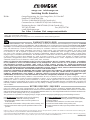
Standard I/O connections for a 4-conductor cable or PTO2-10 6-pin connector on an LDI linear sensor are shown below
Please note that your LDI sensor was calibrated at the factory to a specified measuring range. You may choose to retain this calibration if it suits your purpose,
or you may choose to recalibrate your sensor using the Field Programmability feature if you desire a more precise match of the sensor’s electrical output to your
mechanical device’s range of movement.
Omega’s LDI Linear Position Sensors Field Programmability feature allows the installer to very simply and quickly match the full scale electrical output of the
sensor to the actual mechanical range of movement of the device in which the sensor is installed. This type of activity is usually referred to as field calibration.
To proceed with the field calibration, follow these instructions:
1. Install the sensor into your mechanical device, leaving the sensor’s I/O unconnected.
2. Connect the black wire or common ground pin to power ground (-), and then connect the correct DC power input (+) to the sensor via the red wire or
power (+) pin.
3. To begin the Field Programmability process for voltage output, connect a DC voltmeter having the appropriate range(10 Volts) with its plus (+) test lead
connected to the green wire or analog output pin, and the meter's (-) test lead connected to the black wire or common ground pin.
4. To begin the Field Programmability process for current loop output, connect a DC milliammeter having an appropriate range with its plus (+) test lead
connected to the green wire or analog output pin and its minus (-) test lead connected to one end of the loop load resistor, typically 250 or 500 Ohms.
Connect the other end of the loop load resistor to the black wire or common ground pin.
5. Extend your mechanical device to its full range of motion, then connect the white (cal) wire or cal pin to the black wire or common ground pin for 2-3
seconds.
6. Fully retract the mechanical device to its zero or start position, then connect the white (cal) wire or cal pin to the black wire or common ground pin for
2-3 seconds.
7. The sensor’s output is now calibrated to the end points of your mechanical device's range of motion. The Field Programmability procedure can be
redone without limit, but its operational range is limited to 20% of specified full range, both at zero and at full range. (0 to 20% around zero, and 80 to
100% around full range) Note that both ends of the sensor’s range must be calibrated using the Field Programmability procedure for the process to
take effect.
8. When the Field Programmability process is completed, disconnect the voltmeter, or, in the case of current loop output, disconnect the milliammeter
and reconnect the loop load to the green wire or analog output pin. If you are using a cable output sensor, you may wish to trim and insulate the end
of the white (cal) wire to avoid an inadvertent or accidental recalibration.
SHEET
Conductor Color or Connector Pin
Red or Pin E: + Power Input: 12-30 V DC
(min. 18 V DC for 4 - 20 mA
current output)
Black or Pin D: Common Ground
Green or Pin A: Analog DC Output: 0 -10 V
or 4 - 20 mA
White or Pin B: Field Programmability (cal)
NOTE: The 4-20 mA DC output is 3-wire sourcing,
Do not connect to 2-wire loop-powered system

omega.com info@omega.com
Servicing North America:
U.S.A.:
Omega Engineering, Inc., One Omega Drive, P.O. Box 4047
Stamford, CT 06907-0047 USA
Toll-Free: 1-800-826-6342 (USA & Canada only)
Customer Service: 1-800-622-2378 (USA & Canada only)
Engineering Service: 1-800-872-9436 (USA & Canada only)
Tel: (203) 359-1660 Fax: (203) 359-7700
e-mail: [email protected]
For Other Locations Visit omega.com/worldwide
The information contained in this document is believed to be correct, but OMEGA accepts no liability for any errors it contains, and reserves the
right to alter specifications without notice.
WARNING:
These products are not designed for use in, and should not be used for, human applications.
WARRANTY/DISCLAIMER
OMEGA ENGINEERING, INC. warrants this unit to be free of defects in materials and workmanship for a period of
13 months
from date of purchase. OMEGA’s WARRANTY adds an additional one (1) month grace period to the normal
one (1) year product
warranty
to cover handling and shipping time. This ensures that OMEGA’s customers receive maximum coverage on each product.
If the unit malfunctions, it must be returned to the factory for evaluation. OMEGA’s Customer Service Department will issue an
Authorized Return (AR) number immediately upon phone or written request. Upon examination by OMEGA, if the unit is found
to be defective, it will be repaired or replaced at no charge. OMEGA’s WARRANTY does not apply to defects resulting from
any action of the purchaser, including but not limited to mishandling, improper interfacing, operation outside of design limits,
improper repair, or unauthorized modification. This WARRANTY is VOID if the unit shows evidence of having been tampered with
or shows evidence of having been damaged as a result of excessive corrosion; or current, heat, moisture or vibration; improper
specification; misapplication; misuse or other operating conditions outside of OMEGA’s control. Components in which wear is not
warranted, include but are not limited to contact points, fuses, and triacs.
OMEGA is pleased to offer suggestions on the use of its various products. However, OMEGA neither assumes
responsibility
for any omissions or errors nor assumes liability for any damages that result from the use of its
products in accordance
with information provided by OMEGA, either verbal or written. OMEGA warrants only
that the parts manufactured
by the company will be as specified and free of defects. OMEGA MAKES NO OTHER
WARRANTIES OR REPRESENTATIONS
OF ANY KIND WHATSOEVER, EXPRESSED OR IMPLIED, EXCEPT THAT OF
TITLE, AND ALL IMPLIED WARRANTIES
INCLUDING ANY WARRANTY OF MERCHANTABILITY AND FITNESS FOR A
PARTICULAR PURPOSE ARE HEREBY DISCLAIMED. LIMITATION OF LIABILITY: The remedies of purchaser set forth
herein are exclusive, and the total liability of OMEGA with respect to this order, whether based on contract, warranty,
negligence, indemnification, strict liability or otherwise, shall not exceed the purchase price of the component upon
which liability is based. In no event shall OMEGA be liable for consequential, incidental or special damages.
CONDITIONS: Equipment sold by OMEGA is not intended to be used, nor shall it be used: (1) as a “Basic Component” under 10
CFR 21 (NRC), used in or with any nuclear installation or activity; or (2) in medical applications or used on humans. Should any
Product(s) be used in or with any nuclear installation or activity, medical application, used on humans, or misused in any way,
OMEGA assumes no responsibility as set forth in our basic WARRANTY / DISCLAIMER language, and, additionally, purchaser will
indemnify OMEGA and hold OMEGA harmless from any liability or damage whatsoever arising out of the use of the Product(s) in
such a manner.
RETURN REQUESTS / INQUIRIES
Direct all warranty and repair requests/inquiries to the OMEGA Customer Service Department. BEFORE RETURNING ANY
PRODUCT(S) TO OMEGA, PURCHASER MUST OBTAIN AN AUTHORIZED RETURN (AR) NUMBER FROM OMEGA’S CUSTOMER
SERVICE DEPARTMENT (IN ORDER TO AVOID PROCESSING DELAYS). The assigned AR number should then be marked on the
outside of the return package and on any correspondence.
The purchaser is responsible for shipping charges, freight, insurance and proper packaging to prevent breakage in transit.
FOR
WARRANTY
RETURNS, please have the following
information available BEFORE contacting OMEGA:
1.
Purchase Order number under which the product was
PURCHASED,
2.
Model and serial number of the product under warranty, and
3.
Repair instructions and/or specific problems relative to the
product.
FOR
NON-WARRANTY
REPAIRS, consult OMEGA for current
repair charges. Have the following information available BEFORE
contacting OMEGA:
1.
Purchase Order number to cover the COST of the repair,
2.
Model and serial number of the product, and
3.
Repair instructions and/or specific problems relative to the
product.
OMEGA’s policy is to make running changes, not model changes, whenever an improvement is possible. This affords our customers the latest in technology and
engineering. OMEGA is a registered trademark of OMEGA ENGINEERING, INC.
© Copyright 2013 OMEGA ENGINEERING, INC. All rights reserved. This document may not be copied, photocopied, reproduced, translated, or reduced to any electronic
medium or machine-readable form, in whole or in part, without the prior written consent of OMEGA ENGINEERING, INC.
M0000/0013
-
 1
1
-
 2
2


Omega LDI Series Owner's manual
- Category
- Motorcycle Accessories
- Type
- Owner's manual
Ask a question and I''ll find the answer in the document
Finding information in a document is now easier with AI
Related papers
-
Omega DRG-SC-TC Owner's manual
-
-
-
-
-
-
-
-
-