Whirlpool 3LWTW4800YQ User guide
- Category
- Washing machines
- Type
- User guide

WASHER INSTALLATION INSTRUCTIONS
INSTRUCTIONS POUR L’INSTALLATION DU LAVE-LINGE
INSTRUCCIONES DE INSTALACIÓN DE LA LAVADORA
Table of Contents
Table des matiéres
WASHER SAFETY ..............................................................2
INSTALLATION REQUIREMENTS ..................................... 2
Tools and Parts .....................................................................2
Specications ....................................................................... 3
Location Requirements .......................................................3
Drain System ........................................................................ 4
Electrical Requirements ......................................................5
SECURITE DU LAVE-LINGE ............................................11
EXIGENCES D’INSTALLATION .......................................12
Outillage et pièces ............................................................... 12
Caractéristiques ................................................................... 13
Exigences d’emplacement ................................................. 13
Système de vidange ............................................................. 13
Spécications électriques ................................................... 14
Índice
SEGURIDAD DE LA LAVADORA ..................................... 22
REQUISITOS DE INSTALACIÓN .....................................23
Herramientas y piezas ....................................................... 23
Especicationes ................................................................. 24
Requisitos de ubicación .................................................... 24
Sistema de desagüe ........................................................... 25
Requisitos eléctricos ......................................................... 26
INSTALLATION INSTRUCTIONS ...................................... 5
Connect Drain Hose ............................................................. 6
Connect Inlet Hoses ............................................................. 7
Level Washer ........................................................................ 8
Power Cord Installation ...................................................... 9
Complete Installation Checklist .......................................... 9
STORAGE AND MOVING CARE .................................... 10
INSTRUCTIONS D’INSTALLATION ................................. 15
Raccordement du tuyau de vidange ........................................16
Raccordement des tuyaux d’arrivée d’eau ........................ 17
Établissement de l’aplomb du lave-linge ........................... 18
Installation du cordon d’alimentation.................................19
Liste de vérication pour l’achèvement de l’installation
..... 20
PRÉCAUTIONS À PRENDRE EN CAS
D’ENTREPOSAGE OU DE DÉMÉNAGEMENT .............. 21
INSTRUCCIONES DE INSTALACIÓN .............................26
Conexión de la manguera de desagüe ............................. 27
Conexin de las mangueras de entrada ............................ 28
Nivelación de la lavadora .................................................. 29
Instalación del cable eléctrico .......................................... 30
Complete la instalación ..................................................... 31
ALMACENAMIENTO Y CUIDADO
DURANTE EL TRASLADO .............................................. 32
3LWTW4740
3LWTW4800
3LMVWC400
Ceci est une traduction de l’anglais.
This is the original language (English)
Traducido del inglés.
W10592554A - EN/FR/SP/AR
W10592555A - PT/GR/IT/DE
3LWTW5550
3LWTW4840
3LMVWC100

2
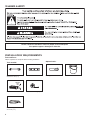
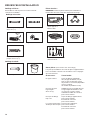
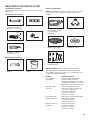
Optional tools:
INSTALLATION REQUIREMENTS
Tools and Parts:
Gather required tools and parts before starting installation.
102 mm
min
(4")
Wood block
Adjustable or open end
wrench 14 mm (
9
/
16
")
Ruler or measuring tape
Level
Pliers that open to
44.5 mm (1
3
⁄
4
")
Flashlight Bucket
Tools needed:
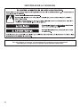
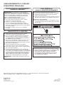
WASHER SAFETY
Please contact the machine's owner for proper service and repairs
if the product appears damaged or defective.

3
Technical Specications:
220–240 V ~50 Hz. AC, 1ph 650 Watts, IP24
Parts supplied:
NOTE: All parts supplied for installation are in the
cardboard insert in the top of the washer.
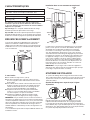
LOCATION REQUIREMENTS
Select proper location for your washer to improve performance
and minimize noise and possible “washer walk”. Install your
washer in a basement, laundry room, closet, or recessed area.
1067 mm
(42")
686 mm
(27")
699 mm
(27
1
/2")
Alternate parts: (Not supplied with washer)
Your installation may require additional parts. To order, please
contact the dealer from whom you purchased your washer or
an authorized service company.
If you have: You will need:
Overhead sewer Standard 76 L (20 gal.) 990 mm (39")
tall drain tub or utility sink, sump
pump and connectors (available
from local plumbing suppliers)
25 mm (1") standpipe 51 mm (2") diameter to 25 mm (1")
diameter Standpipe Adapter
Part Number 3363920
Connector Kit Part Number 285835
Drain hose too short Extension Drain Hose Part
Number 285863
Connector Kit Part Number 285835
Lint clogged drain Drain Protector Part Number 367031
Connector Kit Part Number 285835
Drain hose with clamp,
form, and cable tie
Inlet hoses
“Y” connector
Rubber washer
Dry Linen Capacity IEC Capacity
These units are sold in multiple regions with different
requirements for measuring capacity. Below are a few
of the valid forms of measure posted on this product:
Dry Linen Capacity: A weight measure that reects a maximum
load size that can be loaded into the washer.
IEC Capacity: The capacity measure that represents the
maximum capacity of dry linens and textiles which the
manufacturer declares can be treated in a specic cycle.
10,5 kg (23 lb) 7,5 kg (16,5 lb)
SPECIFICATIONS
Plugs and cord lock cover
You will need:
n
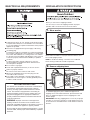
A water heater set to 49° C (120° F).
n
An earthed electrical outlet located within 1,2 m (4 ft) of power
cord on back of washer.
n
Hot and cold water faucets located within 0,9 m (3 ft) of hot
and cold water ll valves on washer, and water pressure
of 20-100 psi (138-690 kPa).
n
A level oor with maximum slope of 25 mm (1") under entire
washer. Installing on carpet is not recommended.
n
Floor must support washer’s total weight (with water and load)
of 143 kgs (315 lbs).
IMPORTANT: Do not install, store, or operate washer where it will
be exposed to weather or in temperatures below 0° C (32° F).
Water remaining in washer after use may cause damage in low
temperatures. See “Washer Care” in your Use and Care Guide
for winterizing information.
Proper installation is your responsibility.

4
Laundry tub drain system
Minimum capacity: 76 L (20 gal.) Top of laundry tub must be at
least 990 mm (39") above oor; install no higher than 1.22 m (48")
from bottom of washer.
IMPORTANT: To avoid siphoning, no more than 114 mm (4.5") of
drain hose should be inside standpipe or below the top of wash
tub. Secure drain hose with cable tie.
990 mm
(39")
114 mm
(4.5")
Floor drain system
Floor drain system requires a Siphon Break Kit (Part Number
285834), 2 Connector Kits (Part Number 285385), and an
Extension Drain Hose (Part Number 285863) that may be
purchased separately. To order, please contact the dealer from
whom you purchased your washer or an authorized service
company. Minimum siphon break: 710 mm (28") from bottom
of washer. (Additional hoses may be needed.)
DRAIN SYSTEM
Drain system can be installed using a oor drain, wall standpipe,
oor standpipe, or laundry tub. Select method you need.
Minimum diameter for a standpipe drain: 51 mm (2"). Minimum
carry-away capacity: 64 L (17 gal.) per minute. Top of standpipe
must be at least 990 mm (39") high; install no higher than
1.22 m (48") from bottom of washer. If you must install higher
than 1.22 m (48"), you will need a sump pump system.
Wall standpipe drain system
Floor standpipe drain system
114 mm
(4.5")
990 mm
(39")
114 mm
(4.5")
See requirements for “Floor standpipe drain system.”
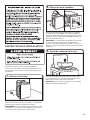
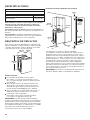
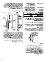
Recessed area or closet installation
Dimensions show recommended spacing allowed, except for
closet door ventilation openings which are minimum required.
This washer has been tested for installation with spacing of
0 mm (0") clearance on the sides. Consider allowing more space
for ease of installation and servicing, and spacing for companion
appliances and clearances for walls, doors, and oor moldings.
Add spacing of 25 mm (1") on all sides of washer to reduce
noise transfer. If a closet door or louvered door is installed, top
and bottom air openings in door are required.
IMPORTANT: Washers that feature ventilation openings in the
base of the unit must not be obstructed by carpet.
76 mm
(3")
76 mm
(3")
155 cm
2
(24 in.
2
)
310 cm
2
(48 in.
2
)
432 mm
(17")
25 mm
(1")
126 mm
(5")
356 mm
(14" max.)
25 mm
(1")

5
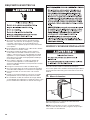
ELECTRICAL REQUIREMENTS
EARTHING INSTRUCTIONS
This washer must be earthed. In the event of a malfunction
or breakdown, earthing will reduce the risk of electric
shock by providing a path of least resistance for electric
current. This washer is equipped with a cord having an
equipment-earthing conductor and an earthing plug. The
plug must be plugged into an appropriate outlet that is
properly installed and earthed in accordance with all local
codes and ordinances.
WARNING: Improper connection of the equipment-
earthing conductor can result in a risk of electric shock.
Check with a qualified electrician or serviceman if you are in
doubt as to whether the appliance is properly earthed.
Do not modify the plug provided with the appliance – if it will
not fit the outlet, have a proper outlet installed by a qualified
electrician.
n
A 220-240 volt, 50 Hz., AC only, 10-amp, fused electrical supply
is required. A time-delay fuse or circuit breaker is recommended.
It is recommended that a separate circuit breaker serving only this
appliance be provided.
n
This washer is equipped with a power supply cord having
an earthing plug.
n
To minimize possible shock hazard, the cord must be plugged
into a mating, earthing-type outlet, earthed in accordance with
local codes and ordinances. If a mating outlet is not available,
it is the personal responsibility and obligation of the customer
to have the properly earthed outlet installed by a qualied
electrician.
n
If codes permit and a separate earth wire is used, it is
recommended that a qualied electrician determine that
the earth path is adequate.
n
Do not earth to a gas pipe.
n
Check with a qualied electrician if you are not sure the
washer is properly earthed.
n
Do not have a fuse in the neutral or earth circuit.
n When in the installed position, the mains plug must be
accessible for disconnection.
n If the supply cord is damaged, it must be replaced by the
manufacturer, its service agent, or similarly qualied persons
in order to avoid a hazard.
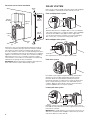
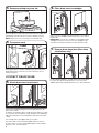
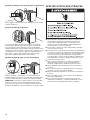
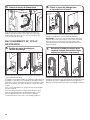
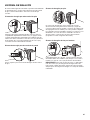
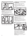
INSTALLATION INSTRUCTIONS
Before you start: remove shipping materials
It is necessary to remove all shipping materials for proper
operation and to avoid excessive noise from washer.
Move washer to within 1.2 m (4 ft) of its nal location; it must
be in a fully upright position.
NOTE: To avoid oor damage, set washer onto cardboard
before moving it and make sure lid is taped shut.
To avoid damaging oor, place cardboard supports from
shipping carton on oor behind washer. Tip washer back and
place on cardboard supports. Remove shipping base. Set
washer upright.
IMPORTANT: Removing shipping base is necessary for proper
operation. If your washer includes a sound shield, please refer
to the instructions included with the sound shield to install it at
this time.
1. Move washer
2. Remove shipping base

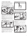
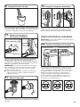
6
For oor drain installations, you will need to remove the drain
hose form from the end of the drain hose. You may need
additional parts with separate directions. See “Tools and Parts”.
7. Remove drain hose form (oor drain
installations only)
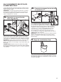
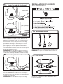
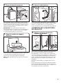
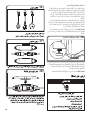
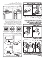
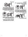
CONNECT DRAIN HOSE
Remove the red plastic plug from the black drain port on the
back of the washer.
If clamp is not already in place on elbow end of drain hose, slide
it over end as shown. Squeeze clamp with pliers and slide black
elbow end of drain hose onto black drain port and secure with
clamp.
For a laundry tub or standpipe drain, go to step 6.
For a oor drain, remove the preinstalled drain hose form as
shown in Step 7. You may need additional parts with separate
directions. See “Tools and Parts”.
5. Attach drain hose to drain port
Place hose into standpipe (shown in picture) or over side of
laundry tub.
IMPORTANT: 114 mm (4.5") of drain hose should be inside
standpipe; do not force excess hose into standpipe or lay
on bottom of laundry tub. Drain hose form must be used.
6. Place drain hose in standpipe
114 mm
(4.5")
Drain
hose form
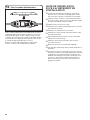
Remove tape from washer lid, open lid and remove cardboard
packing tray from tub. Be sure to remove all parts from tray.
NOTE: Keep tray in case you need to move washer later.
Firmly grasp power cord plug and pull to free from rear panel.
Gently place power cord over console to allow free access
to back of washer.
3. Remove packing tray from tub
4. Free power cord

7
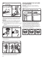
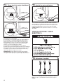
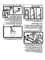
CONNECT INLET HOSES
Washer must be connected to water faucets with new inlet
hoses with at washers (provided). Do not use old hoses.
NOTE: Both hoses must be attached and have water owing
to inlet valves. If you are only connecting to a cold water
faucet, you must use a Y-adapter (provided) .
Attach hose to hot water faucet. Screw on coupling by hand
until it is seated on washer. Use pliers to tighten couplings an
additional two-thirds turn. Repeat this step with second hose
for cold water faucet.
IMPORTANT: Do not overtighten or use tape or sealants on
valve when attaching to faucets or washer. Damage can result.
HELPFUL HINT: Make note of which hose is connected to
hot water to help in attaching hoses to washer correctly. In
most standard congurations, hoses will cross over each other
when attached correctly.
8a. Connect inlet hoses to
water faucets
Run water for a few seconds through hoses into a laundry tub,
drainpipe, or bucket to prevent clogs. Water should run until clear.
9. Clear water lines
Attach the brass female end of the “Y” connector to the cold
water faucet. Use pliers to tighten couplings an additional
two-thirds turn. One end of the long hose has a wire mesh
strainer inside the coupling. Attach this end to the “Y”
connector. Attach washer cold inlet hose to other side of
“Y” connector. Screw on coupling by hand until it is seated
on connector. Using pliers, tighten the couplings an additional
two-thirds turn.
IMPORTANT: Do not overtighten or use tape or sealants
on valve when attaching to faucets or washer. Damage
can result.
8b.
Connect inlet hoses to
“Y” connector
Attach hot water hose to hot water inlet valve marked with
a red ring. Screw coupling by hand until it is snug. Use pliers
to tighten couplings an additional two-thirds turn. Repeat with
cold water inlet valve.
IMPORTANT: To reduce risk of hose failure, replace the hoses
every 5 years. Record hose installation or replacement dates
for future reference.
n
Periodically inspect and replace hoses if bulges, kinks, cuts,
wear, or leaks are found.
10. Connect inlet hoses to washer
Turn on water faucets to check for leaks. A small amount of
water may enter washer. It will drain later.
11. Check for leaks

8
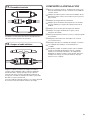
Secure drain hose to laundry tub leg, drain standpipe, or inlet
hoses for wall standpipe with cable tie.
12. Secure drain hose
4.5
114 mm"
(4.5")
(4.5")
114 mm
4.5"
(113 mm)
(4.5")
114 mm
Laundry Tub Standpipe Wall
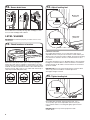
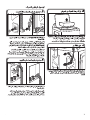
LEVEL WASHER
IMPORTANT: Level washer properly to reduce excess noise
and vibration.
With washer in its nal location, place a level on top edges of
washer. Use side seam as a guide to check levelness of sides.
Check levelness of front using lid, as shown. Rock washer back
and forth to make sure all four feet make solid contact with oor.
If washer is level, skip to step 15, (on models with metal feet) or
step 16 (on models with plastic feet).
13. Check levelness of washer
Place level here
Place level here
Not Level LEVEL Not Level
If washer is not level:
On models with metal feet, use a 14 mm (9/16") open-end or
adjustable wrench to turn jam nuts clockwise on feet until they are
about 13 mm (1/2") from the washer cabinet. Then turn the leveling
foot clockwise to lower the washer or counterclockwise to raise
the washer.
On models with plastic feet, use adjustable pliers to turn the plastic
leveling foot counterclockwise to lower the washer or clockwise to
raise the washer. On all models, recheck levelness of washer and
repeat as needed.
HELPFUL TIP: You may want to prop up front of washer about
102 mm (4") with a wood block or similar object that
will support weight of washer.
On models with metal feet, when washer is level, use a
14 mm (9/16") open-end or adjustable wrench to turn jam
nuts counterclockwise on leveling feet tightly against washer
cabinet.
HELPFUL TIP: You may want to prop washer with
wooden block.
15. Tighten leveling feet
Jam nut
14.
Adjust leveling feet
Jam nut
Models with
metal feet
or
Models with
plastic feet

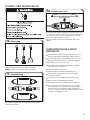
9
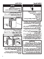
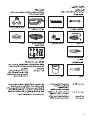
Select the plug that ts with the electric receptacle.
NOTE: Plug types and quantities will vary by model.
16. Select plug
POWER CORD INSTALLATION
Assemble the plug into the end of the power cord located on
the back of the washer.
17. Assemble plug
COMPLETE INSTALLATION
CHECKLIST
q
Check electrical requirements. Be sure you have correct
electrical supply and recommended earthing method.
q
Check that all parts are now installed. If there is an extra
part, go back through steps to see what was skipped.
q
Check that you have all of your tools.
q
Check that yellow shipping materials were completely
removed from back of washer.
q
Check that water faucets are on.
q
Check for leaks around faucets and inlet hoses.
q
Remove protective lm from console and any tape
remaining on washer.
q
Check that washer is plugged into an earthed outlet.
q
Dispose of/recycle all packaging materials.
q
Read “Washer Use” in your Washer User Instructions.
q
To test and clean your washer, measure 1/2 of normal
recommended amount of powdered or liquid detergent
and pour it into washer basket or detergent dispenser
(on some models). Close lid. Select any cycle. Start washer
and allow to complete full cycle.
Secure the power cord by seating the connection on the cord
lock. Place the cord lock cover and push until it snaps. Make
sure the power cord connection is seated on the cord lock
and that the cord lock clamps correctly.
Plug power supply cord into an earthed outlet. Turn power
supply on.
18. Secure power cord

10
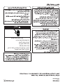
STORAGE AND MOVING CARE
REINSTALLING/USING WASHER AGAIN
To reinstall washer after non-use, vacation, winter storage,
or moving:
1. Refer to Installation Instructions to locate, level, and
connect washer.
2. Before using again, run washer through the following
recommended procedure:
To use washer again:
1. Flush water pipes and hoses. Reconnect water inlet
hoses. Turn on both water faucets.
2. Plug in washer or reconnect power.
3. Run washer through BULKY ITEMS cycle to clean
washer and remove antifreeze, if used. Use only HE
High Efciency detergent. Use half the manufacturer’s
recommended amount for a medium-size load.
TRANSPORTING YOUR WASHER
WINTER STORAGE CARE
IMPORTANT: To avoid damage, install and store washer
where it will not freeze. Because some water may stay in
hoses, freezing can damage washer. If storing or moving
during freezing weather, winterize your washer.
To winterize washer:
1. Shut off both water faucets; disconnect and drain water
inlet hoses.
2. Put 1 L (1 qt) of R.V.-type antifreeze in basket and run
washer on RINSE & SPIN cycle for about 30 seconds to
mix antifreeze and remaining water.
3. Unplug washer or disconnect power.
1. Shut off both water faucets. Disconnect and drain water
inlet hoses.
2. If washer will be moved during freezing weather, follow
WINTER STORAGE CARE directions before moving.
3. Disconnect drain from drain system and drain any
remaining water into a pan or bucket. Disconnect drain
hose from back of washer.
4. Unplug power cord.
5. Place inlet hoses and drain hose inside washer basket.
6. Drape power cord over edge and into washer basket.
7. Place packing tray from original shipping materials back
inside washer. If you do not have packing tray, place
heavy blankets or towels into basket opening. Close lid
and place tape over lid and down front of washer. Keep
lid taped until washer is placed in new location.
IMPORTANT: Washer must be transported in the upright
position.
EU representative: Whirlpool Europe s.r.l., Viale Guido Borghi 27, 21025 Comerio (VA) Italy
Manufacturer: Whirlpool Corp., 119 Birdseye St., Clyde, OH 43410
Page is loading ...
Page is loading ...
Page is loading ...
Page is loading ...
Page is loading ...
Page is loading ...
Page is loading ...
Page is loading ...
Page is loading ...
Page is loading ...
Page is loading ...
Page is loading ...
Page is loading ...
Page is loading ...
Page is loading ...
Page is loading ...
Page is loading ...
Page is loading ...
Page is loading ...
Page is loading ...
Page is loading ...
Page is loading ...
Page is loading ...
Page is loading ...
Page is loading ...
Page is loading ...
Page is loading ...

6
4.5"
(114 mm)
Drain
hose form
7
Page is loading ...
Page is loading ...
Page is loading ...
Page is loading ...
Page is loading ...

2
2
2
3
4
5
5
5
6
7
8
9
10
EN/FR/SP/AR - W10592554A PT/
GR/IT/DE - W10592555A
3LWTW4740
3LWTW4800
3LMVWC400
3LWTW5550
3LWTW4840
3LMVWC100
-
 1
1
-
 2
2
-
 3
3
-
 4
4
-
 5
5
-
 6
6
-
 7
7
-
 8
8
-
 9
9
-
 10
10
-
 11
11
-
 12
12
-
 13
13
-
 14
14
-
 15
15
-
 16
16
-
 17
17
-
 18
18
-
 19
19
-
 20
20
-
 21
21
-
 22
22
-
 23
23
-
 24
24
-
 25
25
-
 26
26
-
 27
27
-
 28
28
-
 29
29
-
 30
30
-
 31
31
-
 32
32
-
 33
33
-
 34
34
-
 35
35
-
 36
36
-
 37
37
-
 38
38
-
 39
39
-
 40
40
-
 41
41
-
 42
42
-
 43
43
-
 44
44


Whirlpool 3LWTW4800YQ User guide
- Category
- Washing machines
- Type
- User guide
Ask a question and I''ll find the answer in the document
Finding information in a document is now easier with AI
in other languages
- français: Whirlpool 3LWTW4800YQ Mode d'emploi
- español: Whirlpool 3LWTW4800YQ Guía del usuario
Related papers
-
Whirlpool 4GNTW4600YQ2 User manual
-
Whirlpool 7MWTW1950EW1 Installation guide
-
-
-
Whirlpool W10044800 User manual
-
-
-
-
Amana NTW4516FW Installation guide
-
Other documents
-
Maytag MHN30PDBGW Installation Instructions Manual
-
-
-
Maytag MVWC465HW Installation guide
-
-
-
-
-
-
Sears 2644432K Owner's manual