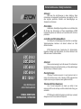
Eton ECC 1200.1 Installation & Operation Manual
- Category
- Car audio amplifiers
- Type
- Installation & Operation Manual
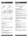
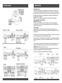
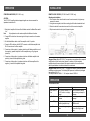
Eton ECC 1200.1 is a high-performance subwoofer amplifier, ideal for driving subwoofers with a power handling capacity of up to 1200 watts RMS. This powerful mono amplifier features a variable low-pass filter with a frequency range of 50-250 Hz, giving you precise control over the bass response of your subwoofer. Additionally, the ECC 1200.1 has a built-in subsonic filter, which helps to protect your subwoofer from damage by eliminating ultra-low frequencies that can be harmful to the speaker.
The ECC 1200.1 is also equipped with a remote bass boost control, which allows you to adjust the bass level from the driver's seat. This makes it easy to fine-tune the sound of your subwoofer to your liking, even while you're driving.


-
 1
1
-
 2
2
-
 3
3
-
 4
4
-
 5
5
-
 6
6
-
 7
7
-
 8
8
-
 9
9
-
 10
10
-
 11
11
-
 12
12


Eton ECC 1200.1 Installation & Operation Manual
- Category
- Car audio amplifiers
- Type
- Installation & Operation Manual
Eton ECC 1200.1 is a high-performance subwoofer amplifier, ideal for driving subwoofers with a power handling capacity of up to 1200 watts RMS. This powerful mono amplifier features a variable low-pass filter with a frequency range of 50-250 Hz, giving you precise control over the bass response of your subwoofer. Additionally, the ECC 1200.1 has a built-in subsonic filter, which helps to protect your subwoofer from damage by eliminating ultra-low frequencies that can be harmful to the speaker.
The ECC 1200.1 is also equipped with a remote bass boost control, which allows you to adjust the bass level from the driver's seat. This makes it easy to fine-tune the sound of your subwoofer to your liking, even while you're driving.
Ask a question and I''ll find the answer in the document
Finding information in a document is now easier with AI
in other languages
- Deutsch: Eton ECC 1200.1
Related papers
-
Eton CORE A2 User manual
-
-
-
-
-
-
-
Other documents
-
Audio Design V500.4 Owner's manual
-
Crossfire C3 102 Owner's manual
-
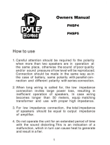 PYLE Audio 8 x PHSP4 User manual
-
MB QUART ZUR5.25IC Installation guide
-
Hifonics MERCURY IV Owner's manual
-
Crunch GTX 3000 D Owner's manual
-
-
Hifonics ZXi2201 Owner's manual
-
-
ARC Audio KS 1200.1 Owner's manual
