
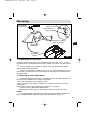
Betjenings- og installationsvejledning
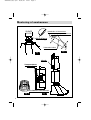
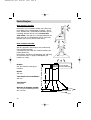
Emhætte for vægmontering
A
nvändarmanual
Köksfläkt med välvd dekor
Bruksveiledning
Buet kjøkkenvifte
User Guide
Curved Hood
99625951_ML_A.qxd 18/11/02 13:51 Page 1
Page is loading ...
Page is loading ...
Page is loading ...
Page is loading ...
Page is loading ...

DK
7
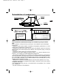
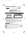
3. Montering af skorstensrøret
a) Med aftræk
Udledning af emskærmens aftræksluft skal foretages i henhold til de krav, andre berørte
myndigheder måtte have.
Aftræksrøret fra emskærmen må ikke tilsluttes en skorsten eller røgkanal, der er i brug.
Brugen af nedlagte røgkanaler skal godkendes af en autoriseret fagmand.
- Løsn luftlederen (fig. 6) og fjern den. Den skal kun bruges, når emskærmen monteres
med recirkulation.
- Tag skorstensrørets metalholder ud (fig. 3).
- Sæt kontraklapperne (fig. 2) i emhættens aftræksslange. Fjern tapen, der holder klap-
perne.
- Fastspænd skorstensrørets metalholder på væggen op mod loftet (fig. 3). Sørg for, at
de to trekantede indhak i metalholderen justeres korrekt i forhold til den lodrette streg
på væggen (hul med diameter 8, to skruer og rawlplugs medfølger).
- Sæt aftræksslangen med diameter 150 mm (
medfølger ikke
) i og fastgør den til
emskærmens aftræksstuds.
- Hvis slangens diameter kun er 125 mm, skal der anvendes et reduktionsstykke (fig. 4).
- Klargør skorstensrøret med åbningerne i siden nedad (fig. 5). Skub skorstensrørene ind
i hinanden.
- Fastspænd det øverste skorstensrør til metalholderen ved hjælp af de medfølgende
skruer. Udvid forsigtigt skorstensrøret en smule for at lette monteringen ved indføringen
bag metalholderen.
- Sænk det udvendige skorstensrør ned på emhætten.
Gode råd til installationen:
For at emskærmen skal fungere optimalt, anbefaler vi at tilslutte et aftræksrør-
/-slange med en diameter på 150 mm. Røret bør være så kort som muligt og
med så få bøjninger som muligt.
Montering af emskærmen
99625951_ML_A.qxd 18/11/02 13:51 Page 7
Page is loading ...
Page is loading ...
Page is loading ...
Page is loading ...
Page is loading ...
Page is loading ...
Page is loading ...
Page is loading ...
Page is loading ...

SE
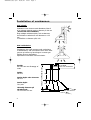
3. Montering av utsug för utomhusavledning:
a) Funktionssätt med utvädring till fria luften
Installationen skall efterfölja gällande reglementen för ventilering av lokaler.
Särskilt skall evakuerad luft inte ledas till en lufttrumma som samtidigt används för att
leda bort rök och os från apparater som går på gas eller andra bränslen.
Oanvända ventilationsgångar får inte tas i bruk förrän efter tillstånd av en kompetent
specialist.
- Ta bort de 2 fästskruvarna för deflektorn i plast (fig. 6).
Denna del används endast vid installation för sluten luftcirkulation .
- Ta ut fästplåten (fig. 3) för ventilationsgångarna.
- Sätt in backventilerna (fig. 2) i köksfläktens utvädringsledning. Ta av det självhäftan-
de bandet som håller fast backventilerna.
- Fäst metallstödet för ventilationsgångarna på väggen (fig. 3). Var noggrann med att
föra de två triangulära urtagen på
metallfästet i linje med den lodräta linjen på väggen (borrhål diam. 8 mm, 2 skruvar och
pluggar medföljer).
- Passa in ch fäst ventilationsgången på diameter 150 mm (
medföljer ej
) i köksfläktens
utgångsledning.
- I fall av ventilationsgång av diameter 125 mm använder man den medföljande adap-
tern (fig. 4).
- Gör i ordning den teleskopiska ventilationsgången och försök dölja gallren (fig. 5). För
in ledningarna, den ena i den andra så långt det går.
- Fäst det inre ventilationsgångens inre del på metallfästet med hjälp av medföljande
skruvar (för att underlätta monteringen för man lätt ut ventilationsgången för att kunna
föra in de två returerna bakom metallfästet).
- Justera längden på den teleskopiska ventilationsgången genom att föra ned den yttre
delen och passa in den i fläktens överdel.
Våra råd för installation:
för optimal användning av apparaten vill vi tillråda anslutning till en ventila-
tionsgång av diameter 150 mm. Försök minska antalet krökar och längden så
mycket som möjligt.
I fall köksfläkten fungerar med utvädring utomhus skall man försäkra sig om
att tillräckligt friskluftintag finns för att undvika undertryck i lokalen.
Hur du monterar din köksfläkt
17
99625951_ML_A.qxd 18/11/02 13:52 Page 17
Page is loading ...
Page is loading ...
Page is loading ...
Page is loading ...

22
I
nnhold
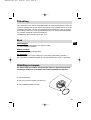
F
ra redaksjonen
Kjære kunde!
Vi takker deg for at du kjøpte denne kjøkkenviften fra BRANDT. Våre
forskere har utarbeidet en ny generasjon kjøkkenapparater som skal gjøre
matlaging til en glede.
Rene linjer og moderne estetikk gjør denne kjøkkenviften fra Brandt
til en naturlig del av ditt kjøkken hvor den skal bidra til å forene enkel
bruksmetode og høy prestasjon.
I denne serien fra Brandt finner du også et stort utvalg av kokeplater,
stekeovner, oppvaskmaskiner og kjøleskap som kan settes sammen med
denne kjøkkenviften fra Brandt.
Vår kundeservice er til din disposisjon både for å svare på spørsmål og
lytte til forslag. Du finner vår adresse på siste side i denne håndboken.
Brandt setter store krav til fornyelse. Vi legger vekt på at våre produkter
stadig gir større ytelse mens de samtidig er enkle i bruk og miljøvennlige,
at de holder estetiske mål og høye krav til solididitet.
Vennlig hilsen BRANDT.
Fra redaksjonen S.22
Oversikt over kjøkkenviften S.23
Sikkerhetsforskrifter S.23
Installasjon S.24
Montering S.25-28
Tilkobling S.29
Bruk S.29
Utskifting av lampen S.29
Rengjøring S.30
Kontakter S.31
I denne veiledningen viser,
til sikkerhetsforskrifter,
til gode råd og vink
99625951_ML_A.qxd 18/11/02 13:52 Page 22
Page is loading ...
Page is loading ...
Page is loading ...
Page is loading ...

NO
3. Montering av avtrekksrøret ved utendørs evakuering:
a) Funksjon med utendørs avtrekk
Installasjonen må være i overensstemmelse med gjeldende bestemmelser for ventilering av loka-
ler.
Særlig er det viktig at luften ikke evakueres gjennom et avtrekk som også brukes til uts-
lipp av røyk fra apparater som bruker gass eller annet brennstoff.
Dersom man tar i bruk kanaler igjen som ikke har vært i bruk på lang tid, må dette kun
skje etter godkjennelse fra en kompetent spesialist.
- Fjern de 2 festeskruene på plastdeflektoren (Fig. 6).
Denne delen brukes bare ved en installasjon med resirkulering.
Ta ut metallholderen til avtrekksrøret (Fig. 3).
- Sett på plass tilbakeslagsventilene (Fig. 2) i viftens uttaksrør. Fjern tapen fra klaffene.
- Fest avtrekksrørets metallholder på veggen (Fig. 3), med støtte i taket. Sørg for å stille
de 2 trekantede hakkene på metallholderen på linje med den vertikale streken på veg-
gen (bor med diameter 8, 2 vedlagte skruer og propper).
- Sett på plass, og fest avtrekkskanalen med diameter 150 mm (
leveres ikke med vif-
ten
) i viftens uttaksrør.
- Dersom kanalen har en diameter på 125 mm, bruk det vedlagte overgangsleddet (Fig.
4).
- Klargjør det teleskopiske avtrekksrøret. Luftspaltene skal skjules (Fig. 5). Sett det ene
røret maksimalt inn i det andre.
- Fest den øvre delen av det indre røret på metallholderen ved hjelp av de vedlagte
skruene (for å gjøre plasseringen lettere, skyv avtrekksrøret litt til side slik at du kan
plassere de to vinklene inn bak metallholderen).
- Juster lengden på det teleskopiske avtrekksrøret ved å trekke det ytre røret nedover,
og deretter sette det på plass på toppen av viften.
Våre installasjonsråd:
for at du skal få optimal nytte av apparatet, anbefaler vi deg å knytte det til en
kanal med en diameter på 150 mm. Antallet knekker og lengden på kanalen bør
begrenses så mye som mulig.
Dersom viften har et utendørs avtrekk, bør du sjekke at friskluftinntaket hele
tiden er stort nok for å unngå undertrykk i rommet.
Montering
27
99625951_ML_A.qxd 18/11/02 13:52 Page 27
Page is loading ...
Page is loading ...
Page is loading ...
Page is loading ...

32
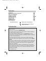
Contents
Introduction
Dear Customer,
Thank you for choosing the BRANDT hood.
Our design staff have produced a new generation of kitchen equipment,
to make everyday cooking a pleasure.
The modern, attractive design of your new Brandt hood will blend
smoothly into your kitchen installation, providing an optimum combination
of easy use and performance.
The Brandt range also includes a huge choice of fitted cooking hobs,
ovens, dish-washers and refrigerators, that will match your new Brandt
hood.
Of course, we make every effort to ensure that our products meet all your
requirements, and our Customer Service department is at your disposal,
to answer all your questions and to listen to all your suggestions (see
back cover of manual).
Brandt has always been a leader in the development of new products,
thus enhancing the quality of everyday life by providing increasingly effi-
cient products, that are easy to use, respect the environment, and are
attractive and reliable.
The BRANDT name.
Introduction P.32
Know the various parts of your hood P.33
Safety recommendations P.33
Installation conditions P.34
Installing your hood P.35-38
Connecting your hood P.39
Using your hood P.39
Changing a bulb P.39
Cleaning your hood P.40
How to contact us P.40
Throughout this manual,
indicates safety recommendations,
indicates advice to help you make the
best use of your duct
99625951_ML_A.qxd 18/11/02 13:52 Page 32

GB
Safety recommendations
K
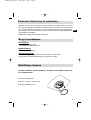
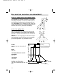
now the various parts of your hood ?
Fil
ter Cartridge
Control but
tons
(see below)
Light
123
Lighting 1 Low speed
Stop 2 Medium speed
Start 3 Max. speed
3-speed model
Silent electronic model
l Low speed
ll Medium speed
lll Max. speed
Lighting
33
Please become familiar with the safety recommendations, before installing and
using your hood.
This hood is designed for normal household use. This hood contains no asbestos.
- Do not allow naked flames to burn beneath the duct, i.e. do not cook " flambé " dishes
or allow a gas ring to burn with no pan placed on it (extracted flames could damage the duct).
- Frying under the duct should be constantly monitored.
- Repair work should only be carried out by an approved specialist.
- The metal filters should be regularly cleaned.
- The hood must not be installed or used over a fuel burning (wood, coal, etc.) stove.
To obtain optimum efficiency from your hood:
- You should preferably use the rear cooking rings on your cooker. We recommend that the
hood should be switched on from the beginning of the cooking and, in certain cases, may be
allowed to run for a few minutes after the end of the cooking.
Note :
- When a cooking hood is used simultaneously with other equipment burning gas or simi-
lar fuels, the room must be adequately ventilated.
When the duct is running at max. power, the air in a kitchen is entirely evacuated, and thus
replaced, in a few minutes.
IMPORTANT
- In the case of a kitchen heated by equipment connected to a chimney (e.g. a stove, etc.), the
hood must be installed in recycling mode .
- Do not use the hood without the metal filters.
99625951_ML_A.qxd 18/11/02 13:52 Page 33

34
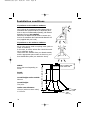
Installation conditions
If you have an air outlet to outdoors:
Your hood can be connected to this outlet through an
evacuation duct (enamel finished, in aluminium, flexi-
hose or other non-inflammable material), with internal
diameter 150 mm (
not supplied
).
Otherwise, an adapter may be used to connect your
hood to an evacuation duct with internal diameter 125
mm (supplied with your hood).
If you have no air outlet to outdoors:
All our units can be used in recycling mode (
with no
outlet to outdoors
).
In this case, an active carbon filter should be instal-
led, to eliminate smells .
These filters are available from your Brandt retailer,
and the appropriate part number is shown on your
duct identification plate (see inside the hood).
Width:
600 or 900 mm Depending on
model
Depth:
500 mm
Overall height under conduit:
280 mm
Overall height:
739 /1031
Outlet outer diameter:
150 mm (with non-return valve)
or 125 mm.
70 mm minimum for ventilation shaft
360 mm maximum without shaft
600 or 900
390
280
minimum 739 - maximum 1031
500
99625951_ML_A.qxd 18/11/02 13:52 Page 34

GB
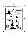
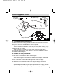
2. Installing the body of the hood:
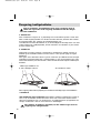
1. Pre-installation recommendations:
The distance between the cooking plane and the bottom of the hood must not be less
than 70 cm. If the instructions of the gas cooker installed under the hood specify a dis-
tance greater than 70 cm, then this distance must be respected.
Proceed as follows:
- Mark a vertical line on the wall, to ensure that your hood (and its chimney) are per-
fectly aligned with your cooker.
- Make a mark, on the vertical line, at least 70 cm above your cooking plane.
The vertical line and the mark at 70 cm will help you set up the installation as shown in
the attached installation diagram.
- Place the installation diagram supplied against the wall, and align the vertical line on
the wall with the " hood centreline " shown on the diagram.
- Drill four holes, dia. 8 mm, as shown on the diagram.
- Mount the two supports on the wall, using the four screws and plugs supplied with
the duct (fig. 1).
Remark: In the case of a hollow wall, use the appropriate screws and plugs.
- Mount the hood by locating its rectangular holes on the supports.
The width of the holes is sufficient to allow some margin for left/right adjustment.
IMPORTANT :
- Adjust the height and levelling using the support adjustment screws " A " (fig.1), and then
mount the hood firmly against the wall by tightening the screws " B " (fig. 1).
A (hex. head,
length: 8 mm)
B (Phillips head,
length: 25 mm)
Position of the 4 screws
and pegs provided
rectangular
holes
Foam seal in
place
Foam seal to
be glued on
Installing your hood
35
fig. 1
99625951_ML_A.qxd 18/11/02 13:52 Page 35

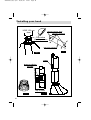
36
Installing your hood
fig. 2
fig. 4
fig. 3
fig. 5
HOSE 150 mm
diam
chimney mounting
T
op of hood
triangular notches
chimney support plate
Screw or clip for
carrying
Flap valv
es
(depending on model)
vents
99625951_ML_A.qxd 18/11/02 13:52 Page 36

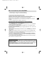
GB
3. Assembling the ventilation shaft for ducting outdoors:
a) Operation with evacuation to outdoors
The installation must comply with applicable regulations concerning room ventilation.
In particular, evacuated air must not be transferred through a conduit used to evacuate
fumes from equipment burning gas or similar fuels.
Unused and existing conduits can only be used following approval by a qualified specia-
list.
- Remove the two mounting screws from the plastic deflector (fig.6).
The plastic deflector is only used for an installation in recirculating mode .
- Recover the chimney support plate (fig.3).
- Push the non-return valves (fig.2) into the hood outlet pipe. Remove the adhesive
tape retaining the valves.
- Mount the metal chimney support on the wall, in contact with the ceiling (fig.3).
Check that the two triangular notches are aligned with the vertical line on the wall (drill
dia. 8 mm, two screws and plugs supplied).
- Engage and secure the evacuation duct, dia. 150 mm (
not supplied
) in the hood out-
let pipe.
- In the case of a duct, dia. 125 mm, use the adapter supplied (fig.4).
- Prepare your telescopic chimney, carefully covering the vents (fig.5).
Push the chimney sections, one into the other, as far as possible.
- Mount the upper part of the inner chimney on the metal support, using the screws
supplied (to facilitate installation, pull the chimney slightly clear, so that the two returns
can be inserted behind the metal support).
- Adjust the length of the chimney by sliding the outer part down and sitting it in the top
of the hood.
Installation recommendations:
For optimum use of your hood, we recommend that it be connected to a duct of
diameter 150 mm. Keep the number of angles and the duct length to a
minimum.
If your extractor hood is being used to dispel air outside, make sure your
kitchen has a fresh-air vent so that it does not become deprived of oxygen.
Installing your hood
37
99625951_ML_A.qxd 18/11/02 13:52 Page 37

4. Assembling the ventilation shaft for recirculating the air:
-
In this case, non-return valves are not required .
- Remove the two mounting screws from the plastic deflector (fig. 6).
- Mount the plastic fumes deflector against the wall, in contact with the ceiling (drill two
holes, dia. 8 mm, 200 mm apart, and use the screws and plugs supplied) (fig. 6).
Check that the deflector is central, in relation to the vertical line on the wall.
- Mount the evacuation duct (dia. 150 mm,
not supplied
) between the deflector and the
hood.
- Prepare your chimney, ensuring that the vents are towards the top and visible (fig. 7).
Push the chimney sections one into the other, as far as possible.
- Mount the upper part of the chimney on the plastic deflector, using the screws supplied
(to facilitate installation, pull the chimney slightly clear, so that the two returns can be
inserted behind the plastic deflector).
- Adjust the length of the chimney by sliding the outer part down and sitting it in the top
of the hood.
chimney mounting
Top of hood
position of screw
and plug
deflector
Screw or clip for carrying
Installing your hood
fig. 6
fig. 7
38
99625951_ML_A.qxd 18/11/02 13:52 Page 38

GB
Connecting your hood
Using your hood
Low speed:
- for simmering and dishes that create little steam,
- to create ventilation in the kitchen.
Medium speed:
- for normal cooking.
Maximum speed:
- for cooking creating considerable fumes or steam (frying, pressure cooker).
Reset medium power immediately maximum power is no longer required.
Changing a bulb
Before carrying out any work, switch off the hood either by unplugging the
power connector or by tripping the circuit breaker.
39
1.Remove the shade.
2. Replace with an G4-20W-12V bulb.
3. Replace the metal filters.
Your hood is supplied with a power cable H05VVF, with three wires, section 0.75mm² (neu-
tral + phase and earth). Your hood should be connected to a 230 V single phase mains
power supply, through a standard power socket CEI 83, which should remain accessible
following the installation of the finishing panels, or through an omni-polar cutout, with a
contact opening gap of at least 3 mm. If the power cable is damaged, contact an authori-
sed Brandt service agent.
Your installation should include a fuse, rating 10 A or 16 A.
99625951_ML_A.qxd 18/11/02 13:52 Page 39

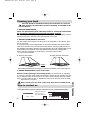
Handle
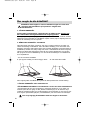
Cleaning your hood
The hood should be switched off before the metal filters are removed.
After cleaning, the metal filters should be installed, as described in the
instructions.
1. ROUTINE MAINTENANCE
Never use metal cleaning pads, abrasive products or excessively hard brushes.
Do
not clean the stainless steel using ammonia-based products.
To clean the outer casing and the lighting window, use only household cleaning products,
diluted in water, rinse with clean water and wipe with a soft cloth.
2. MONTHLY MAINTENANCE: metal filter
The filter retains greasy vapours and dust, and is very important for the efficient opera-
tion of your hood.
It can progressively become inflammable, as it becomes saturated with greasy residue.
Clean the metal filter using commercial household cleaner, rinse thoroughly and dry. In
the dishwasher, this cleaning should be done using the filter only, in the vertical position. Do not
clean the filter at the same time as the dirty dishes because of the risk of leaving stains.
Before using the metal filter for the first time, remove the protective film.
- To remove the metal filter:
1. Raise the filter handle. 2. Rotate the filter downwards.
After cleaning, install the filter by carrying out the above operations, in the reverse sequence.
3. ANNUAL MAINTENANCE: active carbon filter
ONLY for hoods operating in recirculating mode (not connected to an evacuation
to outdoors). This filter retains smells and should be changed at least annually, as a func-
tion of utilisation and to avoid any risk of fire. Filters may be obtained from your Brandt
dealer (see part number shown on identification plate, inside the hood). Note the instal-
lation date of a new filter.
Before carrying out any work on the hood, check that it is switched off.
In the spaces below, copy the reference numbers from your hood identification plate:
How to contact us
MADE IN FRANCE
230V ~ 50 Hz
BRANDT APPLIANCES SAS
7 rue Henri Becquerel
92500 RUEIL MALMAISON
40
99625951 11/02
99625951_ML_A.qxd 18/11/02 13:52 Page 40
-
 1
1
-
 2
2
-
 3
3
-
 4
4
-
 5
5
-
 6
6
-
 7
7
-
 8
8
-
 9
9
-
 10
10
-
 11
11
-
 12
12
-
 13
13
-
 14
14
-
 15
15
-
 16
16
-
 17
17
-
 18
18
-
 19
19
-
 20
20
-
 21
21
-
 22
22
-
 23
23
-
 24
24
-
 25
25
-
 26
26
-
 27
27
-
 28
28
-
 29
29
-
 30
30
-
 31
31
-
 32
32
-
 33
33
-
 34
34
-
 35
35
-
 36
36
-
 37
37
-
 38
38
-
 39
39
-
 40
40


Brandt AD249XN1 Owner's manual
- Category
- Cooker hoods
- Type
- Owner's manual
Ask a question and I''ll find the answer in the document
Finding information in a document is now easier with AI
in other languages
- dansk: Brandt AD249XN1 Brugervejledning
- svenska: Brandt AD249XN1 Bruksanvisning
Related papers
-
Groupe Brandt AD226WN1 Owner's manual
-
Brandt WTC0612A Owner's manual
-
Brandt AD289XT1 Owner's manual
-
Groupe Brandt AD236WN1 Owner's manual
-
-
Groupe Brandt AD389XT1 Owner's manual
-
-
-
-
Groupe Brandt AD1046B Owner's manual
Other documents
-
Eico Pisa 60 X User manual
-
De Dietrich HM8999E2 Owner's manual
-
Franke Cooker hood User manual
-
Thermex Harwich Lux Installation guide
-
-
-
-
-
KRAM 75335 User manual
-
 Franke Consumer Products FDF 9044 I XS ECS User manual
