Page is loading ...

INSTRUCTION MANUAL
MODEL 2002-32, 2002-33 AGILE TEST UPCONVERTER
Data, drawings, and other material contained herein are proprietary
to Cross Technologies, Inc., and may not be reproduced or
duplicated in any form without the prior permission of Cross
Technologies, Inc.
When ordering parts from Cross Technologies, Inc., be sure to
include the equipment model number, equipment serial number, and
a description of the part.
First Edition, November 2000 Rev 0
CROSS TECHNOLOGIES, INC.
6170 SHILOH ROAD
ALPHARETTA, GEORGIA 30005
(770) 886-8005
FAX (770) 886-7964
WEB www.crosstechnologies.com
E-MAIL [email protected]

INSTRUCTION MANUAL
MODEL 2002-32, 2002-33 AGILE TEST UPCONVERTER
TABLE OF CONTENTS PAGE
Warranty ....................................................2
1.0 General.........................................................3
1.1 Equipment Description.............................3
1.2 Technical Characteristics............................3
2.0 Installation ....................................................4
2.1 Mechanical ............................................4
2.2 Controls and Indicators...............................4
2.3 Input / Output Signals ..............................4
2.4 Accessing and Changing Jumpers............... 4
2.5 Installation / Operation ..............................5
2.5.1 Local Operation ..............................5
2.5.2 Frequency Setting, Frequency Mode....5
2.5.3 Low Side LO, 36 MHz Input..............5
2.5.4 Frequency Setting, Channel Mode.......7
2.5.5 Remote Operation ...........................8
2.5.6 Remote Control DOS Program...........8
3.0 Circuit Description..........................................9
3.1 Block Diagram Description ........................9
3.2 Controller Operation for 2002-32, -33..........9
3.2.1 General .......................................9
3.2.2 Frequency Setting, Frequency Mode.10
3.2.3 Frequency Setting, Channel Mode ...10
WARRANTY - The following warranty applies to all Cross Technologies, Inc. products.
All Cross Technologies, Inc. products are warranted against defective materials and workmanship for a
period of one year after shipment to customer. Cross Technologies, Inc.’s obligation under this warranty is
limited to repairing or, at Cross Technologies, Inc.’ option, replacing parts, subassemblies, or entire
assemblies. Cross Technologies, Inc. shall not be liable for any special, indirect, or consequential damages.
This warranty does not cover parts or equipment which have been subject to misuse, negligence, or accident
by the customer during use. All shipping costs for warranty repairs will be prepaid by the customer. There
are no other warranties, express or implied, except as stated herein.
CROSS TECHNOLOGIES, INC.
6170 SHILOH ROAD
ALPHARETTA, GEORGIA 30005
(770) 886-8005
FAX (770) 886-7964
WEB www.crosstechnologies.com
E-MAIL [email protected]
2002-32, -33 manual Page 2 11/29/00

MODEL 2002-32, 2002-33 AGILE TEST 199 - 319 MHz UPCONVERTER
SECTION 1 GENERAL
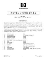
1.1 Equipment Description- The Model 2002-32,-33 Agile Test 199 - 319 MHz Upconverter takes a 36 MHz IF signal and
upconverts it to 199 - 319 MHz in 1.0 MHz steps. The IF carrier input is mixed with a synthesized 163 - 283 MHz local
oscillator signal. The output frequency is selected using up and down tune push button switches which command the
microprocessor to control the synthesized oscillator. A red LED lights when the PLL is unlocked and this alarm signal goes to an
open drain FET output. A yellow LED indicates remote operation. The output of the mixer is applied to the output amplifier
providing output levels of nominally -12dBm with -15 dBm in. The 2002-32
includes a wall power supply.The 2002-32R is
the rack mount version of the 2002-32 and the 2002-33R is the rack mount version of the 2002-33.
FIGURE 1.1 2002-32, -33 Agile Test Upconverter Block Diagram and Front Panel
LEVEL
199 -
319 MHz
CONTROLLER
163-283 MHz
36 MHZ INPUT
1. 3
IF LVL REM GAIN ALARM FREQUENCY (GHZ) TUNE
-25 -45 -65 UP DOWN
2003 TEST UPCONVERTER
CROSS TECHNOLOGIES, INC.
8 3
0. 3 1 2
0. 3 1 2
2002
1.2 Technical Characteristics
TABLE 1.0 2002-32,-33 UPCONVERTER SPECIFICATIONS
Characteristics Specifications*
Input Characteristics
Impedance 75 ohms unbalanced
Return Loss 15dB, minimum
Frequency 36 MHz center
Input Level -10 to -20 dBm
Input 1dB Compression +0 dBm
Input 3rd order Intercept +10 dBm
Output Characteristics
Impedance 50 ohms unbalanced
Return Loss 10dB, minimum
Frequency Band 199 - 319 MHz
Level -12 dBm with -15 dBm in
Channel Characteristics
Gain +3 dB ±2 dB
Spurious Response NA; output not filtered
Frequency Response ±2 dB, 199 - 319 MHz
±0.5 dB, any 10 MHz increment
Synthesizer Characteristics
Frequency Accuracy ± 10 kHz
Frequency Step 1.0 MHz minimum
Phase Noise Suitable for 64 kB/s QPSK with rate 1/2 FEC
Controls
Frequency Selection Push button switches with direct frequency readout
Output Level Potentiometer and Toggle switch
Indicators
PLL Alarm Red LED (with FET open drain )
Remote Yellow LED
Frequency Four digit displays show the desired output frequency in GHz
Other
DC Power, max. +15VDC, 300ma; -15VDC, 50ma; via wall power supply for 2002-32
RF, IF Connectors BNC, female
*Specifications subject to change without notice
2002-32, -33 manual Page 3 11/29/00

2.0 Installation
2.1 Mechanical - The 2002-32 and 2002-33 are packaged in an aluminum extrusion. The 2002-32R and 2002-33R are
mounted on a 1 3/4” X 19” panel that can be mounted to a rack using the 4 holes at the ends. The 2002-32 derives ± 15V from
the wall power supply and the 2003-33 derives ± 15V from the model 2000-01 power supply. See Figure 2.1.
IF LVL REM GAIN ALARM FREQUENCY (GHZ) TUNE
81. 3 3
2004 TEST UPCONVERTER
CROSS TECHNOLOGIES, INC.
-25 -45 -65 UP DOWN
FIGURE 2.1 SERIES 2000 ASSEMBLY DRAWING
EXTRUSION
BACKPLANE
REAR SCREWS (4EA)
FRONT SCREWS (4EA)
FRONT PANEL
RACK MOUNT PANEL (FOR -R MODELS ONLY)
PCB ASSEMBLY
WALL
POWER
SUPPLY
2.2 Controls and Indicators - Figure 2.2 shows front panel controls and indicators.
2.3 Input / Output Signals - Figure 2.3 shows the input and output signals to the 2002-32,-33.
2.4 Accessing and Changing On-Card Jumpers and Controls - Figure 2.4 shows jumpers (with factory settings)
and other on-card controls. To remove the printed circuit board (PCB) from the extrusion for access to the jumpers and controls:
1.) Remove four (4) rear panel screws (see Figure 2.1).
2.) Gently pull the backplane and PCB assembly completely out of the extrusion.
3.) With the power supply disconnected, move jumpers to the desired positions (Figure 2.4).
4.) To set Channel frequencies
apply power via power supply and program frequencies (see Section 2.5.4).
5.) Always remove power when installing the PCB in to the extrusion. Make sure the shield goes in the lower channel
and the PCB in the next channel above that in the extrusion.
6.) Gently push the backplane and PCB assembly completely in to the extrusion so the front panel controls go through
the front panel.
7.) Install four (4) rear panel screws.
2002-32, -33 manual Page 4 11/29/00

2.5 Installation / Operation -
2.5.1 Local Operation -
1.) If required, check that on-card jumpers are set to the desired positions (Figure 2.4)
2.) Connect the wall power supply to the 2002-32 and the wall power supply to 115 VAC, 60 Hz (Figure 2.1). For the
2033-33 be sure the ± 15 VDC inputs are connected to the 2000-01 Power Supply and the 2000-01 to 90-260 VAC, 47-
60 Hz.
3.) Connect a -15 dBm signal to IF In (Figure 2.1, Figure 2.3)
4.) Set the desired frequency by pushing SW3 or SW4. If numbers 0 to 9 appear when pushing SW3 or SW4, the
2002-32,-33 is set for the channel mode (with on-card jumper JP4, Figure 2.4). See section 2.5.2 for frequency
setting information.
5.) Be sure DS1 and DS6 are off (Figure 2.2).
6.) If needed, R52 can be adjusted (Figure 2.2) for input signals that are different than -15 dBm (-10 to -20 dBm). Note
that this adjusts the level of IF In and uncalibrates the 2002-32,-33 from its -15 dBm input setting
2.5.2 Frequency Setting, Frequency Mode - In this mode, the frequency is selected by pushing the up and down
switches (SW3, SW4) on the front panel until the desired frequency is indicated on the front on the display. The frequency
displayed is the desired output frequency with the IF center frequency input. EEROM U3 stores the last frequency set so in the
event of power failure the upconverter will go to the frequency it was set to prior to the power outage. The front panel frequency
setting switches increment or decrement the frequency in 1.0 MHz steps at approximately a 5 step per second rate. If the switch
remains depressed for approximately ten steps, the rate increases by a factor of ten. There is no muting of the output carrier
during frequency selection.
2.5.3 Low Side LO, 36 MHz Input - The 2002-32,-33 operates over it’s full 199 to 319 MHz range with low side LO and
36 MHz input. Also, note that there will be no spectrum inversion of the input IF modulation with the low side LO. The 2002-
32,-33 operates over it’s full 199 to 319 MHz range with low side LO and 36 MHz input as the following table shows.
TABLE 2.0 2002-32,-33 TEST UPCONVERTER FREQUENCY INFORMATION
TABLE 2.0 2002-32,-33 TEST UPCONVERTER FREQUENCY INFORMATION
TABLE 2.0 2002-32,-33 TEST UPCONVERTER FREQUENCY INFORMATION
TABLE 2.0 2002-32,-33 TEST UPCONVERTER FREQUENCY INFORMATION
LO-Side IF (MHz) LO Range (MHz) Output Frequency Range (MHz)
LOW 36 163-286 199-319
2002-32, -33 manual Page 5 11/29/00

0. 3
IF LVL REM ALARM FREQUENCY (GHZ) TUNE
2002 TEST UPCONVERTER
CROSS TECHNOLOGIES, INC.
1 2
UP DOWN
SW3 - UP Frequency
Control Pushbutton
Switch - When in
FREQUENCY mode (as set
by jumper JP2), when
pushed will increment
frequency in 1.0 MHz steps
at about a 0.2 second rate. If
held in for about 10 steps,
will increment frequency in
10 MHz steps at about a 0.2
second rate. When in
CHANNEL mode (as set by
jumper JP2), when pushed
momentarily will display the
channel number it’s on. If
held in will increment channel
number and when released
will display the frequency of
the selected channel.
FIGURE 2.2 2002-33 Front Panel Controls and Indicators
DS1 - Remote LED -
Lights yellow when
jumper JP3 is set to
REMOTE. When this
LED is on, SW3 and
SW4 on the front panel
are disabled and these
functions are controlled
remotely
DS2, DS3, DS4, DS5 -
Frequency Displays - Display the
desired output frequency which is
the Local Oscillator frequency
+36 MHz in GHz.
SW4 - DOWN Frequency
Control Pushbutton Switch -
Same as SW3 except decreases
frequency or channel
R52 - IF IN Level
Adjustment - Ten
turn potentiometer
that adjusts the level
of IF In. Set for +3dB
gain and can be
adjusted for --6 to
+6 dB gain
DS6 - Alarm LED -
Lights red when PLL
comes out of lock
IF IN RF OUT
J2
FIGURE 2.3 2002-32, -33 Inputs and Outputs
J4 - IF #1 Input - The
main IF 36 MHz input . This
is a 75Ω, BNC input at
normally -10 to -20 dBm
levels. The RF output of -12
dBm occurs with -15 dBm in
as set at the factory and this
gain can be adjusted by
front panel pot R52.
J2 - DC IN - The
+15 VDC AND -15
VDC regulated DC
voltage from the
wall power supply
-15 +15
GND
J6 - 1-2 GHZ RF OUT - The mixed LO + IF
RF output. This is an unfiltered output and will
also contain the LO, LO - IF, and other mixer
products. This is a 50Ω, BNC output at normally
-12 dBm level.
2002-32, -33 manual Page 6 11/29/00

2.5.4 Frequency Setting, Channel Mode - A second tuning mechanism is channel selection. This is accomplished when
the on board three-pin jumper (JP2) (Figure 2.4) is set to the “channel” position. Ten preset channels (0-9) can be selected as
follows:
1. The 2002-32,-33 PCB is removed from the extrusion (see section 2.4 for instructions) to access the channel selecting
decimal switch (SW5) and the push to program switch (SW2) (Figure 2.4). With the display mode jumper (JP2) set in
the frequency mode, the frequency set switches (SW3,SW4) are pushed to the frequency desired (Figure 2.2).
2. The decimal switch (SW5) is set to the channel number desired to be programmed (Figure 2.4).
3. Push programming button (SW2) to program the displayed frequency into that channel number (Figure 2.4).
4. The above steps are repeated for any additional channels that are desired to be programmed.
5. When finished, set JP2 (Figure 2.4) in the “Channel” position if this tuning mechanism is desired.
At the factory, channels zero through nine are programmed from 200 to 290 MHz in 10 MHz steps (0 = 200, 1 =210, 2 = 220,
etc.). When in the remote mode, either frequencies or channel numbers can be provided, but programming of the channels can
only be done locally. The frequency display (DS2, DS3, DS4, DS5) in the channel mode displays the current channel number
selected when SW3 or SW4 is pushed, and, if the switch is held for more than 2 seconds, the channel numbers are incremented
or decremented depending on which button is pushed. The display indicates zero through nine for channel number, and, when
the desired channel is selected and the button is released for one to two seconds, the frequency of that channel is shown on the
frequency display and this frequency display remains until switch SW3 or SW4 is pushed again.
FIGURE 2.4 2002-32, -33 On-Card Jumpers and Controls (See
Section 2.4 for instructions on removing the PCB from the extrusion)
JP3 - LOCAL / REMOTE SELECT
1 - 2 = LOCAL (FACTORY)
2 - 3 = REMOTE
U2
SW2
SW5
3
2
1
JP3
1 2 3
JP1
3 2 1
JP2
JP1 - TEST / RUN SELECT
1 - 2 = TEST
2 - 3 = RUN (FACTORY)
JP2 - FREQUENCY SELECT MODE
1 - 2 = FREQUENCY (FACTORY)
2 - 3 = CHANNEL
SW2 - CHANNEL PUSH
TO PROGRAM SWITCH
PUSH TO PROGRAM
DISPLAYED FREQUENCY IN
CHANNEL SHOWN ON SW5
SW5 - CHANNEL #
SELECT SWITCH
SELECTS CHANNEL
NUMBER TO PROGRAM
DISPLAYED FREQUENCY TO
WHEN SW2 IS PUSHED
R52
2002-32, -33 manual Page 7 11/29/00

2.5.5 Remote Operation - Frequency control can be remotely commanded from an external (not supplied) PC using a
simple DOS program. To place the 2002-32,-33 in the Remote mode, place on-card jumper JP3 in the REMOTE (pins 2-3)
position (Figure 2.4) and observe yellow LED DS1 (Figure 2.2) is on. Serial ASYNC (8N1) data is received via RS232C
receiver U4 and sent via RS232C transmitter U13 at a 9.6kB/s data rate. When in the remote mode, either frequencies or
channel numbers can be provided, but programming the frequencies of the channels can only be done locally.
2.5.6 Remote Control DOS Program - The 2002-32,-33 remote control program (REMOTE.EXE, diskette supplied with
the 2002-32,-33) runs on an IBM compatible computer under DOS. The user is prompted to select one of three possible
functions, which are:
1. Set Frequency
2. Set Channel
When Set Frequency is selected, the up arrow and down arrow keys are used to increase or decrease the 2002-32,-33’s output
frequency in 1.0 MHz increments.
When Set Channel is selected, the up arrow and down arrow keys are used to select one of ten possible channels. The frequency
of each channel must be programmed locally, as described in section 2.5.4.
The remote control program sends commands to the 2002-32,-33 through pin 3 of the DB9 connector, J3 (Figure 2.3). Pin 3 is
an RS-232 serial port set to accept 8N1 formatted data. Each command sent to the 2002-32,-33 consists of an instruction byte
followed by one or two bytes of data. The 2002-32,-33 acknowledges receiving and successfully executing each remote control
command by sending an acknowledge byte (9600 baud, 8N1 format) through pin 2 of the DB9 connector, J3.
The instruction byte to set output frequency
is 0A (hex). This byte must be followed by two data bytes of the desired
output frequency in BCD format. The following list shows examples of this.
Output Frequency Control Bytes (Acknowledge byte = 06 (hex))
210 MHz 0A (hex), 02 (hex), 10 (hex)
237 MHz 0A (hex), 02 (hex), 37 (hex)
. .
. .
319 MHz 0A (hex), 03 (hex), 19 (hex)
The instruction byte to set channel is 0B (hex). This byte must be followed by a data byte that selects one of 10 possible
channels. The following list shows examples of this.
Channel
Control Bytes (Acknowledge byte = 07 (hex))
0 0B (hex), 00 (hex)
1 0B (hex), 01 (hex)
. .
. .
9 0B(hex), 09 (hex)
2002-32, -33 manual Page 8 11/29/00

3.0 Circuit Description
3.1 Block Diagram Description - 2002-32,-33 (Figure 3.1) - The 36 MHz input (J4) carrier first goes through a
resistive summing network (R49, R50, R51). The signal then goes through a lowpass filter consisting of L1, C33 and C34
which cuts off at approximately 200 MHz. The signal next goes to a variable attenuator, R52, R53, R54, which is adjusted to
provide for level input variations of -20 to -10 dBm in. Amplifier U15 provides +20 dB gain. The signal then goes to mixer A1
which receives the LO generated by VCO A2 and provides the LO ± IF and LO unfiltered output.
This signal next goes through to output buffer amplifier U25 which provides +10 dB gain and to the output BNC connector J6.
IF input connector J4 is also BNC.
Commands for the phase lock loop IC, U18, are provided serially from microprocessor U2 which receives serial RS232C
commands from an external (not supplied) PC via RS232C receiver IC, U4. Microprocessor U2 can send serial RS232C
commands to an external PC via RS232C transmitter IC, U13.Frequency control is provided by microprocessor U2 and can be
remotely commanded from an external (not supplied) PC using a simple DOS program.
Microprocessor U2 uses its internal oscillator controlled by the 4.9152 MHz crystal Y1.Crystal oscillator A3 provides the 25
MHz reference frequency for the synthesizer U18. U23, Q4, and associated circuitry generate an open collector alarm when
phase lock is lost. U19 provides +30 VDC for the loop amplifier U22. Q2 and Q3 provide low noise regulated voltages for A2
and U18. U1 is a watch dog timer for microprocessor U2. IC’s U7, U8, U9, U10, U11, U14 provide multiplexing and strobing
of displays DS2, DS3, DS4, DS5.
3.2
Controller Operation for 2002-32,-33 Upconverter
3.2.1 General - The controller consists of a microprocessor and associated circuitry which receives inputs from
a) the front panel frequency set switches (SW3, SW4),
b) the on card display mode jumper (JP2),
c) the on card channel programming decimal switch (SW5),
d) the on card channel programming “push to program” switch (SW2), and
e) the on card local / remote control mode jumper (JP3)
The controller provides command signals to the
a) phase lock loop IC (U18), and
b) the front panel frequency display (DS2, DS3, DS4, DS5).
In addition, when in the remote control mode, the microprocessor U2 accepts a serial data stream which is generated by a simple
DOS program (by an external, not provided, PC) that selects the frequency and the gain. Serial data is received via RS232C
receiver U4 and sent via RS232C transmitter U13. The following provides additional detail.
3.2.2 Frequency Setting, Frequency Mode - The frequency is selected either by pushing the up and down switches
(SW3, SW4) on the front panel until the desired frequency is indicated on the front on the display or, if set to the channel mode,
the up and down switches select one of ten preset channels that have been programmed in. The frequency displayed is the desired
output frequency which is factory set as the local oscillator (LO) plus the 36 MHz input frequency. EEROM U3 stores the last
frequency set so in the event of power failure the upconverter will go to the frequency it was set to prior to the power outage.
The front panel frequency setting switches increment or decrement the frequency in 1.0 MHz steps at approximately a 5 steps per
second rate. If the switch remains depressed for approximately ten steps, the rate increases by a factor of ten. There is no muting
of the output carrier during frequency selection.
2002-32, -33 manual Page 9 11/29/00

3.2.3 Frequency Setting, Channel Mode - A second tuning mechanism is channel selection. This is accomplished when
the on board, but not front panel accessible, three-pin jumper (JP2) (Figure 2.4) is set to the “channel” position. Ten preset
channels (0-9) can be selected as follows:
1. The 2002-32,-33 PCB is removed from the extrusion (see section 2.4 for instructions) to access the channel selecting
decimal switch (SW5) and the push to program switch (SW2) (Figure 2.4). With the display mode jumper (JP2) set in
the frequency mode, the frequency set switches (SW3,SW4) are pushed to the frequency desired (Figure 2.2).
2. The decimal switch (SW5) is set to the channel number desired to be programmed (Figure 2.4).
3. Push programming button (SW2) to program the displayed frequency into that channel number (Figure 2.4).
4. The above steps are repeated for any additional channels that are desired to be programmed.
5. When finished, set JP2 (Figure 2.4) in the “Channel” position if this tuning mechanism is desired.
At the factory, channels zero through nine are programmed from 200 to 290 MHz in 10 MHz steps. When in the remote mode,
either frequencies or channel numbers can be provided, but programming of the channels can only be done locally.
The frequency display (DS2, DS3, DS4, DS5) in the channel mode displays the current channel number selected when SW3 or
SW4 is pushed, and, if the switch is held for more than 2 seconds, the channel numbers are incremented or decremented
depending on which button is pushed. The display indicates zero through nine for channel number, and, when the desired
channel is selected and the button is released for one to two seconds, the frequency of that channel is shown on the frequency
display and this frequency display remains until switches SW3 or SW4 are pushed again.
2002-32, -33 manual Page 10 11/29/00

2002-32, -33 manual Page 11 11/29/00
/