For all fixtures, check to see if opening of mounting arm
clamp in slipfitter is large enough to allow mounting arm to
be inserted. If not, loosen two clamp bolts until opening is
large enough. The slipfitter is then inserted over outboard
end of mounting arm, mounting arm being inserted until it
comes to rest at pipe stop on inboard end of slipfitter (approx.
2 ½-inches). Once mounting arm is fully inserted, level hood
with mounting arm clamp relatively loose, by placing
outboard end of mounting arm on appropriate step of
leveling pipe stop, then tighten two clamp bolts securely,
taking care not to disturb position of hood; torque should be
approx. 10-15 foot-pounds.
NOTE: The mounting arm clamp is factory installed
for use with a 1¼-inch pipe. If a 2 inch pipe is being
used it will be necessary to flip the mounting arm
clamp over.
For UL fixtures, install first weatherproof conduit connector
(not provided) into the conduit connection cap.
STEP 3
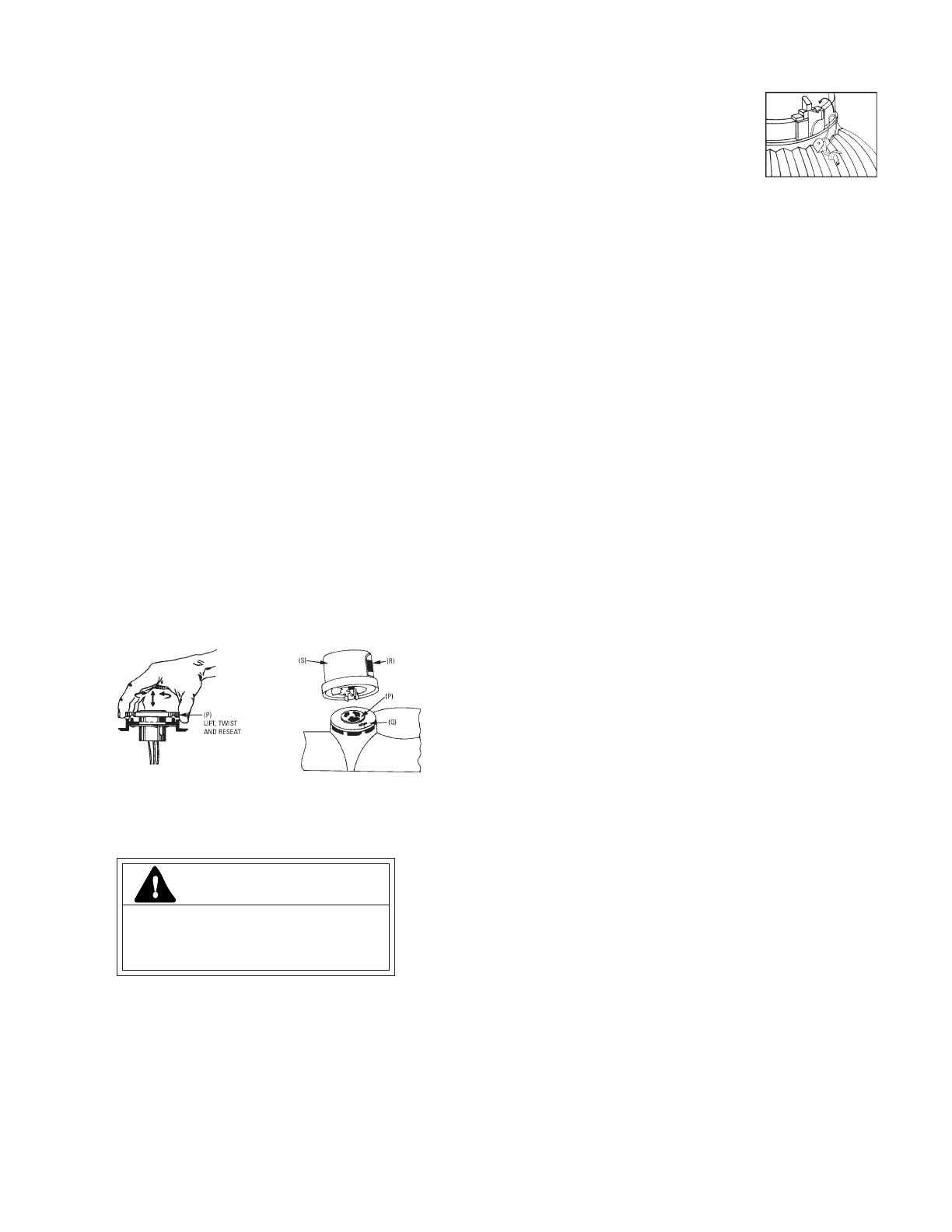
To orient the photoelectric receptacle
(See illustration B)
Grasp spring loaded PE control receptacle (P) and lift up,
rotate receptacle clockwise until “North’’ arrow (Q) printed on
top of receptacle points North. Reseat receptacle. If this
orientation prevents light from reaching control window (R),
rotate arrow to point South.
To install the photoelectric control
(See illustration C)
Insert the PE control (S) in its’ proper keyed socket slots
on top of fixture, making certain that the largest of the three
prongs is inserted onto the slot located adjacent to the word
“North’’ on the socket. Press downward and twist clockwise
about 1/8 of a turn to secure.
For UL fixtures, attach optical assembly to hood by aligning
mounting holes in top of reflector with two holes in fixture
housing and attach with screws and
washers, making sure dimple in top of
reflector is oriented to mounting end of
unit.
STEP 6
Wiring luminaire to electrical circuit
Different catalog numbers are
furnished for use on120-volt or 240-volt service. Ballasts are
not reconnectable and are intended for use only as specified
on label. Verify that supply voltage is correct by comparing it
to nameplate.
120-volt luminaires are furnished with one black and one
white wiring lead. White lead is neutral and should be
connected to white neutral service lead. Black line lead
should be connected to black line service lead.
For UL fixtures, all wiring connections should be made in
accordance with National Electric Code and any applicable
local code requirements. Ensure that all connections are
properly insulated and that luminaire is grounded correctly.
All wiring connections should be made and then concealed
in mounting arm. Install plug in open end of arm and secure
with (2) screws provided. The remaining wire should now be
inserted into conduit (not provided) and the conduit
secured to connector which is installed in connector cap. The
opposite end of conduit should be terminated by second
conduit connector which is then joined to junction box as
shown.
For all fixtures, 240-volt luminaires are normally intended
for use on three-wire electrical service, 240-volts to ballast and
120-volts to PE control. 240-volt units are furnished with
three wiring leads, two black and one white. Two black leads
should be connected to two incoming black line service leads
and white to incoming white neutral. Some 240-volt service
are two-wire and will be furnished with two black leads for
operation of both ballast and PE control at 240-volts. These
two black leads should be connected to two black service
leads as outlined above.
Units with terminal board have terminals plainly marked
“L’’ for line and “N’’ for neutral, or “L’’ and “L’’ for both
sides of line in two-wire system unit and “L’’, “L” for line and
“N’’ for neutral in a three-wire system unit. Always check
terminal screws after final tightening to make sure that they
are tight.
STEP 7
Checking out the system
Your luminaire should be ready for operation. Make sure
lamp and photoelectric control are correctly installed. Check
PE control to insure it faces North. Turn on power. Cover PE
control window with black tape, a glove or some masking
object.
A high pressure sodium lamp should light within one to
two minutes. It will take three to four minutes for lamp to
warm-up to full brightness. A mercury vapor lamp will also
light within one to two minutes but will take five to seven
minutes to reach full brightness.
Remove black tape, etc., and luminaire should shut-off
automatically.
ILLUSTRATION CILLUSTRATION B
STEP 4
Installation of lamp into socket
ILLUSTRATION D
CAUTION
Risk of burn
• Allow lamp/fixture to cool before
handling
Use only lamps specified on nameplate. The lamp should
now be screwed into socket, making sure lamp is firmly seated
to insure good electrical contact.
STEP 5
Installation of optical assembly to hood
Optical assembly should be handled carefully to prevent
damage from surface abrasion or severe impact. For Non UL
fixtures, attach optical assembly to hood by snapping two
latches on reflector to “ears’’ on hood.
(See illustration D.)

