M-02-22
REV. (-01)
MARCH 2003


LIFT CORP.
11921 Slauson Ave.
Santa Fe Springs, CA. 90670
CUSTOMER SERVICE:
TELEPHONE (562) 464-0099 TOLL FREE (800) 227-4116
FAX: (888) 771-7713
WARRANTY/ RMA POLICY & PROCEDURE
NOTE: For latest version Manuals (and replacements), download
Manuals from Maxon’s website at www.maxonlift.com.
LIFTGATE WARRANTY
Term of Warranty: 2 Years from Date of In-Service (In service date cannot exceed 3 months from ship date.)
Type of Warranty: Full Parts and Labor
This warranty shall not apply unless the product is installed, operated and maintained in accordance with MAXON Lift’s specifications as set forth
in MAXON Lift’s Installation, Operation and Maintenance manuals. This warranty does not cover normal wear, maintenance or adjustments,
damage or malfunction caused by improper handling, installation, abuse, misuse, negligence, or carelessness of operation. In addition, this
warranty does not cover equipment that has had unauthorized modifications or alterations made to the product.
MAXON agrees to replace any components which are found to be defective during the first 2 years of service, and will reimburse for labor based
on MAXON’s Liftgate Warranty Flat Rate Schedule. (Copy of the Flat Rate is available at www.maxonlift.com.)
All warranty repairs must be performed by an authorized MAXON warranty facility. For any repairs that may exceed $500, including parts and
labor, MAXON’s Technical Service Department must be notified and an “Authorization Number” obtained.
All claims for warranty must be received within 30 Days of the repair date, and include the following information:
1. Liftgate Model Number and Serial Number
2. The End User must be referenced on the claim
3. Detailed Description of Problem
4. Corrective Action Taken, and Date of Repair
5. Parts used for Repair, Including MAXON Part Number(s)
6. MAXON R.M.A. # and/or Authorization # if applicable (see below)
7. Person contacted at MAXON if applicable
8. Claim must show detailed information I.e. Labor rate and hours of work performed
Warranty claims can also be placed on-line at www.maxonlift.com. On-line claims will be given priority processing.
All claims for warranty will be denied if paperwork has not been received or claim submitted via Maxon website for processing by MAXON’s
Warranty Department within 30 days of repair date.
All components may be subject to return for inspection, prior to the claim being processed. MAXON products may not be returned without prior
written approval from MAXON’s Technical Service Department. Returns must be accompanied by a copy of the original invoice or reference with
original invoice number and are subject to a credit deduction to cover handling charges and any necessary reconditioning costs. Unauthorized
returns will be refused and will become the responsibility of the returnee.
Any goods being returned to MAXON Lift must be pre-approved for return, and have the R.M.A. number written on the outside of the package in
plain view, and returned freight prepaid. All returns are subject to a 15% handling charge if not accompanied by a detailed packing list. Returned
parts are subject to no credit and returned back to the customer.
Defective Parts requested for return must be returned within 30 days of the claim date for consideration to:
MAXON Lift Corp.
16205 Distribution Way, Cerritos, CA 90703
Attn: RMA#__
MAXON’s warranty policy does not include the reimbursement for travel time, towing, vehicle rental, service calls, oil, batteries or loss of income
due to downtime. Fabrication or use of non Maxon parts, which are available from MAXON, are also not covered.
MAXON’s Flat Rate Labor Schedule takes into consideration the time required for diagnosis of a problem.
All Liftgates returned are subject to inspection and a 15% restocking fee. Any returned Liftgates or components that have been installed or not
returned in new condition will be subject to an additional reworking charge which will be based upon the labor and material cost required to return
the Liftgate or component to new condition.
PURCHASE PART WARRANTY
Term of Warranty: 1 Year from Date of Purchase.
Type of Warranty: Part replacement only
MAXON will guarantee all returned genuine MAXON replacement parts upon receipt and inspection of parts and original invoice.
All warranty replacements parts will be sent out via ground freight. If a Rush Shipment is requested all
freight charges will be billed to the requesting party.

TABLE OF CONTENTS
WARNINGS......................................................................................................6
LIFTGATE TERMINOLOGY ................................................................................................... 7
PERIODIC MAINTENANCE CHECKLIST ............................................................................. 8
CHANGING HYDRAULIC FLUID ........................................................................................... 9
PLATFORM ADJUSTMENT ................................................................................................ 10
REPLACING PLATFORM TORSION SPRING .................................................................... 12
SAFETY HOOK MAINTENANCE ........................................................................................ 14
PARTS BREAKDOWN..................................................................................15
72-150SA/TE-20SA FINAL ASSEMBLY.............................................................................. 16
EXTENSION PLATE ASSEMBLY ....................................................................................... 17
LIFT FRAME & PARALLEL ARMS...................................................................................... 18
PLATFORM & FLIPOVER ASSEMBLY............................................................................... 20
PUMP COVER ................................................................................................................... 21
GRAVITY DOWN HYDRAULIC COMPONENTS.................................................................. 22
12 VDC POWER UNIT (GRAVITY DOWN).......................................................................... 23
POWER DOWN HYDRAULIC COMPONENTS................................................................... 24
12 VDC POWER UNIT (POWER DOWN) ........................................................................... 25
DECALS ............................................................................................................................ 26
CONTROL SWITCH AND POWER CABLE ........................................................................ 27
SCHEMATICS...............................................................................................28
HYDRAULIC SCHEMATIC (GRAVITY DOWN) .................................................................... 29
ELECTRICAL SCHEMATIC - GRAVITY DOWN .................................................................. 30

HYDRAULIC SCHEMATIC - POWER DOWN ..................................................................... 31
ELECTRICAL SCHEMATIC - POWER DOWN................................................................... 32
TROUBLESHOOTING..................................................................................33
PLATFORM WILL NOT RAISE ............................................................................................ 34
PLATFORM RAISES BUT LEAKS DOWN.......................................................................... 35
PLATFORM RAISES PARTIALLY AND STOPS .................................................................. 36
LIFTGATE WILL NOT LIFT RATED CAPACITY ................................................................... 37
PLATFORM RAISES SLOWLY ........................................................................................... 38
PLATFORM WILL NOT LOWER, LOWERS TOO SLOWLY, OR LOWERS TOO QUICKLY .. 39
TABLE OF CONTENTS - Continued

11921 Slauson Ave. Santa Fe Springs, CA. 90670 (800) 227-4116 FAX (888) 771-7713
6
• Keep decals clean and legible. If decals are defaced or missing, replace them. Free replacement
decals are available from Maxon Parts Department.
• Consider the safety and location of bystanders and location of nearby objects when operating the
Liftgate. Stand to one side of the platform while operating the Liftgate
• Do not stand under, or allow obstructions under the platform when lowering the Liftgate. Be sure
your feet are clear of the Liftgate.
• Keep fingers, hands, arms, legs, and feet clear of moving Liftgate parts (and platform
edges) when operating the Liftgate.
• Wear apppropriate safety equipment such as protective eyeglasses, faceshield and clothing while
performing maintenance on the Liftgate and handling the battery. Debris from drilling and contact
with battery acid may injure unprotected eyes and skin.
• Disconnect Liftgate power cable from battery before repairing or servicing Liftgate.
• Do not allow untrained persons to operate the Liftgate.
• Be careful working by an automotive type battery. Make sure the work area is well ventilated and
there are no flames or sparks near the battery. Never lay objects on the battery that can short the
terminals together. If battery acid gets in your eyes, immediately seek first aid. If acid gets on your
skin, immediately wash it off with soap and water.
• If an emergency situation arises (vehicle or Liftgate) while operating the Liftgate, release the control
Toggle Switch and the Liftgate will stop.
Comply with the following WARNINGS while maintaining Liftgates. See Operation Manual
M-02-21 for operating safety requirements.
• Read and understand the instructions in this Maintenance Manual before performing mainte-
nance on the Liftgate.
• Before operating the Liftgate, read and understand the operating instructions in Operation Manual
M-02-21.
• Comply with all WARNING and instruction decals attached to the Liftgate.
• A correctly installed Liftgate operates smoothly and reasonably quiet. The only noticeable noise
during operation comes from the pump unit while the platform is raised. Listen for scraping, grating
and binding noises and correct the problem before continuing to operate Liftgate.
• If it is necessary to stand on the platform while maintaining the Liftgate, keep your feet and any
objects clear of the inboard edge of the platform. Your feet or objects on the platform could be
trapped between the platform and the Liftgate extension plate.
• Never perform unauthorized modifications on the Liftgate. Modifications may result in early failure of
the Liftgate and may create hazards for Liftgate operators and maintainers.
• Use only Maxon Authorized Parts for replacement parts. Provide Liftgate model and serial num-
ber information with your parts order. Order replacement parts from:
WARNINGS
!!
!!
!
• Correctly stow platform when not in use. Extended platforms could create a hazard for
people and vehicles passing by.
MAXON LIFT CORP. Customer Service
11921 Slauson Ave., Santa Fe Springs, CA 90670
Phone: (800) 227-4116
• To order parts by e-mail, submit orders to part[email protected].

11921 Slauson Ave. Santa Fe Springs, CA. 90670 (800) 227-4116 FAX (888) 771-7713
7
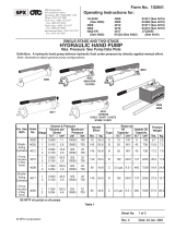
LIFTGATE TERMINOLOGY
72-150SA & TE-20SA
CONTROL
SWITCH
LIFT
CYLINDER
PARALLEL
ARM
PLATFORM
MAIN FRAME
FLIPOVER
LIFT FRAME
PUMP
ASSEMBLY
EXTENSION
PLATE
OPENER

11921 Slauson Ave. Santa Fe Springs, CA. 90670 (800) 227-4116 FAX (888) 771-7713
8
PERIODIC MAINTENANCE CHECKLIST
Visually check the entire Liftgate for excessively worn parts and broken welds, especially the
Hinge Pins. See PARTS BREAKDOWN section for replacement parts. Also, do the Semi-
annual and Quarterly Maintenance checks.
Annually
Quarterly
Semi-annually
Visually check the Platform Hinge Pins for excessive wear and broken welds. See PARTS
BREAKDOWN section for replacement parts. Also, do the Quarterly Maintenance checks.
Never operate the Liftgate with parts loose or missing.
WARNING
!!
!!
!
+40 to +150 Degrees F - Grade ISO 32
Below + 40 Degrees F - Grade ISO 15
Check the Hydraulic Fluid level in the Pump Reservoir. If hydraulic fluid must be added, select
the correct grade of fluid to use at your location. Recommended hydraulic fluids are listed in
TABLE 1 and TABLE 2
If Hydraulic Fluid appears contaminated, refer to the CHANGING HYDRAULIC FLUID
procedure on following page.
Keep track of the grade of Hydraulic Fluid in the Pump Reservoir and never mix two different
grades of fluid.
Check all Hoses and Fittings for chaffing and fluid leaks. Replace if necessary.
Check electrical wiring for chaffing and make sure wiring connections are tight and free of
corrosion.
Check that all WARNING and instruction decals are in place and legible.
Check that all roll pins are in place and protrude evenly from both sides of Hinge Pin collar.
Replace roll pins if necessary.
DIULFCILUARDYH23OSI
SDNARBDEDNEMMOCERREBMUNTRAP
DAEMESOR051VMMILUARDYH
NORVEHC23VMWALIOCILUARDYH
LLEHS23TSULLET
NOXXE23NSIVINU
LIBOM31LIOCILUARDYH
DIULFCILUARDYH51OSI
SDNARBDEDNEMMOCERREBMUNTRAP
NOXXE31JSIVINU
NOXXEA6065-L-LIM
NORVEHC
NOITAIVA
ADIULFCILUARDYH
LLEHS4DIULFLLEHSOREA
LIBOMAFHOREA
TABLE 1
TABLE 2

11921 Slauson Ave. Santa Fe Springs, CA. 90670 (800) 227-4116 FAX (888) 771-7713
9
1. Remove the Pump Cover. Place empty 5 Gallon
Bucket under Drain Plug (FIG. 1).
GRAVITY DOWN LIFTGATES
2. Lower Platform to ground. Pull out (no threads)
Drain Plug (FIG. 1). Drain hydraulic fluid from
system. Re-install Drain Plug.
3. Pull out (no threads) Filler Cap (FIG. 1) and refill
reservoir with Hydraulic Fluid to 4” level shown in
FIG. 1. Use correct grade of hydraulic fluid for your
location. See TABLE 1 and TABLE 2 for
recommended fluids.
4. Reinstall Filler Cap (FIG. 1).
3. Disconnect the Motor Power Cable (FIG. 2) from
bottom Starter Solenoid. Lower the Platform while
draining the remaining hydraulic fluid from
system. Reinstall Drain Plug. Reconnect the
Motor Power Cable to bottom Starter Solenoid.
6. Reinstall Filler Cap (FIG. 1).
+40 to +150 Degrees F - Grade ISO 32
Below + 40 Degrees F - Grade ISO 15
LIFTGATE SHOWN WITH
GRAVITY DOWN PUMP & MOTOR
FIG. 1
POWER DOWN PUMP
FIG. 2
BOTTOM
STARTER
SOLENOID
MOTOR POWER
CABLE
CHANGING HYDRAULIC FLUID
2. Open and raise Platform to vehicle bed height. Pull
out (no threads) Drain Plug (FIG. 1). Drain hydraulic
fluid.
CAUTION
Keep dirt, water and other contaminants from entering the hydraulic system.
Before opening the hydraulic fluid reservoir filler cap, drain plug and hydraulic
lines, clean up contaminants that can get in the openings. Also, protect the open-
ings from accidental contamination.
5. Raise Platform to vehicle bed height. Check hydraulic
fluid again and, if needed, add more hydraulic fluid
until Sight Glass (FIG. 1) is half full.
+40 to +150 Degrees F - Grade ISO 32
Below +40 Degrees F - Grade ISO 15
POWER DOWN LIFTGATES
DRAIN
PLUG
FILLER
CAP
4” MIN
RESERVOIR
1. Remove the Pump Cover. Place empty 5 Gallon
Bucket under Drain Plug (FIG. 1).
4. Pull out (no threads) Filler Cap (FIG. 1) and refill
reservoir with Hydraulic Fluid to 4” level shown in
FIG. 1. Use correct grade of hydraulic fluid for your
location. See TABLE 1 and TABLE 2 for
recommended fluids.

11921 Slauson Ave. Santa Fe Springs, CA. 90670 (800) 227-4116 FAX (888) 771-7713
10
PLATFORM ADJUSTMENT
NOTE: Before doing the following procedure,
make sure vehicle is parked on level ground.
PLATFORM EDGE ABOVE BED LEVEL
FIG. 3
LEVEL LINE
SHACKLES DO NOT TOUCH GROUND
FIG. 5
PLATFORM & SHACKLES
TOUCH GROUND
FIG. 4
1. Make sure Platform is at ground level. Unfold
the Platform and Flipover. The Shackles and
the outboard edge of Platform must touch the
ground at the same time as shown in FIG. 4.
If the Shackles and the outboard edge of Plat-
form are touching the ground, RAISE Platform
to bed height. Outboard edge of Platform
should be above bed level (FIG. 3). If indications
are correct (FIGS. 3 & 4), Liftgate is installed
correctly and no adjustment is needed. If indica-
tions are incorrect, continue with instruction 2.
2. Make sure Platform is still at ground level. If
the Shackle is not touching the ground, measure
and compare distance “A” (FIG. 5) with
TABLE 3 to determine the correct shim. Make
shims as needed (FIG. 6). Weld shim as shown
in FIG. 7.
“A”
(TABLE 3)
WELDING SHIMS (CURBSIDE SHOWN)
FIG. 7
2 PLACES
“W”
(TABLE 3)
SHIM (1/16”, 1/8”, 3/16”, or 1/4”)
MADE FROM STEEL FLAT
FIG. 6
2-1/4”
NOTE: If the Platform is like FIG. 5, do instruc-
tion 2. If the Platform touches and the Shackle
does not (FIG. 8), skip 2 and do 3.
1-1/2”
TABLE 3
MROFTALPESIAR
)DRAOBTUO(EGDE
)"A"(ECNATSIDSIHT
MIHSDERIUQER
SSENKCIHT
EZISDLEW
"W"
"61/11"61/1"61/1
"8/3-1"8/1"8/1
"61/1-2"61/3"61/3
"4/3-2"4/1"4/1
SHIM
(TABLE 3)
PLATFORM
SHACKLE
(REF)
CENTERED
(TOP EDGES FLUSH)

11921 Slauson Ave. Santa Fe Springs, CA. 90670 (800) 227-4116 FAX (888) 771-7713
11
GRINDING PLATFORM STOPS
(CURBSIDE SHOWN)
FIG. 9
PLATFORM
SHACKLE
(REF)
PLATFORM
STOP
MROFTALPREWOL
)DRAOBTUO(EGDE
)"B"(ECNATSIDSIHT
MORFLATEMDNIRG
POTSMROFTALP
"61/11"61/1
"8/3-1"8/1
"61/1-2"61/3
"4/3-2"4/1
TABLE 4
PLATFORM DOES NOT
TOUCH GROUND
FIG. 8
“B”
(TABLE 4)
3. Make sure Platform is still at ground level. If
the Platform is not touching the ground,
measure and compare distance“B” (FIG. 8)
with TABLE 4 to determine how much to grind
from the Platform Stops (FIG. 9). Grind
correct amount of metal (TABLE 4)
from Platform Stop as shown in FIG. 9.
GRIND HERE
(TABLE 4)
4. RAISE the Platform, then LOWER it to the
ground. Platform and Shackle should touch the
ground at the same time as shown in FIG. 4.
PLATFORM ADJUSTMENT - Continued

11921 Slauson Ave. Santa Fe Springs, CA. 90670 (800) 227-4116 FAX (888) 771-7713
12
REPLACING PLATFORM TORSION SPRING
1. Manually fold Flipover onto Platform .
3. Drive out the roll pin from pin collar on the
Platform Hinge Bracket. Drive the platform
Hinge Pin outboard from the Shackle just
enough to free the torsion spring (FIG. 10).
Remove spring from Shackle.
4. Install the Torsion Spring as
shown in (FIG. 11). Make sure
the long leg of the spring is
inserted in the bracket located
on the Shackle. Make sure the
short end of the spring is
visible and resting against the
block on the Platform Hinge
Bracket (FIG. 11).
2. Raise Liftgate to a convenient work height
to gain access and release tension on the
Torsion Spring.
To prevent injury and equipment damage,
make sure there is no tension on torsion
spring before removing hinge pin.
CAUTION
!!
!!
!
ROLL PIN
(REMOVED)
SHACKLE
FIG. 10
PLATFORM
HINGE PIN
TORSION
SPRING
PIN
COLLAR
BLOCK
LONG LEG
FIG. 11
PLATFORM
HINGE
BRACKET
BRACKET
SHACKLE
SHORT LEG

11921 Slauson Ave. Santa Fe Springs, CA. 90670 (800) 227-4116 FAX (888) 771-7713
13
5. Drive Platform Hinge Pin inboard to correct position through the Platform Hinge Bracket
(FIG. 12). Line up the hole in the Platform Hinge Pin with the hole in the Pin Collar. Install
the roll pin through the Pin Collar until roll pin protrudes equally from both sides of the collar
(FIG. 12).
ROLL PIN
(INSTALLED)
6. Operate the Liftgate according to instructions in Operation Manual M-02-21 to make sure
it operates correctly.
FIG. 12
PLATFORM HINGE
BRACKET
PIN
COLLAR
PLATFORM
HINGE PIN
REPLACING PLATFORM TORSION SPRING
-Continued

11921 Slauson Ave. Santa Fe Springs, CA. 90670 (800) 227-4116 FAX (888) 771-7713
14
SAFETY HOOK MAINTENANCE
GREASE ALL HOLES THE
ROD PASSES THRU
GREASE FRONT SURFACE OF
HOOK WITH AUTOMOTIVE
GREASE
EXTENSION
PLATE
SAFETY
HOOK
PLATFORM
PLATFORM LOOP
(WRONG POSITION)
BEND IN
THIS
DIRECTION
FIG. 13
CHECK SAFETY HOOK FUNCTION
LOOP ADJUSTMENT
FIG. 14
1. When raising Platform to stowed position,
listen for sound of Platform Loop striking
Safety Hook.
2. When the Liftgate is stowed, see if Platform
Loop is positioned above the Safety Hook
as shown in FIG. 13.
1. If the Safety Hook is not positioned correctly,
LOWER Platform to ground level (Operation
Manual M-02-21).
2. Adjust by bending the Platform Loop as shown
in FIG. 14.
3. Stow the Platform and check for correct Safety
Hook position. Repeat adjustment if required.
CORRECT
POSITION

11921 Slauson Ave. Santa Fe Springs, CA. 90670 (800) 227-4116 FAX (888) 771-7713
15
PARTS BREAKDOWN

11921 Slauson Ave. Santa Fe Springs, CA. 90670 (800) 227-4116 FAX (888) 771-7713
16
72-150SA/TE-20SA FINAL ASSEMBLY
REFER TO PLATFORM &
FLIPOVER ASSEMBLY
REFER TO LIFT FRAME
& PARALLEL ARMS
REFER TO PUMP COVER,
HYDRUALIC COMPONENTS, &
POWER UNITS
REFER TO EXTENSION
PLATE ASSEMBLY
2
3
3
3
4
1
2
7
5
6
METI.YTQ.ONTRAPNOITPIRCSED
1
150-504302.GL"4/1-3,NIP
2
5614122NIPLLOR
3
4686252.GL"4,NIP
4
1756352EBULFLES,GNIRAEB
5
240-410009.GL"1x61-"8/3,TLOBDHXEH
6
240-110209"8/3,REHSAWKCOL
7
120-004309"8/3,HTOOTLANRETXE,REHSAWKCOL

11921 Slauson Ave. Santa Fe Springs, CA. 90670 (800) 227-4116 FAX (888) 771-7713
17
EXTENSION PLATE ASSEMBLY
1
VIEWED FROM UNDER
EXTENSION PLATE
2
3
5
3B
3A
3D
4
3C
METI.YTQ.ONTRAPNOITPIRCSED
1
6446702TEVIR
2
1571050ETALPNOXAM
3
1000362ETALPNOISNETXE
A3
1606102ELDNAH
B3
2165102KCOLBPOTS
C3
1243512GNIRPS,REVEL
D3
1143512KOOHYTEFAS
4
1543512GNIRPSNOISNETXE
5
1110550)PIRG(ELDNAHREBBUR

11921 Slauson Ave. Santa Fe Springs, CA. 90670 (800) 227-4116 FAX (888) 771-7713
18
LIFT FRAME & PARALLEL ARMS
8B
8B
8A
8A
1
9
13
14A
11
14
12
2
1
7
4
3
2
5
8
8B
16
16A
11
10
15
6
15C
15D
15B
15A

11921 Slauson Ave. Santa Fe Springs, CA. 90670 (800) 227-4116 FAX (888) 771-7713
19
METI.YTQ.ONTRAPNOITPIRCSED
1
5614122NIPLLOR
2
2686252.GL"4,NIP
3
110-250082)HR(TNEMDLEWELKCAHS
4
120-250082)HL(TNEMDLEWELKCAHS
5
1038062.GL"4/1-7,NIP
6
1189262.GL"41,NIP
7
110-948082GNIRPSNOISROT
8
1050082EMARFTFIL
A8
250-738162CITSALP-DEGNALF,GNIHSUB
B8
430-619062EBULFLES,GNIRAEB
9
1390082REDNILYC,NIP
01
120-780082TNEMDLEWNIP
11
24-330509NIPLLOR
21
110-780082TNEMDLEWNIP
31
1580082RELLOR
41
1840082HRMRALELLARAP
A41
230-619062EBULFLES,GNIRAEB
51
1870082RENEPO
A51
110-280082RELLOR
B51
101-530009.GL"2/1-3X31-"2/1,WERCSPAC
C51
141-000209"2/1,REHSAWTALF
D51
101010931-"2/1,TUNKCOL
61
1770082HLMRALELLARAP
A61
230-619062EBULFLES,GNIRAEB
LIFT FRAME & PARALLEL ARMS

11921 Slauson Ave. Santa Fe Springs, CA. 90670 (800) 227-4116 FAX (888) 771-7713
20
1
PLATFORM & FLIPOVER ASSEMBLY
METI.YTQ.ONTRAPNOITPIRCSED
1
110-830082)EDIW"27(REVOPILF
120-830082)EDIW"48(REVOPILF
2
22-330009.GL"4/1-1x02-"2/1,WERCSPAC
3
21-61010902-"2/1,DAEHNIHT,TUNKCOL
4
110-340082)EDIW"27(MROFTALP
120-340082)EDIW"48(MROFTALP
A4
230-619062EBULFLES,GNIRAEB
2
2
3
3
4A
4
Page is loading ...
Page is loading ...
Page is loading ...
Page is loading ...
Page is loading ...
Page is loading ...
Page is loading ...
Page is loading ...
Page is loading ...
Page is loading ...
Page is loading ...
Page is loading ...
Page is loading ...
Page is loading ...
Page is loading ...
Page is loading ...
Page is loading ...
Page is loading ...
Page is loading ...
/