GROUNDING INSTRUCTIONS
:
Connect the supply ground wire, fixture ground wire, and mounting bar
ground wire (pre attached) using the supplied wiring connector. Gently try
to remove the wires from the connector. If you can remove the wires,
carefully re-do the wiring connection.
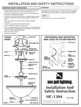
INSTALLATION HC-1565
Secure mounting bar (A) to outlet box with outlet box screws (not
supplied). Thread nut (B) on nipple (C) so that 5 threads are exposed
above nut (B). Thread nipple (C) into mounting bar (A) and secure
with nut (B). Thread screw collar (E) to nipple (C).
IMPORTANT: DO NOT ATTACH FIXTURE DIRECTLY TO OUTLET BOX.
STEP 1:
FOR CHAIN HUNG
Using 2 pairs of pliers or chain breaks, open one link of chain (S) and
connect it to the fixture loop (I) at the top of the fixture. Please be
sure to open chain link in an outward motion.
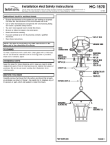
STEP 2:
Slide the screw collar ring (G) and canopy (H), in that order, over
chain (S). Open one link on the other end of the chain (S) and attach
it to the screw collar (E) which has been mounted to the ceiling
nipple (C). BE SURE TO CLOSE ALL CHAIN LINKS COMPLETELY.
STEP 3:
Thread mounting screws (K) into offset mounting bar (N). Run
mounting screws (K) all the way down to their heads. Secure offset
mounting bar (N) to the outlet box (raised side to top as illustrated)
using outlet box screws (not supplied).
STEP 1:
FOR FLUSH MOUNT
Remove fixture loop (I) from fixture. Feed fixture wires through center
of flush canopy. Secure flush canopy to fixture by installing lock
washer and nut over center nipple.
STEP 2:
WIRING
STEP 1:
A. Use a listed wire connector to connect the fixture hot wire (black
wire, or round and smooth tracer) to the supply hot wire.
B. Use a listed wire connector to connect the fixture common wir
e
(white wire, or square and rigid) to the supply common wire.
C. Gently try to remove the wires from the connector. If you can
remove the wires, carefully re-do the wiring connection.
STEP 2:
Make sure no bare wires can be seen outside wire connectors. After
wires are connected, tuck them carefully inside outlet box. Push the
fixture firmly over the mounting screws (F) and against the wall.
Secure canopy (I) in place with cap nuts (E).
Make sure no bare wires can be seen outside wire connectors.
Install lamps.
Place flush canopy to ceiling so mounting scr
ews (K) protrude
through flush canopy and secure by threading cap nuts to mounting
screws (K).
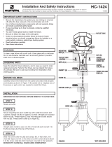
FINAL ASSEMBLY
STEP 1: CHAIN HUNG ONLY
STEP 2: FLUSH MOUNT ONLY
STEP 3:
Raise diffuser (O) over bottom nipple (P) and secure by placing
decorative cup (M) to diffuser (O), and threading finial (L) to bottom
nipple (P). Arms (J) should protrude through diffuser (O). Thread ball
nuts (F) onto arms to secure.
STEP 4: