Legrand RS-250-LA Installation guide

Type
Installation guide
Wattstopper
®
PIR Wall Switch Convertible Occupancy Sensor
Détecteur de présence IRP à interrupteur mural convertible
Sensor de Desocupación de pared configurable
Installation Instructions • Instructions d’Installation • Instrucciones de Instalación
No: 24219 – 08/16 rev. 1
Catalog Number • Numéro de Catalogue • Número de Catálogo: RS-250
Country of Origin: Made in China • Pays d’origine: Fabriqué en Chine • País de origen: Hecho en China
SPECIFICATIONS
Voltage .............................................................. 120VAC, 60Hz
Load (Single Pole Circuit)
Incandescent or fluorescent .......................... 0-600 Watts
Fan motor ............................................................... 1/6 hp
Time Delay Adjustment ....................15 seconds to 30 minutes
Light Level Adjustment ....................................... 10 fc to 150 fc
Environment ..................................................... Indoor use only
Operating Temperature .............32° to 131°F (0° to 55°C)
Humidity ...................................95% RH, non-condensing
Tools Needed
Insulated Screwdriver
Wire Strippers
DESCRIPTION AND OPERATION
The RS-250 PIR Wall Switch Convertible Occupancy Sensor is designed to replace a standard light or fan switch. It is ideal for any
indoor area in a space where occupancy sensor-based Manual ON/OFF controls are desirable.
Like a standard switch, you press the ON/OFF button to turn the light or fan (controlled load) ON and OFF. Unlike a standard switch, the
RS-250 automatically turns OFF the controlled load after the coverage area has been vacant for a period of time (Time Delay). If motion
is detected within 30 seconds after it automatically turns OFF, the RS-250 automatically turns the load back ON.
While the sensor is factory preset as a Vacancy Sensor with manual ON operation, it can be adjusted to work as an Occupancy Sensor
that turns the controlled load ON automatically upon detection of occupancy in the area.
Lighted Switch
To help you locate the RS-250 in a dark room, the amber LED illuminates the ON/OFF button while the controlled load is OFF. When
the controlled load is ON, the LED is OFF.
Operating Modes
There are two operating modes to select from during set up:
MODE 1: Vacancy sensor (Manual-ON/OFF, Auto-OFF): The user must press the ON/OFF button to turn
the load ON. The RS-250 keeps the load ON until no motion is detected for the selected time delay period
(adjustable from 15 seconds to 30 minutes). There is a 30 second reset delay. If motion is detected during
this time, the sensor turns the load back ON automatically. After the reset delay time has elapsed, the ON/
OFF button must be pressed to turn ON the load.
MODE 2: Occupancy sensor (Auto-ON/OFF with manual control and reset to auto after 5 minutes of
vacancy): The load turns ON and OFF automatically based on occupancy detection. The RS-250 keeps the
load ON until no motion is detected for the selected time delay period. If the load is turned OFF manually,
automatic-ON is re-enabled when no motion is detected for 5 minutes. This prevents the load from being
turned ON after it was deliberately turned OFF.
Time Delay
The time delay can be selected by the user during set up. It can be adjusted from 15 seconds up to 30 minutes. For additional
information on how to adjust it, please read the SENSOR ADJUSTMENT & PROGRAMMING section of this installation manual.
Light Level
When the sensor is set for occupancy sensor Mode 2 (Auto-ON/OFF) the light level feature prevents the sensor from automatically
turning the lights ON if there is already enough light in the area. To adjust the light level, please read the SENSOR ADJUSTMENT &
PROGRAMMING section of this installation manual.
Coverage Area
The RS-250 has a maximum range of 180 degrees and a coverage area of 600 sq. feet (56 sq. meters). The sensor must have a clear
and unobstructed view of the coverage area. Objects blocking the sensors lens may prevent detection thereby causing the light to turn
OFF even though someone is in the area.
NOTE: Windows, glass doors, and other transparent barriers will obstruct the sensors view and prevent detection.

P

P
Fig. 1: Sensor Coverage Area
2
INSTALLATION AND WIRING
1. Prepare the switch box.
After the power is turned OFF at the circuit breaker box, remove the existing wall plate and
mounting screws. Pull the old switch out from the wall box.
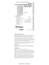
2. Identify the type of circuit.
In a Single Pole Circuit (see Fig. 2), two single wires connect to two screws on the existing switch.
A ground wire may also be present and connected to a ground terminal on the old switch. A neutral
wire should also be present in the wall box.
CAUTION - FOR YOUR SAFETY: Connecting a proper ground to the sensor provides protection against
electrical shock in the event of certain fault conditions. If a proper ground is not available, consult with a qualied electrician before
continuing installation.
Only connect the RS-250 to a Single Pole Circuit. The RS-250 is not suitable for 3-way switching. If the existing wiring does not
match the description for a Single Pole Circuit, you should consult with a qualified electrician.
3. Prepare the Wires.
Tag the wires connected to the existing switch, so that they can be identified later. Disconnect the wires.
Make sure the insulation is stripped off the wires to expose their copper cores to the length indicated by the
“Strip Gage,” (in Fig. 3) (approx. 1/2 inch).
4. Wire the sensor.
Twist the existing wires together with the wire leads on the RS-250 sensor as indicated below. Cap them securely using the wire
nuts provided (See Fig 4).
Connect the green or non-insulated (copper) GROUND wire from the circuit to the
green terminal on the RS-250.
Connect the NEUTRAL wire from the circuit and from the lamp (LOAD) to the white
wire on the RS-250.
Connect the power wire from the circuit box (HOT) to the black wire on the RS-250.
Connect the power wire to the lamp (LOAD) to the red wire on the RS-250.
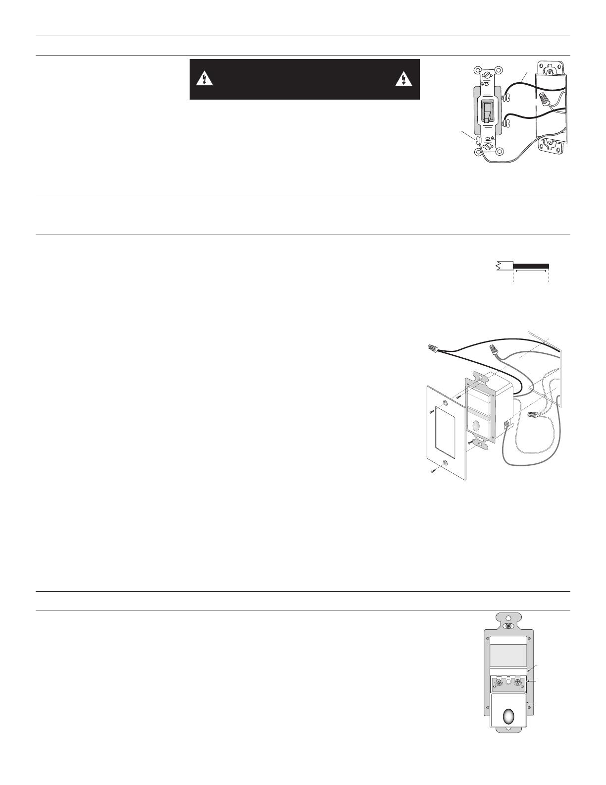
5. Put the RS-250 in the wall box.
Position the lens above the ON/OFF button (lens at top, button at bottom) and secure it to
the wall box with the screws provided.
6. Restore power to the circuit.
Turn ON the breaker or replace the fuse.
7. Test the sensors operation.
See TEST MODE.
8. Review SENSOR ADJUSTMENT & PROGRAMMING below.
If you want to make adjustments, follow the instructions in SENSOR ADJUSTMENT &
PROGRAMMING.
9. Install cover plate.
Install industry standard decorator wall switch cover plate (not included).
Initial Power-up Delay: There is an initial warm-up period the first time power is applied to the unit, and after a power failure lasting
more than 5 minutes. If the sensor is in Mode 2, (Automatic-ON) it may take up to 1 minute before the lights turn ON. However, the
lights can be turned ON/OFF manually by pressing the ON/OFF button at any time when power is supplied to the unit.
SENSOR ADJUSTMENT AND PROGRAMMING
To program the RS-250, you use controls located under the ON/OFF button. The wall switch cover plate must be
removed to gain access to the mode button and adjustment trimpots under the ON/OFF button.
1. Firmly grasp the side edges of the Lock Bar and gently pull it away from the switch face until it clicks. Do
NOT attempt to pull the Lock Bar off of the switch!
2. Firmly grasp the side edges of the ON/OFF button. Slide the button downward approximately 1/2 inch to
expose the mode button and adjustment trimpots.
Setting up the Operating Mode
Select the operating mode by pressing the Mode button. The amber LED behind the switch button blinks to
indicate the selected mode:
One blink indicates Mode 1 (Vacancy Sensor Operation), Manual-ON/OFF, Auto-OFF
Two blinks indicate Mode 2 (Occupancy Sensor Operation), Auto-ON/OFF w/manual
Fig. 2: Typical Single
Pole Switch Wiring
Strip Gauge
1/2"
12.7 mm
Fig. 3: Wire Stripping
TOP
IND OOR USE ONLY
Green
GROUND
Terminal
Black
HOT (power
from circuit box)
L
L
White
NEUTRAL
Red
LOAD (power
to lamp or fan)
Industry standard
switch cover plate
(not provided)
Fig. 4: Sensor orientation, wire
connections, and wall box assembly
WARNING: TURN THE POWER OFF AT THE
CIRCUIT BREAKER BEFORE WIRING.
723
,1'22586(21 /<
/RFN%DU
0RGH%XWWRQ
$GMXVWPHQW
7ULPSRWV
6OLGHWKH
2Q2II
%XWWRQ
GRZQZDUG
7LPH'HOD\

0LQ
6HF

PLQXWH V
PD [
PLQ
0RGH

/LJKW
/HYHO
U
±0DQXD O
±$XWR2 1
P
D
[
P
L
Q
P
D
[
P
L
Q
0L
6

0L
Q
6
H
F
Fig. 5: Sensor Adjustment Controls
Ground
HOT (power from
circuit box)
LOAD
(power
to lamp)
NEUTRAL
3
control and reset to auto (after 5 minutes of vacancy)
To change the mode, press the Mode button once to set the unit to Mode 1, or press the Mode button twice to set the unit to Mode 2.
The LED blinks to indicate the selected mode. It repeats the selected mode three times. After that, the unit operates in the indicated
mode.
Adjusting the Time Delay
Turn the right trimpot counter-clockwise to reduce the amount of time the load will remain on after the last motion detection (minimum =
15 seconds). Turn the same trimpot clockwise to increase this time delay (maximum = 30 minutes).
Warning: Do not overturn the time delay adjustment trimpot!
Adjusting the Light Level
This feature is factory set at maximum, so that even the brightest light will not prevent the sensor from turning the load ON when it
detects occupancy. If this feature is not needed, leave the light level at maximum, fully clockwise.
1. The light level must be adjusted when lights would normally be turned OFF because there is enough natural illumination.
2. Set the sensor to Mode 2 and reduce the time delay to 15 seconds.
3. Adjust the light level to minimum. Let the sensor time out so lights are OFF and then wait 30 seconds more.
4. Without casting a shadow on the sensor, enter the area. The lights should remain OFF.
5. Adjust the light level trimpot clockwise in small increments. Wait 5-10 seconds after each adjustment to see if the lights turn ON.
Continue this procedure until the lights turn ON. At this setting the lights will not turn ON automatically with occupancy if the light
level is above the current natural illumination.
6. Reset the time delay to the desired setting.
Warning: Do not overturn the light level adjustment trimpot!
TEST MODE
To test the detection coverage:
During the TEST mode, the controlled load turns ON for 5 seconds each time the sensor detects occupancy.
1. Press and hold the ON/OFF button. After 10 seconds the lighted switch flashes. The load turns ON if it was not already ON. The
sensor is now in a TEST mode that lasts 5 minutes. (You can end the TEST mode sooner by pressing the ON/OFF button for
another 10 seconds).
2. Move out of the coverage area or stand very still. The controlled load turns OFF after 5 seconds if no motion is detected.
3. Move into the coverage area. The controlled load turns ON for 5 seconds each time the sensor detects motion. After 5 seconds
expire without motion detection, the load turns OFF. The controlled load turns ON automatically with the next motion detection and
stays on for 5 seconds.
4. Repeat as necessary to ensure that the desired coverage areas are within detection range.
TROUBLESHOOTING
Lighted switch is OFF, no load response to ON/OFF button press:
Make certain that the circuit breaker is on and functioning.
Lighted switch is ON, no load response to ON/OFF button press:
Check the light bulb and/or motor switch on the fan mechanism.
Load will not turn ON automatically when the area is occupied and the sensor is in Mode 2 (lighted switch is ON):
Press ON/OFF button. If the load turns ON, check the light level setting and also make sure the sensor lens is not blocked. The light
level can prevent the sensor from turning on the load automatically.
If the load does not turn ON when you press the ON/OFF button, check the light bulb and/or motor switch on the fan mechanism.
Load will not turn OFF automatically:
Press ON/OFF button. If the controlled load turns OFF, go to next step.
The time delay can be set from 30 seconds to 30 minutes. Ensure that there is no movement within the sensors view for the set
time period. Hot air currents and heat radiant devices can cause false detection. Make sure the sensor is at least 6 feet (2 meters)
away from devices that are a significant heat source (e.g. heater, heater vent, high wattage light bulb).
If load does not respond properly after following troubleshooting, turn OFF power to the circuit
then check wire connections or call technical support.
COVER PLATES
Wattstopper RS wall switches fit behind industry standard decorator style switch cover plates.
800.879.8585
www.legrand.us/wattstopper
No. 24219 – 08/16 rev. 1
© Copyright 2016 Legrand All Rights Reserved.
© Copyright 2016 Tous droits réservés Legrand.
© Copyright 2016 Legrand Todos los derechos reservados.
Wattstopper warranties its products to be free
of defects in materials and workmanship for a
period of five (5) years. There are no obligations
or liabilities on the part of Wattstopper for
consequential damages arising out of, or in
connection with, the use or performance of this
product or other indirect damages with respect
to loss of property, revenue or profit, or cost of
removal, installation or reinstallation.
Wattstopper garantit que ses produits sont
exempts de défauts de matériaux et de fabrication
pour une période de cinq (5) ans. Wattstopper
ne peut être tenu responsable de tout dommage
consécutif causé par ou lié à l’utilisation ou
à la performance de ce produit ou tout autre
dommage indirect lié à la perte de propriété, de
revenus, ou de profits, ou aux coûts d’enlèvement,
d’installation ou de réinstallation.
Wattstopper garantiza que sus productos
están libres de defectos en materiales y mano
de obra por un período de cinco (5) años. No
existen obligaciones ni responsabilidades por
parte de Wattstopper por daños consecuentes
que se deriven o estén relacionados con el
uso o el rendimiento de este producto u otros
daños indirectos con respecto a la pérdida
de propiedad, renta o ganancias, o al costo
de extracción, instalación o reinstalación.
WARRANTY INFORMATION INFORMATIONS RELATIVES À LA GARANTIE INFORMACIÓN DE LA GARANTÍA
  • Page 1 1
  • Page 2 2
  • Page 3 3
  • Page 4 4
  • Page 5 5
  • Page 6 6
  • Page 7 7
  • Page 8 8
  • Page 9 9
  • Page 10 10
  • Page 11 11
  • Page 12 12

Legrand RS-250-LA Installation guide

Type
Installation guide

Ask a question and I''ll find the answer in the document

Finding information in a document is now easier with AI