Page is loading ...

Not for
Reproduction
Installation & Start-Up Manual
Generating Set
EAC

Not for
Reproduction
2
Thank you for purchasing this quality-built Briggs & Stratton® generating set. We are pleased that you’ve placed
your confidence in the Briggs & Stratton brand. When operated and maintained according to the instructions in the
operator’s manual, your generating set will provide many years of dependable service.
This manual contains safety information to make you aware of the hazards and risks associated with residential
generating set systems and how to avoid them. This generating set system is designed and intended only for
use as an optional system that provides an alternate source of electric power and to serve loads such as heating,
refrigeration systems, and communication systems that, when stopped during any power outage, could cause
discomfort or inconvenience. Save these original instructions for future reference.
This generating set system requires professional installation before use. The installer should follow the
instructions completely.
Where to Find Us
You never have to look far to find Briggs & Stratton support and service for your generating set. There are many
Briggs & Stratton authorized service providers worldwide who provide quality service. You can also contact Briggs
& Stratton Customer Service by phone at 800-732-2989 between 8:00 AM and 5:00 PM CT., or by e-mail at
[email protected], or click on Find a Dealer at BRIGGSandSTRATTON.COM, which provides a list
of authorized dealers.
For Future Reference
Please fill out the information below and keep with your receipt to assist in unit identification for future purchase
issues.
Date of Purchase
Generating set
Model Number
Model Revision
Serial Number
Engine
Model Number
Serial Number
Briggs & Stratton Power Products Group, LLC
P.O. Box 702
Milwaukee, WI 53201-0702
Copyright © 2014. All rights reserved. No part of this material may
be reproduced or transmitted in any form without the express written
permission of Briggs & Stratton Power Products Group, LLC.
Original Instructions (English)

Not for
Reproduction
3
Table of Contents
Important Safety Instructions .....................4
Installation .....................................7
Equipment Description .................................... 7
Owner Responsibilities .................................... 7
Installing Dealer/Contractor Responsibilities................... 7
Cold Weather Kit ......................................... 7
Unpacking Precautions .................................... 7
Delivery Inspection ....................................... 7
Shipment Contents ....................................... 8
Installation Checklist ...................................... 9
Generating Set Placement ................................ 11
Placement of Standby Generating set to REDUCE THE RISK OF
CARBON MONOXIDE POISONING ........................ 12
Other General Location Guidelines ......................... 13
Electrical and Fuel Inlet Locations .......................... 16
Lifting the Generating Set ................................. 17
Concrete Anchoring of Unit................................ 17
Access Ports ........................................... 18
The Gaseous Fuel System ................................ 20
Fuel Factors ............................................ 21
Fuel Pressure........................................... 21
Power Loss ............................................ 21
Fuel Pipe Sizing......................................... 21
Fuel Consumption . . . . . . . . . . . . . . . . . . . . . . . . . . . . . . . . . . . . . . . 21
Fuel Conversion......................................... 22
System Connectors...................................... 23
Generating Set AC Connection System ..................... 24
Grounding the Generating Set ............................. 25
Utility Circuit Connection.................................. 25
Transfer Switch Communication ........................... 25
System Control Panel .................................... 26
Final Installation Considerations ........................... 31
Initial Start-up (No Load).................................. 32
Operation .....................................33
Automatic Operation Sequence ............................ 33
Setting Exercise Timer ................................... 33
Installation Inspection .................................... 34
Schematic / Wiring Diagrams.....................36

Not for
Reproduction
4
Save These Instructions
Important Safety Instructions
SAVE THESE INSTRUCTIONS - This manual
contains important instructions that should be followed
during installation and maintenance of the generating
set and batteries.
Safety Symbols and Meanings
The safety alert symbol indicates a potential
personal injury hazard. A signal word (DANGER,
WARNING, or CAUTION) is used with the alert symbol
to designate a degree or level of hazard seriousness.
A safety symbol may be used to represent the type of
hazard. The signal word NOTICE is used to address
practices not related to personal injury.
DANGER indicates a hazard which, if not avoided,
will result in death or serious injury.
WARNING indicates a hazard which, if not avoided,
could result in death or serious injury.
CAUTION indicates a hazard which, if not avoided,
could result in minor or moderate injury.
NOTICE addresses practices not related to personal
injury.
The manufacturer cannot possibly anticipate every
possible circumstance that might involve a hazard.
The warnings in this manual, and the tags and decals
affixed to the unit are, therefore, not all-inclusive.
If you use a procedure, work method or operating
technique that the manufacturer does not specifically
recommend, you must satisfy yourself that it is safe
for you and others. You must also make sure that the
procedure, work method or operating technique that
you choose does not render the generating set system
unsafe.
WARNING Running engine gives off carbon
monoxide, an odorless, colorless, poison gas.
Breathing carbon monoxide could result in
death, serious injury, headache, fatigue,
dizziness, vomiting, confusion, seizures,
nausea or fainting.
• Operate this product ONLY outdoors in an area that
will not accumulate deadly exhaust gas.
• Keep exhaust gas away from any windows, doors,
ventilation intakes, soffit vents, crawl spaces, open
garage doors or other openings that can allow
exhaust gas to enter inside or be drawn into a
potentially occupied building or structure.
• Carbon monoxide detector(s) MUST be installed
and maintained indoors according to the
manufacturer’s instructions/recommendations.
Smoke alarms cannot detect carbon monoxide gas.
WARNING Storage batteries give off explosive
hydrogen gas during recharging.
Slightest spark will ignite
hydrogen and cause explosion,
resulting in death and/or serious
injury.
Battery electrolyte fluid contains
acid and is extremely caustic.
Contact with battery
contents could cause severe
chemical burns.
A battery presents a risk of
electrical shock and high short
circuit current.
• DO NOT dispose of battery in a fire. Recycle
battery.
• DO NOT allow any open flame, spark, heat, or
lit cigarette during and for several minutes after
charging a battery.
• DO NOT open or mutilate the battery.
• Wear protective goggles, rubber apron, rubber
boots and rubber gloves.
• Remove watches, rings, or other metal objects.
• Use tools having insulated handles.
NOTICE Only qualified, licensed electricians should
attempt installation of this equipment, which must
strictly comply with applicable codes, standards and
regulations.
Fire
Toxic Fumes
Explosive Pressure
Lift Hazard Read Manual
Chemical BurnAuto Start
Hot SurfaceRotating Parts
Electrical ShockExplosion

Not for
Reproduction
5
WARNING Generating set produces hazardous
voltage.
Failure to properly ground generating set
could result in electrocution.
Failure to isolate generating set from utility
power could result in death or serious injury
to electric utility workers due to backfeed of
electrical energy.
• Electrical system must meet current requirements
when generating set is installed. This includes the
RCD in distribution panel.
• DO NOT touch bare wires or bare receptacles.
• DO NOT use generating set with electrical cords
which are worn, frayed, bare or otherwise damaged.
• DO NOT handle generating set or electrical cords
while standing in water, while barefoot, or while
hands or feet are wet.
• If you must work around a unit while it is operating,
stand on an insulated dry surface to reduce the risk
of a shock hazard.
• DO NOT allow unqualified persons or children to
operate or service generating set.
• In case of an accident caused by electrical shock,
immediately shut down the source of electrical
power and contact the local authorities. Avoid
direct contact with the victim.
• Despite the safe design of the generating set,
operating this equipment imprudently, neglecting its
maintenance or being careless could cause possible
injury or death.
• Remain alert at all times while working on this
equipment. Never work on the equipment when you
are physically or mentally fatigued.
• Before performing any maintenance on the
generating set, disconnect the battery cable
indicated by a NEGATIVE, NEG or (-) first. When
finished, reconnect that cable last.
• After your system is installed, the generating set
may crank and start without warning any time there
is a power failure. To prevent possible injury, always
set the generating set’s system switch to OFF,
remove the service disconnect from the disconnect
box AND remove the 15 Amp fuse BEFORE
working on the equipment.
WARNING Propane and Natural Gas are
extremely flammable and explosive,
which could cause burns, fire or
explosion resulting in death and/or
serious injury.
• Install the fuel supply system according applicable
fuel-gas codes.
• Before placing the generating set into service, the
fuel system lines must be properly purged and leak
tested.
• After the generating set is installed, you should
inspect the fuel system periodically.
• NO leakage is permitted.
• DO NOT operate engine if smell of fuel is present or
other explosive conditions exist.
• DO NOT smoke around the generating set. Wipe
up any oil spills immediately. Ensure that no
combustible materials are left in the generating set
compartment. Keep the area near the generating set
clean and free of debris.
WARNING Hazardous Voltage - Contact with
power lines could cause electric shock
or burns, resulting in death or serious
injury.
Lifting Hazard / Heavy Object - Could
result in serious injury.
• If lifting or hoisting equipment is used, DO NOT
contact any power lines.
• DO NOT lift or move generating set without
assistance.
• Use lifting pipes as described in Lifting the
Generating Set.
• DO NOT lift unit by roof as damage to generating
set will occur.

Not for
Reproduction
6
NOTICE Improper treatment of generating set could
damage it and shorten its life.
• Use generating set only for intended uses.
• If you have questions about intended use, contact
your authorized dealer.
• Operate generating set only on level surfaces.
• Adequate, unobstructed flow of cooling and
ventilating air is critical to correct generating set
operation.
• The access panels/doors must be installed
whenever the unit is running.
• DO NOT expose generating set to excessive
moisture, dust, dirt, or corrosive vapors.
• Remain alert at all times while working on this
equipment. Never work on the equipment when you
are physically or mentally fatigued.
• DO NOT start engine with air cleaner or air cleaner
cover removed.
• DO NOT insert any objects through cooling slots.
• DO NOT use the generating set or any of its parts as
a step. Stepping on the unit could cause stress and
break parts. This may result in dangerous operating
conditions from leaking exhaust gases, fuel leakage,
oil leakage, etc.
• If connected devices overheat, turn them off and
disconnect them from generating set.
Shut off generating set
and contact an authorized dealer
if
- electrical output is lost;
- equipment sparks, smokes, or emits flames;
- unit vibrates excessively;
- unit makes unusual noises.
WARNING Starter and other rotating parts could
entangle hands, hair, clothing, or accessories
resulting in serious injury.
• NEVER operate generating set without protective
housings, covers, or guards in place.
• DO NOT wear loose clothing, jewelry or anything
that could be caught in the starter or other rotating
parts.
• Tie up long hair and remove jewelry.
• Before servicing, remove 15 Amp fuse from control
panel and disconnect Negative (NEG or -) battery
cable.
WARNING
Exhaust heat/gases could ignite
combustibles or structures resulting in
death and/or serious injury. Contact with
muffler area could cause burns resulting
in serious injury.
• DO NOT touch hot parts and AVOID hot exhaust
gases.
• Allow equipment to cool before touching.
• Exhaust outlet side of weatherproof enclosure must
have at least 1.5 m minimum clearance from any
structure, shrubs, trees or any kind of vegetation.
• Weatherproof enclosure must be at least 1.5 m
from windows, doors, any wall opening, shrubs or
vegetation over 30.5 cm in height.
• Weatherproof enclosure must have a minimum
of 1.5 m overhead clearance from any structure,
overhang or trees.
• DO NOT place weatherproof enclosure under a
deck or other type of structure that may confine
airflow.
• Use only flexible fuel line provided. Connect
provided fuel line to generating set, DO NOT use
with or substitute any other flexible fuel line.
• Smoke detector(s) MUST be installed and
maintained indoors according to the manufacturer’s
instructions/recommendations. Carbon monoxide
alarms cannot detect smoke.
• Keep at least minimum distances shown in General
Location Guidelines to insure for proper generating
set cooling and maintenance clearances.
• To use or operate the engine on any forest-covered,
brush-covered, or grass-covered land, contact the
original equipment manufacturer, retailer, or dealer
to obtain a spark arrester designed for the exhaust
system installed on this engine.
• Replacement parts must be the same and installed
in the same position as the original parts.
CAUTION Installing the 15 Amp fuse could cause
the engine to start at any time without warning
resulting in minor or moderate injury.
• Observe that the 15 Amp fuse has been removed
from the control panel for shipping.
• DO NOT install this fuse until all plumbing and wiring
has been completed and inspected.
CAUTION Excessively high operating speeds
could result in minor injury.
Excessively low speeds impose a heavy load on
generating set.
• DO NOT tamper with governed speed. Generating
set supplies correct rated frequency and voltage
when running at governed speed.
• DO NOT modify generating set in any way.

Not for
Reproduction
7
Installation
Equipment Description
This product is intended for use as an optional system
which provides an alternate source of electric power
and to serve loads such as heating, refrigeration
systems, and communication systems that, when
stopped during any power outage, could cause
discomfort or inconvenience.
Every effort has been made to ensure that information
in this manual is accurate and current. However, we
reserve the right to change, alter, or otherwise improve
the product and this document at any time without prior
notice.
Only current licensed electrical and plumbing
professionals should attempt generating set
system installations. Installations must strictly
comply with all applicable codes, industry
standards and regulations.
Owner Responsibilities
• Read and follow the instructions given in the
operator’s manual.
• Follow a regular schedule in maintaining, caring
for and using your generating set, as specified in
the operator’s manual.
• Carbon monoxide detector(s) MUST be installed
and maintained indoors according to the
manufacturer’s instructions/recommendations.
Smoke alarms cannot detect carbon monoxide
gas.
• Smoke detector(s) MUST be installed and
maintained indoors according to the manufacturer’s
instructions/ recommendations. Carbon monoxide
alarms cannot detect smoke.
If you have questions about intended use,
Installing Dealer/Contractor
Responsibilities
• Read and observe the safety rules.
• Read and follow the instructions given in this
installation and start-up manual.
• Installation must strictly comply with all applicable
codes, industry standards, laws, and regulations.
• Allow sufficient room on all sides of the generating
set for maintenance and servicing.
Cold Weather Kit
If operating the generating set below -1°C, it is
HIGHLY RECOMMENDED that a Cold Weather Kit be
installed on the unit.
FOR 6kVA MODELS, USE COLD WEATHER KIT:
6262 (includes two oil warmers and one battery
warmer)
FOR 8kVA MODELS, USE COLD WEATHER KIT:
6030A (includes one oil warmer and one battery
warmer)
These items are available at your local servicing
dealer.
For cold weather areas below -18°C it is also
recommended that a BCI, Size 24F, wet lead-acid
battery be used of 800 CCA minimum.
Unpacking Precautions
The unit is shipped ready for installation. Avoid
damage from dropping, bumping, collision, etc. Store
and unpack carton with the proper side up, as noted
on the shipping carton.
Delivery Inspection
After removing the carton, carefully inspect the
generating set for any damage that may have occurred
during shipment.
If loss or damage is noted at time of delivery, have
the person(s) making delivery note all damage on the
freight bill and affix his signature under the consignor’s
memo of loss or damage. If loss or damage is noted
after delivery, separate the damaged materials
and contact the carrier for claim procedures. Parts
damaged in shipping are not warranted.
-1°C

Not for
Reproduction
8
Shipment Contents
The generating set system is supplied with:
• Oil (5W30 Synthetic)
• Flexible steel fuel line
• Installation and start-up manual
• Operator’s manual
• Spare access keys
• Spare 15 Amp ATO-type fuse
Not included:
• Carbon monoxide detector(s)
• Smoke detector(s)
• Starting battery
• Connecting wire and conduit
• Fuel supply valves/plumbing
• Crane, lifting straps, chains or cables
• Two 1.2 meter lengths of 25 mm pipe, 3.3 mm
minimum thickness (NOT conduit)
• Hole punches for 1.6 mm steel
• Torque screwdriver, 0.5 to 5 Nm range
• Voltage/frequency meter
• Various special tools and equipment
• Remote wireless monitor (OPTIONAL)
• Antenna (OPTIONAL)

Not for
Reproduction
9
Installation Checklist
Carbon Monoxide (CO) Detector
Carbon Monoxide (CO) detector installed and in
working order.
Smoke detector(s) installed and in working order.
Placement
Required permits have been obtained.
Generating set placed in an area free from Carbon
Monoxide (CO) buildup. See Placement of Standby
Generating set to Reduce the Risk of Carbon
Monoxide Poisoning.
Generating set placed in an area free from water
damage. See Other General Location Guidelines.
Generating set placed in an area free from utility and
other home systems. See Other General Location
Guidelines.
Generating set placed in a debris free zone. See
Other General Location Guidelines.
Generating set placed on flat ground with provisions
for water drainage. See Other General Location
Guidelines.
Fuel
Generating set is connected to fuel source with
flexible fuel line, has no fuel leaks and conforms to
local codes. See The Gaseous Fuel System.
Proper fuel pressure has been measured with all
gas appliances operating. See The Gaseous Fuel
System.
Fuel system has been configured for the proper fuel
supply: Natural gas (NG) or liquefied petroleum ( LP).
See Fuel Conversion.
Fuel type: (circle one) NG LP
Fuel pipe size used: (circle one) 19 mm 25 mm 32 mm
38 mm
Fuel pressure at fuel inlet port with generating set on
and at full load and all gas appliances turned on and
operating ____________________.
Electrical
Generating set neutral is connected to Automatic
Transfer Switch. See Generating set AC
Connection System.
Generating set is grounded.
Generating set is connected to the transfer switch with
the specified wiring. See Utility Circuit Connection
and Transfer Switch Communication.
Generating set is connected to the transfer switch with
the specified wiring. #18AWG twisted pair wiring from
the generating set control panel to the transfer switch
is installed in a separate conduit from high voltage
wires unless the insulation rating on all wiring is rated
for 600V. See Transfer Switch Communication.
Dipswitches in most transfer switches must be set to
correspond to the wattage of the generating set. See
Transfer Switch Operator/Installation Manual.
Operation
Cold weather kit is installed in temperatures below
-1°C. See Cold Weather Kit.
Correct battery type is installed and fully charged.
See Final Installation Considerations.
Generating set engine oil level is at full mark. See
Final Installation Considerations.
Circuit breaker is in the ON position.
Utility was shut off to test the operation of generating
set and transfer switch. Note any service codes and
make corrections as required.
AC Voltage Output___________________________.
Frequency Output___________________________.
Owner Information
Name: ______________________________________
Address: ____________________________________
Phone/e-mail:_________________________________
Unit Information
Generating set Model: __________________________
Generating set Serial Number: ___________________
Installing Contractor Information
Name: ______________________________________
Address: ____________________________________
Phone/FAX: __________________________________
Electrician: __________________________________
Signature: ___________________________________
Plumber: ____________________________________
Signature: ___________________________________
Inspector Information
Name: ______________________________________
Address: ____________________________________
____________________________________________
Title: ________________________________________
Inspection Date: _______________________________
This generating set has been installed per the
manufacturer’s instructions:
Installing Contractor Signature: ________________________
Date: ____________________________________________
Proper installation of the generating set requires the completion of the following tasks:

Not for
Reproduction
10
PAGE LEFT INTENTIONALLY BLANK

Not for
Reproduction
11
Generating Set Placement
Before installing generating set, consult with owner
and convey the following requirements, which must be
satisfied before the installation is complete.
There are two equally important safety concerns in
regards to carbon monoxide poisoning and fire. There
are also several general location guidelines that must be
met before the installation in considered complete.
Exhaust Side of the Generating Set
A - Exhaust outlet side of weatherproof enclosure
A
WARNING Running engine gives off carbon
monoxide, an odorless, colorless, poison gas.
Breathing carbon monoxide could result
in death serious injury, headache, fatigue,
dizziness, vomiting, confusion, seizures,
nausea or fainting.
• Operate this product ONLY outdoors in an area that
will not accumulate deadly exhaust gas.
• Keep exhaust gas away from any windows, doors,
ventilation intakes, soffit vents, crawl spaces, open
garage doors or other openings that can allow
exhaust gas to enter inside or be drawn into a
potentially occupied building or structure.
• Carbon monoxide detector(s) MUST be installed
and maintained indoors according to the
manufacturer’s instructions/recommendations.
Smoke alarms cannot detect carbon monoxide gas.

Not for
Reproduction
12
All fossil fuel burning equipment, such as standby
generating sets, contains carbon monoxide (CO) gas
in the engine exhaust. CO gas is odorless, colorless
and tasteless and is unlikely to be noticed until a
person is overcome. CO gas can kill you so it is
required that the following is included as part of the
installation:
• Install generating set outdoors in an area that will
not accumulate deadly exhaust gas.
• DO NOT install generating set where exhaust gas
could accumulate and enter inside or be drawn
into a potentially occupied building or structure.
• It may be required to have a Carbon Monoxide
(CO) detector in operating condition in your home.
Carbon monoxide detector(s) (A) MUST be
installed and maintained indoors according to the
manufacturer’s instructions / recommendations.
A CO monitor is an electric device that detects
hazardous levels of CO. When there is a buildup
of CO, the monitor will alert the occupants by
flashing visual indicator light and alarm. Smoke
alarms cannot detect CO gas.
• Your neighbor(s) home may be exposed to the
engine exhaust from your standby generating
set and must be considered when installing your
standby generating set.
• Ensure exhaust gas is kept away from:
B - windows
C - doors
D - ventilation intakes
E - soffit vents
F - garage doors
G - crawl spaces or other openings that can allow
exhaust gas to enter inside or be drawn into a
potentially occupied building or structure.
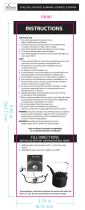
Placement of Standby Generating set to REDUCE THE RISK OF CARBON MONOXIDE
POISONING
The arrows in the figure below point to POTENTIAL points of entry for Carbon
Monoxide Gas.
A
F
C
D
B
E
G
F
C
D
B
E
G
NOTICE This Section is for Carbon Monoxide Hazard Safety Placement Only. Satisfying the standby generating
set placement, for the Carbon Monoxide hazard, does not guarantee that Fire Safety Placement requirements are
met. Please refer to Page 14 for Fire Hazard Safety Placement requirements.

Not for
Reproduction
13
• Direct the standby generating set exhaust away
from or parallel to the building or structure. DO
NOT direct the generating set exhaust towards a
potentially occupied building, structure, windows,
doors, ventilation intakes, soffit vents, crawl
spaces, open garage doors or other openings
where exhaust gas could accumulate and enter
inside or be drawn into potentially occupied
building or structure.
• DO NOT place standby generating set in any area
where leaves or debris normally accumulates.
Position standby generating set in an area where
winds will carry the exhaust gas away from any
potentially occupied building or structure.
Other General Location Guidelines
• Place the generating set in a prepared location
that is flat and has provisions for water drainage.
• Install the generating set in a location where sump
pump discharge, rain gutter downspouts, roof run-
off, landscape irrigation, or water sprinklers will
not flood the unit or spray the enclosure and enter
any air inlet or outlet openings.
• Install the generating set where it will not affect
or obstruct and services including covered,
concealed and underground, such as telephone,
electric, fuel (natural gas/ LPG vapor), irrigation,
air conditioning, cable, septic, sewer, well and so
forth.
• Install the generating set where leaves, grass,
snow, etc. will not obstruct air inlet and outlet
openings. If prevailing winds will cause blowing or
drifting, you may need to construct a windbreak to
protect the unit.
WARNING
Exhaust heat/gases could ignite
combustibles or structures resulting in death
or serious injury.
• Exhaust outlet side of weatherproof enclosure must
have at least 1.5 m minimum clearance from any
structure, shrubs, trees or any kind of vegetation.
• Generating set’s weatherproof enclosure must be at
least 1.5 m from windows, doors, any wall opening,
shrubs or vegetation over 30.5 cm in height.
• Generating set’s weatherproof enclosure must have
a minimum of 1.5 m overhead clearance from any
structure, overhang or trees.
• DO NOT place weatherproof enclosure under a
deck or other type of structure that may confine
airflow.
• Use only flexible fuel line provided. Connect
provided fuel line to generator, DO NOT use with or
substitute any other flexible fuel line.
• Smoke detector(s) MUST be installed and
maintained indoors according to the manufacturer’s
instructions/recommendations. Carbon monoxide
alarms cannot detect smoke.
• DO NOT place weatherproof enclosure in manner
other than shown in illustrations.
STANDBY
GENERATOR
ENGINE
EXHAUST

Not for
Reproduction
14
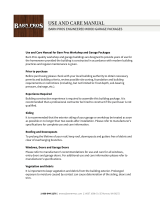
Examples of standby generating set locations to
reduce the risk of fire:
Vertical Clearances
Structure
Center of Exhaust Panel
Standby
Exhaust
Direction
1.5 m
1.5 m
B
C
B
C
Legend for Generating Set Locations to reduce
the risk of fire:
A - Generator set’s weatherproof enclosure must
be at least 1.5 m from windows, doors, any wall
opening, shrubs, or vegetation over 30.5 cm in
height.
B - Exhaust outlet side of weatherproof enclosure
must have at least 1.5 m minimum clearance from
any structure, overhang or trees.
C - Generating set’s weatherproof enclosure must
have a minimum of 1.5 m overhead clearance
from any structure, overhang, or trees.
NOTICE DO NOT place weatherproof enclosure under
a deck or other type of covered structure that may
confine airflow.

Not for
Reproduction
15
Generating Set Installations
A
A
A
A
A
A
A
Standby
Standby
Standby
Standby
1.5 m
1.5 m
1.5 m
1.5 m
1.5 m
1.5 m
1.5 m
Exhaust
Direction
Exhaust
Direction
Exhaust
Direction
Exhaust
Direction
45.7 cm min.45.7 cm min.
B
B
B
B
45.7 cm
NOTICE The figures below show the minimum installation distances allowed to structures and items listed in the
legend.
Legend for Generating Set Locations to reduce
the risk of fire:
A - Generator set’s weatherproof enclosure
must be at least 1.5 m from windows, doors,
any wall opening, shrubs, or vegetation over
30.5 cm in height.
B - Exhaust outlet side of weatherproof
enclosure must have at least 1.5 m minimum
clearance from any structure, overhang or
trees.
C - Generating set’s weatherproof enclosure must
have a minimum of 1.5 m overhead clearance from
any structure, overhang, or trees.
NOTICE DO NOT place weatherproof enclosure under a
deck or other type of covered structure that may confine
airflow.

Not for
Reproduction
16
Electrical and Fuel Inlet Locations
The 19 mm N.P.T. fuel inlet connector (A) and electrical
inlet location (B) is shown below.
A
B

Not for
Reproduction
17
Lifting the Generating Set
The generating set weighs more than 150 kg. Proper
tools, equipment and qualified personnel should
be used in all phases of handling and moving the
generating set.
Two 1.2 m lengths of size 6 scaffold tube (33.7 mm OD
x 25 mm ID to EN39) or equivalent are required to lift
the generating set (A). Insert these tubes through the
lifting holes (B) located near the unit’s base. Position
the tubes so that equal length’s protrude from each
side.
You may also lift the unit using a “hook and hoist”
method attached to the lifting pipes, provided that you
use a spreader bar to ensure that the chains or cables
DO NOT touch the generating set’s roof.
In areas determined to be hurricane prone, it is
recommended to anchor the standby generating set to
concrete. The concrete anchors must be rated to hold
800 lbs ( kg). There are three (C) locations in the base
of the generating set in which to anchor the unit.
Concrete Anchoring of Unit
NOTICE Unless mandated by code, a concrete
slab is not required.
C
C
C
A
B
WARNING Hazardous Voltage - Contact with
power lines could cause electric shock
or burns, resulting in death or serious
injury.
Lifting Hazard / Heavy Object - Could
result in serious injury.
• If lifting or hoisting equipment is used, DO NOT
contact any power lines.
• DO NOT lift or move generating set without
assistance.
• Use lifting pipes as described in Lifting the
Generating Set.
• DO NOT lift unit by roof as damage to generating
set will occur.

Not for
Reproduction
18
Access Ports
The generating set is equipped with an enclosure that
has several access panels, as shown.
NOTICE The generating set roof must be removed to
gain access to the front panel.
(A) Front Panel that is used to access:
• Battery Compartment
• Engine Oil Drain Hose
• Engine Oil Filter
• Engine Valve Cover
• Spark Plugs
Each generating set is shipped with a set of identical
keys.
A

Not for
Reproduction
19
To remove roof:
1. Remove the five screws (A) that secure the roof
to the unit.
2. Carefully lift and remove roof from unit.
To remove front panel:
1. Remove the two screws (B) that secure the panel to
the unit.
2. Lift and flex panel outward and off base. Use
caution not to damage the battery box (C).
To secure front panel:
1. Place panel in unit.
2. Secure the panel with two screws.
A
C
B

Not for
Reproduction
20
The Gaseous Fuel System
The information below is provided to assist
gaseous fuel system technicians in planning
installations. In no way should this information
be interpreted to override applicable fuel gas
codes. Consult with your local fuel supplier or Fire
Marshall if questions or problems arise.
TO THE INSTALLER: Consult with the generating
set owner(s) and convey any technical
considerations that might affect their installation
plans before applying these general guidelines.
The following general rules apply to gaseous fuel
system piping:
NOTICE The supplied flexible
steel fuel line
is not to be
installed underground or in contact with the ground.
• The entire
flexible
steel fuel line must be visible for
periodic inspection and must not be concealed
within nor contact nor run through any wall, floor,
or partition.
• The piping should be of a material that conforms
to federal and local codes, rigidly mounted and
protected against vibration.
• Piping should be protected from physical
damage where it passes through flower beds,
shrub beds, and other cultivated areas where
damage could occur.
NOTICE The illustration is representative of a typical
installation. Your installation may differ.
• Install the
flexible
steel fuel line (B) (supplied)
between the generating set fuel inlet port (A)
and rigid piping to prevent thermal expansion,
contraction, or any standby movement from
causing excessive stress on the piping material.
• A union (C) or flanged connection shall be
provided downstream to permit removal of
standby.
• A manometer port should be provided (D). A
digital manometer, P/N 19495, is available at
your Briggs & Stratton service center. When the
initial test runs are completed, the manometer
is removed and the port is plugged. The
manometer port permits temporary installation of
a manometer to ensure that the engine receives
the correct fuel pressure to operate efficiently
throughout its operating range.
• Where the formation of hydrates or ice is known
to occur, piping should be protected against
freezing. The termination of hard piping should
include a sediment trap (F) where condensate is
not likely to freeze.
• A minimum of one accessible, approved manual
shutoff valve (E) shall be installed in the fuel
supply line within 180 cm of the generating set.
• A manual fuel shut-off valve should be installed
in the interior of the building.
• Where local conditions include earthquake,
tornado, unstable ground, or flood hazards,
special consideration shall be given to increase
strength and flexibility of piping supports and
connections.
• Piping must be of the correct size to maintain
the required supply pressures and volume flow
under varying generating set load conditions
with all gas appliances connected to the fuel
system turned on and operating.
• Apply thread sealant approved for use with NG/
LPG on all male threads only per sealant
manufacturer’s instructions and applicable
codes and standards.
NOTICE Keep thread sealant out of the gas
piping to prevent component part damage.
• Installed piping must be properly purged and
leak tested, in accordance with applicable codes
and standards.
WARNING
Propane and Natural Gas are
extremely flammable and explosive,
which could cause burns, fire or
explosion resulting in death or serious
injury.
• LP gas is heavier than air and will settle in low
areas.
• Natural gas is lighter than air and will collect in high
areas.
• The slightest spark could ignite these fuels and
cause an explosion.
• DO NOT light a cigarette or smoke.
WARNING Propane and Natural Gas are
extremely flammable and explosive,
which could cause burns, fire or
explosion resulting in death or serious
injury.
• Before placing the generating set into service, the
fuel system lines must be properly purged and leak
tested.
• No leakage is permitted.
D
A
F
E
B
C
/