Page is loading ...

4x4/8x8 4K/18G HDMI Matrix Switchers,
with Independent Audio Switching,
Balanced/Unbalanced Audio,
Audio De-embedding of Analog L/R/PCM
Operating Instructions
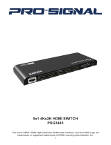
KD-MS4x4G
KD-MS8x8G
KD-MS4x4G
KD-MS8x8G
Default static IP address:
192.168.1.239, port 23

2
Table of Contents
About KD-MS4x4G/KD-MS8x8G ............................................... 1
Application Example ......................................................... 2
Quick Setup Guide .......................................................... 3
Connections, Buttons and LEDs ................................................ 4
Settings and Adjustments via Remote ............................................ 7
Basic configuration via Key Digital Management Software
™
Pro (KDMS
™
Pro).............. 9
RS-232 and TCP/IP Commands . . . . . . . . . . . . . . . . . . . . . . . . . . . . . . . . . . . . . . . . . . . . . . . 12
Specifications ............................................................. 16
Important Product Warnings .................................................. 17
Safety Instructions .......................................................... 17
Power Supply Use.......................................................... 17
How to Contact Key Digital ................................................... 18
Warranty Information ........................................................ 19
› Note: Please visit www.keydigital.com for the latest product documentation and software
downloads. Product features and specifications are subject to change without notice.
© 2018 Key Digital, Inc. All rights reserved.
Always follow the instructions provided in this Operating Manual.
KD-MS4x4G KD-MS8x8G
Visit product pages for most recent version
of the manual, quick setup guide, firmware,
control drivers and all additional downloads.

1
About KD-MS4x4G/KD-MS8x8G
Key Digital’s KD-MS4x4G and KD-MS8x8G are 4K matrix switchers with support of 18Gbps signal
bandwidth and HDCP 2.2 for routing and distributing 4/8 HDMI source signals to 4/8 displays. KD-
MS4x4G and KD-MS8x8G feature 4/8 analog and digital audio outputs which may be independently
controlled to follow the HDMI output selection or separately switched to accommodate a wide
variety of usage applications in professional AV systems integration. KD-MS4x4G/KD-MS8x8G
supports all SD, HD, VESA and Ultra HD/4K video standards up to and including UHD/4K 18G and
1080p. All UHD/4K EDID handshake files include HDR header information.
Key Features
› HDMI Matrix Switching: 4/8 HDMI sources to 4/8 HDMI outputs
› Ultra HD/4K Support: 4096x2160 or 3840x2160 24/25/30/60hz at 4:4:4 (signals up to
18Gbps bandwidth)
› HDCP Licensing: Fully licensed and compatible with HDCP 2.2
› HDR10 (High Dynamic Range): More life-like images through a greater range
of luminance levels
› Resolution Support: Supports all SD, HD, and VESA (VGA, SVGA, XGA, WXGA, SXGA,
UXGA) up to 4096x2160p
› Deep Color Support: Up to UHD/4K 60Hz 4:2:0/12 bits, 60Hz 4:2:2/12 bits
› Independent Audio and Video Matrix: Output HDMI and Audio ports may switch together
or independently
› Full Buffer System
™
: Manages TMDS re-clocking / signal re-generation, HDCP
authentication to source & display, and EDID Control handshake
› EDID: Internal library with 15 internal EDID configurations per input, in addition to native
EDID data for any Output/Display
› TMDS re-clocking: Support for long HDMI connectivity using Key Digital
®
HDMI cables
› Lossless Compressed Digital Audio: Dolby
®
TrueHD, Dolby
®
Digital Plus, DTS-HD Master
Audio
™
, and Dolby
®
Atmos
› Control: Front panel buttons/LEDs, Serial IR, Optical IR, RS-232 Control, and TCP/IP Control
› Control System Support: Key Digital
®
app ready. Key Digital Management Software
™
Pro
(KDMS
™
Pro) ready, Compass Control
®
Pro ready. Fully controllable by all IR, RS-232, and
TCP/IP supported control systems via open API.
› Key Digital
®
App & KDMS
®
Pro Ready: Scan & detect population for pre-built GUI
and TCP/IP control via Key Digital
®
App and Key Digital Management Software
™
Pro
(KDMS
™
Pro) PC Software
Accessories
› Power Supply:
KD-PS40W12VD 12V/3.3A (40W) DC Power Jack, Screw In Type
› Rack Ears
› KD-RMSWPROK Remote Control
› 6-Pin Terminal Blocks : KD-MS4x4G - Qty 5 / KD-MS8x8G - Qty 9
Rack Mounting:
› Secure the rack ears to each side of the KD-MS4x4G/KD-MS8x8G with the supplied hardware
and then fasten the unit to the rack rails with the included machine screws.

2
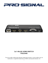
Application Example
Projector
Visualizer
Laptop
Networked PCs
Ultra HD/4K
Digital Signage
HDMI
HDMI
HDMI
RS-232
RS-232
HDMI
HDMI
IR/RS232
HDMI
HDMI
HDMI
IR
WiFi Router
RJ45
RJ45
WiFi
x3
Main Room Wall
Displays
Displays
Operation CenterHuddle Room
Audio
HDMI
HDMI
Technical Support:
email: [email protected]
phone: 914.667.9700 ext 3
www.keydigital.com/compass
Compass Control
®
Pro Site
521 East 3rd Street • Mount Vernon • NY 10553
phone: 914.667.9700
• fax: 914.668.8666
Enterprise Software License
for Compass Control
®
Pro
Supports iOS & Android
KD-ProCL8
KD-ProCL6
KD-ProCL4
KD-ProCL1
KD-ProCL1
x2
KD-MC1000
Master Controller
x4
KD-MS8x8G
x3
KD-AMP220
Input Control
Vol
Mic
Mute
Line BassL/R PCM
1
2
Treble
KD-AMP220
Input Control
Vol
Mic
Mute
Line BassL/R PCM
1
2
Treble
KD-AMP220
Input Control
Vol
Mic
Mute
Line BassL/R PCM
1
2
Treble
KD-AMP220
CAT5e/6
x5
KD-X444L Tx
IR
HDMI
KD-X444L Rx
IR
HDMI
KD-X444L Rx

3
Quick Setup Guide
Test for proper operation of the unit and cables in your system before permanently securing the unit
for final installation. Ensure that you leave enough ventilation space to provide sufficient airflow and
cooling.
1. Begin with the KD-MS4x4G/KD-MS8x8G unit and all input/output devices turned off with
power cables removed
2. Connect your HDMI sources to the input ports of KD-MS4x4G/KD-MS8x8G unit
3. Connect your HDMI displays to the output ports of KD-MS4x4G/KD-MS8x8G unit
4.
Before
connecting power supply to power outlet, screw-in the power supply to the KD-
MS4x4G/KD-MS8x8G unit
5. Connect the analog audio outputs to amplifiers/receivers via the analog 6-pin phoenix
terminals and digital destinations via the PCM outputs
6. After all connections are made, plug-in power supply to power outlet
7. Power on input/output devices
8. Operate the KD-MS4x4G/KD-MS8x8G switcher via front panel buttons, IR Remote, Serial
IR, RS-232, or TCP/IP control, including
Key Digital
®
App and Key Digital Management
Software
®
Pro (KDMS
™
Pro) PC Software
9. See TCP/IP and RS-232 Command or Settings and Adjustments via Remote sections for
more adjustments options
Default static IP address:
192.168.1.239, port 23

4
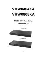
Connections, Buttons and LEDs
HDMI Inputs and Outputs
HDMI Inputs & LEDs HDMI Outputs & LEDs
Serial IR
& RS-232
TCP/IP
Power
Audio Outputs - PCM and 6-Pin Terminal Block
› HDMI Inputs:
» The HDMI Inputs are located on the bottom left side of the back panel.
» The Inputs have a blue LED that will illuminate solid to indicate an active HDMI signal is
incoming.
› HDMI Outputs:
» The HDMI Outputs are located on the bottom right side of the back panel.
» The Outputs have a blue LED that will illuminate solid when receiving an active Hot Plug
Detection (HDMI voltage) from the connect display/sync device.
» HDMI outputs may switch to select HDMI sources independently or together with the
respective audio outputs.
› HDMI Input/Output Port Specifications
» Supports up to UHD/4K @ 50/60 fps [4:4:4], 18Gbps signals
» See Supported standard 4K Video Formats table
» Supports HDR10
» Compliant with HDCP 2.2 and previous
» Supports lossless compressed audio formats including Dolby
®
TrueHD, Dolby
®
Digital Plus,
Dolby Atmos
®
, and DTS-HD Master Audio
™
» Does not support CEC
» For DVI-D/DVI-I sources or monitors, use appropriate adapters. For Display Port, use active
converters
Supported standard 4K Video Formats:
Resolution Bandwidth
1 4K@24/25/30 [4:4:4] 8bit < 10.2Gbps
2 4K@24/25/30 [4:2:2] 8/10/12bit < 10.2Gbps
3 4K@50/60 [4:2:0] 8bit < 10.2Gbps
4 4K@24/25/30 [4:4:4] 10/12bit < 18Gbps
5 4K@50/60 [4:2:2] 8/10/12bit < 18Gbps
6 4K@50/60 [4:2:0] 10/12bit < 18Gbps
7 4K@50/60 [4:4:4] 8bit < 18Gbps

5
Audio Outputs
Pin: 1 2 3 4 5 6
› Analog Audio Outputs: Each Output Channel has 1 Analog L/R Balanced/Unbalanced 6-Pin
Terminal Block which provides de-embedded 2ch Balanced Analog Audio Output from the
selected HDMI input source
› The Pin assignment for the audio is as follows:
» Left + is Pin 1; Left - is Pin 3; Left Ground is Pin 2.
» Right + is Pin 4; Right - is Pin 6; Right Ground is Pin 5.
› Digital Audio Outputs: Each Output Channel has 1 Digital Audio RCA output port which provides
de-embedded Digital Audio Output from selected HDMI input
› Compatible with SPDIF format IEC 60958 supporting 2ch PC, Dolby 5.1ch, DTC 6.1ch
› Compatible with sampling rates up to 192KHz
› Audio outputs may switch to select HDMI audio sources independently or together with the
respective HDMI outputs.
› Each output drives audio signals up to 2VRMS with a sampling rate of 192KHz
› There are no volume or tone control features, only muting control of the external audio outputs via
RS-232 and TCP/IP
› There are no DSP features. Audio must be configured in the source. For example, in order to
achieve 2ch analog audio output, the selected HDMI input source audio format must be 2ch.
Audio Input
Signal Format
Audio L/R
Output
Digital Audio Output
(Coax and Optical)
2ch PCM Pass-Through Pass-Though
Multi-Channel PCM MUTE MUTE
Dolby DTS MUTE Pass-Though
HD Audio MUTE MUTE

6
Unit Control Ports
Pin: 1 2 3 4 5 6
› MAIN Control Port
» 6-Pin Terminal Block for IR and RS-232
» RS-232 and TCP/IP commands may be found in the RS-232 & TCP/IP Commands section
» Pin out:
» Pin 1 = Serial (Wired) IR In
» Pin 2 = IR Ground
» Pin 3 = RS-232 Tx Data
» Pin 4 = RS-232 Ground
» Ping 5 = RS-232Rx Data
» Pin 6 = Ground (optional)
› MAIN Control Port
» Default static IP address is 192.168.1.239, port 23
» Connect an Ethernet cable from the KD-MS4x4G/KD-MS8x8G to a network router or
connect a straight through cable directly from a PC
» Unit configuration, control, and firmware updates are most commonly achieved with
Key Digital Management Software
™
Pro (KDMS
™
Pro)
downloaded HERE.
Front Buttons and LEDs
IR Eye
Input LEDs
Output Select Buttons
› Pressing an output button will select the next HDMI input.
› A blue LED will indicate which Input has been selected for each Output.
› Front button control can be disabled/enabled via serial control if desired.
› Press and hold Output 1 + Output 4 buttons simultaneously for 10 seconds to reset the unit to
factory default.
› Notes:
» Front LEDs will scroll during boot up
» Output OFF setting for an output is represented by a illumination of the middle LEDs
(KD-MS4x4G - lights 2 and 3; KD-MS8x8G - lights 3,4,5,6) for the respective output
Default static IP address:
192.168.1.239, port 23

7
Settings and Adjustments via Remote
Many initial installation steps may be configured using the factory remote control.
Other advanced settings may be configured using TCP/IP or RS-232 and via
Key Digital
Management Software
™
Pro (KDMS
™
Pro)
downloaded HERE.
› Matrix Switching – Video and Audio together
» IR Button Sequence =
X, Y
» X = Output # [1-8]
» Y = Input # [1-8]
› Matrix Switching – Video ONLY
» IR Button Sequence =
R1, X, Y
» X = Output # [1-8]
» Y = Input # [1-8]
› Matrix Switching – Audio ONLY
» IR Button Sequence =
R2, X, Y
» X = Output # [1-8]
» Y = Input # [1-8]
› EDID Handshake to Input from Unit’s EDID Table
» IR Button Sequence =
R2, R1, R3, Y, ZZ
» Y = Input # [1-8]
» ZZ = Device Select # [01-15]
Unit’s EDID Table (7 is the default)
01 1080i, 2CH AUDIO
02 1080i, DOLBY/DTS 5.1
03 1080i, HD AUDIO
04 1080p, 2CH AUDIO
05 1080p, DOLBY/DTS 5.1
06 1080p, HD AUDIO
07 4Kx2K@60, 10.2G, HDR, 2CH AUDIO
08 4Kx2K@60, 10.2G, HDR, DOLBY/DTS 5.1
09 4Kx2K@60, 10.2G, HDR, HD AUDIO
10 4Kx2K@60, 18G, HDR, 2CH AUDIO
11 4Kx2K@60, 18G, HDR, DOLBY/DTS 5.1
12 4Kx2K@60, 18G, HDR, HD AUDIO
13 1280x720p@60 DVI (no audio)
14 1920x1080p@60 DVI (no audio)
15 4Kx2K@30, 10.2G, HDR, 2CH AUDIO

8
› EDID Handshake to Input from Connected Output
» IR Button Sequence =
R2, R1, R3, Y, X
» Y = Input # [1-8]
» X = Output # [1-8]
› Set Output Debug Mode
» IR Button Sequence =
R3, R2, R1, X, Z
» X = Output # [1-8]
» Z = 1 (On) / 0 (Off)

9
Basic configuration via Key Digital
Management Software
™
Pro (KDMS
™
Pro)
KDMS
™
Pro Download Page
About KDMS Pro
Key Digital Management Software
™
Pro (KDMS
™
Pro) may be
downloaded at www.keydigital.com/KDMS-Pro.html and used to
configure and control your KD-MS4x4G/KD-MS8x8G as well as other
KDMS Pro compatible devices/systems. An end-user friendly version
which only offers control of the unit after configuration is completed is
also available at www.keydigital.com/KDMS-User.html.
Connection
Connecting to KD-MS4x4G/KD-MS8x8G is done via the unit’s TCP/IP port using the unit’s
default IP address 192.168.1.239. Connect KD-MS4x4G/KD-MS8x8G to a 192.168.1.xxx type
network or set your PC to a static IP address of 192.168.1.xxx (excluding .239).
Default static IP address:
192.168.1.239, port 23
› 1. Connect to your unit as instructed above
› 2. Open the KDMS Pro software and perform a network scan (fig. 1)

10
› 3. Choose the detected device from the Devices window (fig. 2a)
› 4. In the Network Settings section of the Properties window, enter the desired IP settings (fig. 2b)
» a. IP Address (default is 192.168.1.239)
» b. Subnet Mask (default is 255.255.255.0)
» c. Gateway (default is 192.168.1.1)
» d. Port (default is 23)
› 5. Save (fig. 2c)
› 6. In the EDID Settings section, choose the desired handshake that you wish to provide to your
connected HDMI source (fig 3a).

11
› 7. If using KD-App or KDMS for control , set the desired Input/Output names by entering the
Input/Output Settings section of the properties window, and selecting the Change Input/Output
Name button (fig. 4a), selecting the desired input/output and entering the name (fig. 4b)
› 8. Additional settings may be adjusted in the KDMS software. Full access to all settings/
commands is achieved via terminal session using Tera Term or PuTTy software.
› 9. Your unit is now ready to control from the KDMS
™
Control Panel, KD-App, or by professional
control system.

12
RS-232 and TCP/IP Commands
KD-MS4x4G/KD-MS8x8G allows control over serial interface for bi-directional communication.
Pin: 1 2 3 4 5 6
Use pins 3, 4, and 5 for RS-232 communication.
In addition to RS-232, the serial interface may also be accessed using a TCP/IP connection
› Default IP address is 192.168.1.239, with default port 23
Connection Protocol:
» Baud Rate = 57,600 bits per second
» Data Bits = 8
» Stop Bits = 1
» Parity = Non
» Flow Control = None
» Carriage Return: Required at end of string
› Notes:
» Commands are not case-sensitive
» Spaces are shown for clarity; commands should NOT have any spaces
» After a new command is received, a prompt should be sent back
KD-MS4x4G Help Command (H). Returns entire API in readable format:
-------------------------------------------------------------------------
-- Key Digital Systems HELP --
-------------------------------------------------------------------------
-- KD-MS4x4G System Address = 00 F/W Version : 2.05 --
-- --
-- Azz : All Commands may have Prex System Address zz=[01-99] --
-- H : Help --
-- PF : Power Off --
-- PN : Power ON --
-- STA : Show Global System Status --
-- --
-- HDMI Output Setup Commands: --
-- ( xx = [01-04,A], yy = [01-04,U/D], A=All, U=Up, D=Down ) --
-- SPO xx SI yy : Set Both HDMI and Audio Output xx to HDMI Input yy --
-- SPO xx SB yy : Set HDMI Output xx to HDMI Input yy --
-- SPO xx ON/OFF : Set Output xx ON/OFF --
-- SPO xx DBG ON/OFF : Set Output xx Debug Mode ON/OFF --
-- --
-- Audio Output Setup Commands: [E=Enable, D=Disable] --
-- ( xx = [01-04,A], yy = [01-04,U/D], A=All, U=Up, D=Down ) --
-- SPO xx SA yy : Set Audio Output xx to HDMI Input yy --
-- SPO xx AA E/D : Enable/Disable External Analog Audio Output --
-- SPO xx DA E/D : Enable/Disable External Digital Audio Output --
-- --
Default static IP address:
192.168.1.239, port 23

13
-- Input/Output/Device Naming Commands (Max. 16 Chars) --
-- SPI xx WN cccccccccccccccc : Write Input xx Name --
-- SPI xx RN : Read Input xx Name --
-- SPO xx WN cccccccccccccccc : Write Output xx Name --
-- SPO xx RN : Read Output xx Name --
-- SPC WN cccccccccccccccc : Write Device Name --
-- SPC RN : Read Device Name --
-- --
-- EDID Setup, xx = [01-04,A], yy = [01-04], zz = [01-15] (A=All) --
-- SPC EDID xx H yy : Copy EDID from Ouput yy to Input xx --
-- SPC EDID xx D zz : Copy EDID from Default EDID zz to Input xx --
-- DEFAULT EDID 01 : HDMI 1080i@60, Audio 2CH PCM --
-- DEFAULT EDID 02 : HDMI 1080i@60, Audio PCM,DTS/DOLBY --
-- DEFAULT EDID 03 : HDMI 1080i@60, Audio PCM,DTS/DOLBY/HD --
-- DEFAULT EDID 04 : HDMI 1080p@60, Audio 2CH PCM --
-- DEFAULT EDID 05 : HDMI 1080p@60, Audio PCM,DTS/DOLBY --
-- DEFAULT EDID 06 : HDMI 1080p@60, Audio PCM,DTS/DOLBY/HD --
-- DEFAULT EDID 07 : HDMI 4Kx2K@60/3D/HDR10/10G, 2CH PCM --
-- DEFAULT EDID 08 : HDMI 4Kx2K@60/3D/HDR10/10G, PCM,DTS/DOLBY --
-- DEFAULT EDID 09 : HDMI 4Kx2K@60/3D/HDR10/10G, PCM,DTS/DOLBY/HD --
-- DEFAULT EDID 10 : HDMI 4Kx2K@60/3D/HDR10/18G, 2CH PCM --
-- DEFAULT EDID 11 : HDMI 4Kx2K@60/3D/HDR10/18G, PCM,DTS/DOLBY --
-- DEFAULT EDID 12 : HDMI 4Kx2K@60/3D/HDR10/18G, PCM,DTS/DOLBY/HD --
-- DEFAULT EDID 13 : DVI Video Max. 1280x720@60, No Audio --
-- DEFAULT EDID 14 : DVI Video Max. 1920x1080@60, No Audio --
-- DEFAULT EDID 15 : HDMI 4Kx2K@30/3D/HDR10/10G, 2CH PCM --
-- --
-- Network Setup, ( xxx=[000-255], zzzz=[0023~9999] ) --
-- SPCETIPA xxx.xxx.xxx.xxx : Set Host IP Address to xxx.xxx.xxx.xxx --
-- SPCETIPM xxx.xxx.xxx.xxx : Set Net Mask to xxx.xxx.xxx.xxx --
-- SPCETIPR xxx.xxx.xxx.xxx : Set Route IP Address to xxx.xxx.xxx.xxx --
-- SPCETIPP zzzz : Set TCP/IP Port to zzzz --
-- SPCETIPB : Apply New Network Cong --
-- --
-- System Address Setup Command: xx = [00-99], 00 = Single --
-- SPC Axx : Set System Address to xx --
-- --
-- System Control Setup Commands: --
-- SPC RSB z : Set RS232 Baud Rate to z bps, z=[0-4] --
-- [0:57600, 1:38400, 2:19200, 3:9600, 4:4800] --
-- SPC FB E/D : Enable/Disable Front Panel Buttons --
-- SPC DF : Reset to Factory Defaults with DEFAULT EDID 10 --
-------------------------------------------------------------------------
KD-MS4x4G Status command (STA). Returns current state and settings of the unit:
-------------------------------------------------------------------------
-- Key Digital Systems STATUS --
-------------------------------------------------------------------------
-- Model: KD-MS4x4G, System Address = 00, Device Name: KD-MS4x4G --
-- Main F/W Ver: 2.05, I/O F/W Ver: 5.16, IPM F/W Ver: 6.44 --
-- --
-- Power : ON --
-- RS232 : Baud Rate=57600bps, Data=8bit, Parity=None, Stop=1bit --
-- Front Panel Button : Enabled --
-- --
-- Network Setting(Telnet Server) Status --
-- MAC Address = 60:89:B1:22:20:03 --
-- Host IP Address = 192.168.001.239 --
-- Net Mask = 255.255.255.000 --
-- Router IP Address = 192.168.001.001 --
-- TCP Port = 0023 --
-- --

14
-- HDMI Input 01 : EDID = DEFAULT 10, LINK = ON --
-- HDMI Input 02 : EDID = DEFAULT 10, LINK = ON --
-- HDMI Input 03 : EDID = DEFAULT 10, LINK = ON --
-- HDMI Input 04 : EDID = DEFAULT 10, LINK = ON --
-- --
-- HDMI Output 01 : IN = 01, OUT = ON , LINK = ON , DBG = OFF, --
-- HDMI Output 02 : IN = 02, OUT = ON , LINK = ON , DBG = OFF, --
-- HDMI Output 03 : IN = 03, OUT = ON , LINK = ON , DBG = OFF, --
-- HDMI Output 04 : IN = 04, OUT = ON , LINK = ON , DBG = OFF, --
-- --
-- Audio Output 01 : IN = 01, Balanced = Enabled, PCM = Enabled --
-- Audio Output 02 : IN = 02, Balanced = Enabled, PCM = Enabled --
-- Audio Output 03 : IN = 03, Balanced = Enabled, PCM = Enabled --
-- Audio Output 04 : IN = 04, Balanced = Enabled, PCM = Enabled --
-------------------------------------------------------------------------
KD-MS8x8G Help Command (H). Returns entire API in readable format:
-------------------------------------------------------------------------
-- Key Digital Systems HELP --
-------------------------------------------------------------------------
-- KD-MS8x8G System Address = 00 F/W Version : 2.06 --
-- --
-- Azz : All Commands may have Prex System Address zz=[01-99] --
-- H : Help --
-- PF : Power Off --
-- PN : Power ON --
-- STA : Show Global System Status --
-- --
-- HDMI Output Setup Commands: --
-- ( xx = [01-08,A], yy = [01-08,U/D], A=All, U=Up, D=Down ) --
-- SPO xx SI yy : Set Both HDMI and Audio Output xx to HDMI Input yy --
-- SPO xx SB yy : Set HDMI Output xx to HDMI Input yy --
-- SPO xx ON/OFF : Set Output xx ON/OFF --
-- SPO xx DBG ON/OFF : Set Output xx Debug Mode ON/OFF --
-- --
-- Audio Output Setup Commands: [E=Enable, D=Disable] --
-- ( xx = [01-08,A], yy = [01-08,U/D], A=All, U=Up, D=Down ) --
-- SPO xx SA yy : Set Audio Output xx to HDMI Input yy --
-- SPO xx AA E/D : Enable/Disable External Analog Audio Output --
-- SPO xx DA E/D : Enable/Disable External Digital Audio Output --
-- --
-- Input/Output/Device Naming Commands (Max. 16 Chars) --
-- SPI xx WN cccccccccccccccc : Write Input xx Name --
-- SPI xx RN : Read Input xx Name --
-- SPO xx WN cccccccccccccccc : Write Output xx Name --
-- SPO xx RN : Read Output xx Name --
-- SPC WN cccccccccccccccc : Write Device Name --
-- SPC RN : Read Device Name --
-- --
-- EDID Setup, xx = [01-08,A], yy = [01-08], zz = [01-15] (A=All) --
-- SPC EDID xx H yy : Copy EDID from Ouput yy to Input xx --
-- SPC EDID xx D zz : Copy EDID from Default EDID zz to Input xx --
-- DEFAULT EDID 01 : HDMI 1080i@60, Audio 2CH PCM --
-- DEFAULT EDID 02 : HDMI 1080i@60, Audio PCM,DTS/DOLBY --
-- DEFAULT EDID 03 : HDMI 1080i@60, Audio PCM,DTS/DOLBY/HD --
-- DEFAULT EDID 04 : HDMI 1080p@60, Audio 2CH PCM --
-- DEFAULT EDID 05 : HDMI 1080p@60, Audio PCM,DTS/DOLBY --
-- DEFAULT EDID 06 : HDMI 1080p@60, Audio PCM,DTS/DOLBY/HD --
-- DEFAULT EDID 07 : HDMI 4Kx2K@60/3D/HDR10/10G, 2CH PCM Audio --
-- DEFAULT EDID 08 : HDMI 4Kx2K@60/3D/HDR10/10G, PCM,DTS/DOLBY --
-- DEFAULT EDID 09 : HDMI 4Kx2K@60/3D/HDR10/10G, PCM,DTS/DOLBY/HD --
-- DEFAULT EDID 10 : HDMI 4Kx2K@60/3D/HDR10/18G, 2CH PCM Audio --
-- DEFAULT EDID 11 : HDMI 4Kx2K@60/3D/HDR10/18G, PCM,DTS/DOLBY --
-- DEFAULT EDID 12 : HDMI 4Kx2K@60/3D/HDR10/18G, PCM,DTS/DOLBY/HD --
-- DEFAULT EDID 13 : DVI Video Max. 1280x720@60, No Audio --

15
-- DEFAULT EDID 14 : DVI Video Max. 1920x1080@60, No Audio --
-- DEFAULT EDID 15 : HDMI 4Kx2K@30/3D/HDR10/10G, 2CH PCM Audio --
-- --
-- Network Setup, ( xxx=[000-255], zzzz=[0023~9999] ) --
-- SPCETIPA xxx.xxx.xxx.xxx : Set Host IP Address to xxx.xxx.xxx.xxx --
-- SPCETIPM xxx.xxx.xxx.xxx : Set Net Mask to xxx.xxx.xxx.xxx --
-- SPCETIPR xxx.xxx.xxx.xxx : Set Route IP Address to xxx.xxx.xxx.xxx --
-- SPCETIPP zzzz : Set TCP/IP Port to zzzz --
-- SPCETIPB : Apply New Network Cong --
-- --
-- System Address Setup Command: xx = [00-99], 00 = Single --
-- SPC Axx : Set System Address to xx --
-- --
-- System Control Setup Commands: --
-- SPC RSB z : Set RS232 Baud Rate to z bps, z=[0-4] --
-- [0:57600, 1:38400, 2:19200, 3:9600, 4:4800] --
-- SPC FB E/D : Enable/Disable Front Panel Buttons --
-- SPC DF : Reset to Factory Defaults with DEFAULT EDID 10 --
-------------------------------------------------------------------------
KD-MS8x8G Status command (STA). Returns current state and settings of the unit:
-------------------------------------------------------------------------
-- Key Digital Systems STATUS --
-------------------------------------------------------------------------
-- Model: KD-MS8x8G, System Address = 00, Device Name: KD-MS8x8G --
-- Main F/W Ver: 2.06, I/O F/W Ver: 5.16, IPM F/W Ver: 6.44 --
-- --
-- Power : ON --
-- RS232 : Baud Rate=57600bps, Data=8bit, Parity=None, Stop=1bit --
-- Front Panel Button : Enabled --
-- --
-- Network Setting(Telnet Server) Status --
-- MAC Address = 60:89:B1:22:20:07 --
-- Host IP Address = 192.168.001.239 --
-- Net Mask = 255.255.255.000 --
-- Router IP Address = 192.168.001.001 --
-- TCP Port = 0023 --
-- --
-- HDMI Input 01 : EDID = DEFAULT 10, LINK = ON --
-- HDMI Input 02 : EDID = DEFAULT 10, LINK = ON --
-- HDMI Input 03 : EDID = DEFAULT 10, LINK = ON --
-- HDMI Input 04 : EDID = DEFAULT 10, LINK = ON --
-- HDMI Input 05 : EDID = DEFAULT 10, LINK = ON --
-- HDMI Input 06 : EDID = DEFAULT 10, LINK = ON --
-- HDMI Input 07 : EDID = DEFAULT 10, LINK = ON --
-- HDMI Input 08 : EDID = DEFAULT 10, LINK = ON --
-- --
-- HDMI Output 01 : IN = 08, OUT = ON , LINK = ON , DBG = OFF, --
-- HDMI Output 02 : IN = 08, OUT = ON , LINK = ON , DBG = OFF, --
-- HDMI Output 03 : IN = 08, OUT = ON , LINK = ON , DBG = OFF, --
-- HDMI Output 04 : IN = 08, OUT = ON , LINK = ON , DBG = OFF, --
-- HDMI Output 05 : IN = 08, OUT = ON , LINK = ON , DBG = OFF, --
-- HDMI Output 06 : IN = 08, OUT = ON , LINK = ON , DBG = OFF, --
-- HDMI Output 07 : IN = 08, OUT = ON , LINK = ON , DBG = OFF, --
-- HDMI Output 08 : IN = 08, OUT = ON , LINK = ON , DBG = OFF, --
-- --
-- Audio Output 01 : IN = 08, Balanced = Enabled , PCM = Enabled --
-- Audio Output 02 : IN = 08, Balanced = Enabled , PCM = Enabled --
-- Audio Output 03 : IN = 08, Balanced = Enabled , PCM = Enabled --
-- Audio Output 04 : IN = 08, Balanced = Enabled , PCM = Enabled --
-- Audio Output 05 : IN = 08, Balanced = Enabled , PCM = Enabled --
-- Audio Output 06 : IN = 08, Balanced = Enabled , PCM = Enabled --
-- Audio Output 07 : IN = 08, Balanced = Enabled , PCM = Enabled --
-- Audio Output 08 : IN = 08, Balanced = Enabled , PCM = Enabled --
-------------------------------------------------------------------------

16
Specifications
Technical:
› Input (Each): 1 HDMI Connector, Type A, 19 Pin Female
› Output (Each): 1 HDMI Connector, Type A, 19 Pin Female
› Output (Each): Balanced/unbalanced line level audio on 6-pin terminal block. Drives 2VRMS line
audio input with a sampling rate of 192KHz
› Output (each): RCA female for digital audio following SPDIF format (IEC 60958). Supports
sampling rate up to 192KHz
› Video Bandwidth: TMDS bandwidth 10.2 Gbps
› DDC Signal (Data): Input DDC Signal - 5 Volts p-p (TTL)
› HDMI Video/Audio Signal: Input Video Signal - 1.2 Volts p-p
› DDC Communication: EDID and HDCP Bi-directional buffering to Display and Source
› K-Factor: 0.22% @ optimal EQ » Video Isolation (Crosstalk): -45dB @ 5MHz
› Analog Audio Max Output Level: 4dBu on 150kΩ, DC coupling
› Audio Bandwidth: 20Hz to 20kHz @ 0dBu
› TND + Noise: 0.33% @0dBu @ 1kHz » PCM Max Input Level: 1Vpp on 75Ω, AC coupling
› PCM Max Output Level: 1Vpp on 75Ω, DC coupling
› Wired IR: modulated IR signal input, 0-5V TTL or -10 to +10V
› Power: 12V/3.3A (40W) AC Power Supply with Grounded, 2.1mm ID DC Power Jack with
Screw In Type.
General:
› Regulation: CE, RoHS, WEEE
› Rack Mount: 1U, 1 Rack Width (rack ears included)
› Enclosure: Black Metal
› KD-MS4x4G Dimensions: L = 17.32” W = 5.78” H = 1.72”
› KD-MS8x8G Dimensions: L = 17.32” W = 7.27” H = 1.72”
› Shipping Carton Dimensions: L = 23.4” W = 8.54” H = 2.36”
› Product Weight: 6 lb
› Shipping Weight: 9
› Accessories: IR Remote, UL Certified Power Supply

17
Important Product Warnings:
1. Connect all cables before providing power to the unit.
2. Test for proper operation before securing unit behind walls or in hard to access spaces.
3. If installing the unit into wall or mounting bracket into sheet-rock, provide proper screw support
with bolts or sheet-rock anchors.
Safety Instructions:
Please be sure to follow these instructions for safe operation of your unit.
1. Read and follow all instructions.
2. Heed all warnings.
3. Do not use this device near water.
4. Clean only with dry cloth.
5. Install in accordance with the manufacturer’s instructions.
6. Do not install near any heat sources such as radiators, heat registers, stoves, or other
apparatus (including amplifiers) that produce heat.
7. Only use attachments/accessories specified by the manufacturer.
8. Refer all servicing to qualified service personnel. Servicing is required when the device has
been damaged in any way including:
» Damage to the power supply or power plug
» Exposure to rain or moisture
Power Supply Use:
You MUST use the Power Supply provided with your unit or you VOID the
Key Digital
®
Warranty and risk damage to your unit and associated equipment.

18
How to Contact Key Digital
®
System Design Group (SDG)
For system design questions please contact us at:
› Phone: 914-667-9700
› E-mail: [email protected]
Customer Support
For customer support questions please contact us at:
› Phone: 914-667-9700
› E-mail: [email protected]
Technical Support
For technical questions about using Key Digital
®
products, please contact us at:
› Phone: 914-667-9700
› E-mail: [email protected]
Repairs and Warranty Service
Should your product require warranty service or repair, please obtain a
Key Digital
®
Return Material Authorization (RMA) number by contacting us at:
› Phone: 914-667-9700
› E-mail: [email protected]
Feedback
Please email any comments/questions about the manual to:
› E-mail: [email protected]
/