Yardworks 060-1300-6 User manual
- Category
- Mini tillers
- Type
- User manual
This manual is also suitable for

model number 060-1300-6 | contact us: 1.866.523.5218
IMPORTANT:
Read and follow all safety rules and operating
instructions before using this product.
Instruction
Manual
Rear Tine Tiller

model no. 060-1300-6 | contact us: 1.866.523.5218
2
TABLE OF CONTENTS
For problems or questions, DO NOT RETURN TO STORE.
Please contact one of our Customer Service Agents
who would be happy to assist you.
For Customer Assistance Please Call:
1.866.523.5218
SAFETY INSTRUCTIONS 3
SAFETY SYMBOLS 8
OPERATION SYMBOLS 10
SAFETY LABELS 12
SPECIFICATIONS 14
KNOW YOUR TILLER 15
ASSEMBLY 18
OPERATION 29
TILLING TIPS AND TECHNIQUES 36
MAINTENANCE 42
TRANSPORTATION AND STORAGE 61
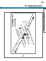
EXPLODED VIEW PRODUCT 64
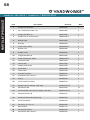
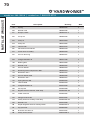
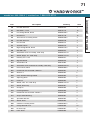
PARTS LIST PRODUCT 68
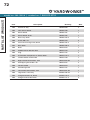
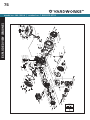
EXPLODED VIEW ENGINE 74
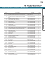
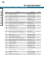
PARTS LIST ENGINE 75
TROUBLESHOOTING 79
WARRANTY 86
TABLE OF CONTENTS

model no. 060-1300-6 | contact us: 1.866.523.5218 model no. 060-1300-6 | contact us: 1.866.523.5218
3
SAFETY INSTRUCTIONS
SAFETY DEFINITIONS
The purpose of safety symbols is to attract
your attention to possible dangers. The
safety symbols, and their explanations,
deserve your careful attention and
understanding. The safety warnings do not
by themselves eliminate any danger. The
instructions or warnings they give are not
substitutes for proper accident prevention
measures.
DANGER
DANGER indicates a hazardous situation
which, if not avoided, will result in death or
serious injury.
WARNING
WARNING indicates a hazardous situation
which, if not avoided, could result in death or
serious injury.
CAUTION
CAUTION indicates a hazardous situation
which, if not avoided, could result in minor or
moderate injury.
NOTICE
NOTICE indicates information considered
important, but not hazard-related (e.g.,
messages relating to property damage).
IMPORTANT SAFETY INSTRUCTIONS
– Carefully read this Operator’s Manual
and any other literature you may
receive. Be thoroughly familiar with
the controls and the proper use of the
tiller and its engine. Know how to stop
the unit and disengage the controls
quickly.
– Never allow children under age 16 to
operate the tiller. Never allow adults
to operate the tiller without proper
instruction.
– Keep the area of operation clear of all
persons, particularly children and pets.
– Keep in mind that the operator or user
is responsible for accidents or hazards
occurring to other people, their
property, and themselves.
– Thoroughly inspect the area where
the tiller is to be used and remove all
foreign objects.
– Be sure all tiller controls are released
and both wheels are in the Wheel
Drive position before starting the
engine.
– Do not operate the tiller without
wearing adequate outer garments.
Avoid loose garments or jewellery that
could get caught in moving parts.
– Do not operate the tiller when barefoot
or wearing sandals, sneakers, or light
footwear. Wear protective footwear
that will improve footing on slippery
surfaces.
– Do not till near underground electric
cables, telephone lines, pipes or
hoses. If in doubt, contact your
telephone or utility company.
Take the following precautions:
– Store fuel in containers specifically
designed for this purpose.
– The gas cap shall never be removed or
fuel added while the engine is running.
Allow the engine to cool for several
minutes before adding fuel.
SAFETY INSTRUCTIONS

model no. 060-1300-6 | contact us: 1.866.523.5218
4
SAFETY INSTRUCTIONS
– Keep matches, cigarettes, cigars,
pipes, open flames and sparks away
from the fuel tank and fuel container.
– Fill fuel tank outdoors with extreme
care. Never fill fuel tank indoors. Use a
funnel or spout to prevent spillage.
– Replace all fuel tank and container
caps securely.
– If fuel is spilled, do not attempt to start
the engine, but move the machine
away from the area of spillage and
avoid creating any source of ignition
until fuel vapours have dissipated.
– Never make adjustments when engine
is running (unless recommended by
manufacturer).
OPERATION
– Do not put hands or feet near or under
rotating parts.
– DO NOT till in reverse.
– Exercise extreme caution when on or
crossing gravel drives, walks, or roads.
Stay alert for hidden hazards or traffic.
Do not carry passengers.
– After striking a foreign object, stop the
engine, remove the wire from the spark
plug and prevent it from touching the
spark plug. Thoroughly inspect the
machine for any damage and repair
the damage before restarting and
operating the machine
– Exercise caution to avoid slipping or
falling.
– If the unit should start to vibrate
abnormally, stop the engine,
disconnect the spark plug wire and
prevent it from touching the spark plug,
and check immediately for the cause.
Vibration is generally a warning of
trouble.
– Stop the engine, disconnect the spark
plug wire and prevent it from touching
the spark plug, whenever you leave the
operating position, before unclogging
the tines, or when making any repairs,
adjustments or inspections.
– Take all possible precautions when
leaving the machine unattended. Stop
the engine. Disconnect the spark plug
wire and move it away from the spark
plug. Be sure that both wheels are in
the Wheel Drive position.
– Before cleaning, repairing, or
inspecting, stop the engine and make
certain all moving parts have stopped.
Disconnect the spark plug wire and
prevent it from touching the spark plug
to prevent accidental starting.
– The flap on the tine hood must be
down when operating the tiller.
– Never use the tiller unless proper
guards, plates, or other safety
protective devices are in place.
– Do not run the engine in an enclosed
area. Engine exhaust contains carbon
monoxide gas, a deadly poison that is
odourless, colourless, and tasteless.
– Keep children and pets away.
– Never operate the tiller under engine
power if the wheels are in the
Freewheel position. In the Freewheel
position, the wheels will not hold the
tiller back and the revolving tines

model no. 060-1300-6 | contact us: 1.866.523.5218 model no. 060-1300-6 | contact us: 1.866.523.5218
5
SAFETY INSTRUCTIONS
could propel the tiller rapidly, possibly
causing loss of control. Always
engage the wheels with the wheel
drive pins in the Wheel Drive position
before starting the engine or engaging
the tines⁄wheels with the forward or
reverse controls.
– Be aware that the tiller may
unexpectedly bounce upward or
jump forward if the tines should strike
extremely hard packed soil, frozen
ground, or buried obstacles like large
stones, roots, or stumps. If in doubt
about the tilling conditions, always use
the following operating precautions to
assist you in maintaining control of the
tiller:
– Use shallower depth regulator settings,
working gradually deeper with each
pass.
– Use slower engine speeds.
– Clear the tilling area of all large
stones, roots or other debris.
– Avoid using downward pressure on
the handlebars. If need be, use slight
upward pressure to keep the tines from
digging too deeply.
– In an emergency, stop the tines and
wheels by releasing whichever lever
is engaged. Do not attempt to restrain
the tiller.
– Do not overload the tiller’s capacity by
attempting to till too deeply at too fast
a rate.
– Never operate the tiller at high
transport speeds on hard or slippery
surfaces. Look behind and use care
when backing up.
– Do not operate the tiller on a slope that
is too steep for safety (greater than 15
degrees). When on slopes, slow down
and make sure you have good footing.
Never permit the tiller to freewheel
down slopes.
– Never allow bystanders near the unit.
– Never operate the tiller without good
visibility or light.
– Never operate the tiller if you are tired;
or under the influence of alcohol, drugs
or medication.
– Operators shall not tamper with the
engine-governor settings on the
machine; the governor controls the
maximum safe operating speed to
protect the engine and all moving parts
from damage caused by overspeed.
Authorized service shall be sought if a
problem exists.
– Do not touch engine parts which may
be hot from operation. Let parts cool
down sufficiently.
– Please remember: You can always
stop the tines and wheels by releasing
control levers (whichever control is
engaged).
– Never pull the tiller towards you.
– Start the engine carefully according
to instructions and with feet well away
from the tines.
– Never pick up or carry a machine while
the engine is running.

model no. 060-1300-6 | contact us: 1.866.523.5218
6
SAFETY INSTRUCTIONS
MAINTENANCE AND STORAGE
– Check all nuts, bolts, and screws
for proper tightness to be sure the
equipment is in safe working condition.
– Never store the tiller with fuel in the
fuel tank inside a building where
ignition sources are present, such as
hot water and space heaters, furnaces,
clothes dryers, stoves, electric motors,
etc. Allow the engine to cool before
storing the unit in any enclosure.
– To reduce the chances of a fire, keep
the engine free of grass, leaves,
or excessive grease.
– Store gasoline in a cool, well-ventilated
area, safely away from any spark- or
flame-producing equipment. Store
gasoline in an approved container,
safely away from the reach of children.
– Never perform maintenance while
the engine is running or the spark
plug wire is connected, except when
specifically instructed to do so.
– If the fuel tank has to be drained, do
this outdoors.
FUEL SAFETY
– Gasoline is highly flammable and
explosive.
– Gasoline can cause a fire or explosion
if ignited.
– Gasoline is a liquid fuel but it’s vapours
can ignite.
– Gasoline is a skin irritant and needs to
be cleaned up immediately if spilled on
skin or clothes.
– Gasoline has a distinctive odour, that
can help detect potential leaks quickly.
– In any petroleum gas fire, flames
should not be extinguished unless by
doing so the fuel supply valve can be
turned OFF. This is because if a fire is
extinguished and a supply of fuel is not
turned OFF, then an explosion hazard
could be created.
– Gasoline expands or contracts with
ambient temperatures. Never fill the
gasoline tank to full capacity, as
gasoline needs room to expand if
temperatures rise.

model no. 060-1300-6 | contact us: 1.866.523.5218 model no. 060-1300-6 | contact us: 1.866.523.5218
7
SAFETY INSTRUCTIONS
When adding or removing gasoline:
– Turn the tiller off and let it cool for at
least two minutes before removing the
gasoline cap. Loosen the cap slowly to
relieve pressure in the tank.
– DO NOT light or smoke cigarettes
when handling gasoline.
– Only fill or drain gasoline outdoors in a
well-ventilated area.
– DO NOT pump gasoline directly into
the tiller at the gas station. Use an
approved fuel container to transfer the
fuel to the tiller.
– DO NOT overfill the gasoline tank.
– ALWAYS keep gasoline away from
sparks, open flames, pilot lights, heat
and other sources of ignition.
When starting the tiller:
– DO NOT attempt to start a damaged
tiller.
– Make certain that the gasoline cap, air
filter, spark plug, fuel lines and exhaust
system are properly in place.
DANGER: GASOLINE AND GASOLINE VAPOURS ARE HIGHLY
FLAMMABLE AND EXPLOSIVE.
Fire or explosion can cause severe burns or death.
– Allow spilled gasoline to evaporate
fully before attempting to start the
engine.
– Make certain that the tiller is resting
firmly on level ground.
When operating the tiller:
– DO NOT tip the tiller or allow fuel or oil
to spill.
When transporting or servicing the
tiller:
– Make certain that the fuel valve is in
the OFF position, and the gasoline
tank is empty.
– Disconnect the spark plug wire.
When storing the tiller:
– Store away from sparks, open flames,
pilot lights, heat and other sources of
ignition.
– Do not store tiller or gasoline near
furnaces, water heaters, or any other
appliances that produce heat or have
automatic ignitions.
WARNING: Handle fuel with care; it is highly flammable and its
vapours are explosive

model no. 060-1300-6 | contact us: 1.866.523.5218model no. 060-1300-6 | contact us: 1.866.523.5218
8
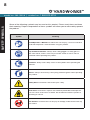
SAFETY SYMBOLS
Symbol Meaning
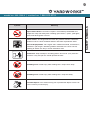
Read Operator’s Manual. To reduce the risk of injury, user must read and
understand operator’s manual before using this product.
Eye and Ear Protection. Always wear safety goggles or safety glasses
with side shields, and as necessary a full face-shield as well as full ear
protection when operating this product.
Footwear. Always wear safety shoes or heavy boots when operating the
machine.
Gloves. Always wear nonslip, heavy-duty protective gloves when operating
this product.
Safety Alert. Precautions that involve your safety.
Risk of Fire. Fuel and its vapours are extremely flammable and explosive.
Fire can cause severe burns or death. Do not add fuel while the product is
operating or still hot.
Hot Surface. To reduce the risk of injury or damage, avoid contact with any
hot surface.
Some of the following symbols may be used on this product. Please study them and learn
their meaning. Proper interpretation of these symbols will allow you to more safely operate
the product.
SAFETY SYMBOLS

model no. 060-1300-6 | contact us: 1.866.523.5218 model no. 060-1300-6 | contact us: 1.866.523.5218
9
SAFETY SYMBOLS
model no. 060-1300-6 | contact us: 1.866.523.5218
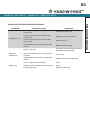
Symbol Meaning
Open Flame Alert. Fuel and its vapours are extremely flammable and
explosive. Keep fuel away from smoking, open flames, sparks, pilot lights,
heat, and other ignition sources.
Toxic Fumes. The engine exhaust from this product contains chemicals
known to cause cancer and birth defects and other reproductive harm.
Risk of Asphyxiation. This engine emits carbon monoxide, an odourless,
colourless poison gas. Breathing carbon monoxide can cause nausea,
fainting or death. Use only in a well-ventilated area.
Clearance. Keep all objects including others at least 10’ (3 m) from this
machine. Only one person should operate the tiller.
Rotating Tines. Avoid injury from rotating tines. Keep hands away.
Rotating Tines. Avoid injury from rotating tines. Keep feet away.
Thrown Objects. This machine may pick up and throw objects which can
cause serious personal injury.

model no. 060-1300-6 | contact us: 1.866.523.5218model no. 060-1300-6 | contact us: 1.866.523.5218
10
OPERATION SYMBOLS
Symbol Meaning
10W-30
Check Oil Level. Recommended oil is 10W-30. The engine can be
seriously damaged without oil. Always check the oil level before using. The
machine must be resting firmly on level ground when checking.
Check Fuel Level. Use clean, fresh, regular unleaded gasoline with a
minimum octane rating of 85 and an ethanol content of less than 10% by
volume.
Choke. Move choke lever to “CHOKE” position.
Throttle: Full Speed. Move the throttle lever to full speed to start the
engine.
Fuel Valve ON. Move the fuel valve lever to “ON” position.
Recoil Starter. Pull recoil starter to start the engine.
Choke RUN. Move choke lever to “RUN” position.
Some of the following symbols may be used on this product. Please study them and learn
their meaning. Proper interpretation of these symbols will allow you to more safely operate
the product.
OPERATION SYMBOLS

model no. 060-1300-6 | contact us: 1.866.523.5218 model no. 060-1300-6 | contact us: 1.866.523.5218
11
OPERATION SYMBOLS
model no. 060-1300-6 | contact us: 1.866.523.5218
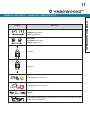
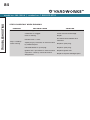
Symbol Meaning
Choke Lever
CHOKE: left position
RUN: right position
Fuel Valve
CLOSED: left position
OPEN: right position
Forward.
Reverse.
Engage Wheels and Tines.
Disengage Wheels and Tines.
Speed.
Transmission Gear Oil. API rated GL-4 or GL-5 Viscosity of SAE 140, SAE
85W-140 or SAE 80W-90.

model no. 060-1300-6 | contact us: 1.866.523.5218model no. 060-1300-6 | contact us: 1.866.523.5218
12
SAFETY LABELS
Label Description
A
1966-L-SF-A
DO NOT TOUCH!
Hot surface.
WARNING
¡NO TOCAR!
Superficie caliente.
ADVERTENCIA
AVERTISSEMENT
NE TOUCHEZ PAS!
Surface chaude.
K 485 152 --- ---
ColorsLPN 1966-L-SF
Rev A
Size 59 x 47 mm
Artwork Notes
3mm corner radius; 2mm safe margin;
whit e to be
prin ted shown i n 50% proce ss magent a
Revision Changes
---
This ar twork belong s to Champion Power Equipment. The contents are confidential and privileged and sha ll not be disclose d to or used by or for
outsid e parties without the explicit c onsent of Champi on Power Equipmen t.
Hot Surface
B
UNLEADED FUEL ONLY. Minimum octane ratingof 85. Maximum 10% ethanol.
GASOLINA REGULAR SOLAMENTE. 85 octanos como mínimo. Máximo de etanol de 10%.
ESSENCE SANS PLOMB SEULEMENT. Indice d’octane minimal de 85. Maximum 10 % d'éthanol.
1967-L-OP-A
K 109 --- --- ---
ColorsLPN 19 67- L-OP
Rev A
Size 130 x 12
Artwork Notes
3mm corner radius; 2mm safe margin;
white to be
printed shown in 50% process magenta
Revision Changes
---
This ar twork belongs to Champion Power Equipment. The contents are con fidential and privileged and shall not be disclosed to or used by or for
outside parties without the explicit consent of Champion Power Equipment.
Fuel
C
1253-L-SF-A
DANGER PELIGRO DANGER
K 485 2945 109 ---
ColorsLPN 12 53-L-S F
Rev A
Size 85 x 35 m m
Artwork Notes
3mm corner radius; 2mm safe margin;
white t o be
print ed shown in 50% pr ocess magen ta
Revision Changes
---
This art work belongs to Champ ion Power Equipment. T he contents are con fidential and privil eged and shall not be discl osed to or used by or for
outside pa rties without t he explicit consen t of Champion Power Eq uipment.
Safety Icons
D
1254-L-SF-A
DANGER PELIGRO DANGER
DO NOT till in reverse.
NO cultivar
en reversa.
NE PAS labourer en
marche arrière.
K 485 --- --- ---
ColorsLPN 1254-L-S F
Rev A
Size 50 x 72 mm
Artwork Notes
3mm corner radius; 2mm safe margin;
white to b e
printe d shown in 50% pr ocess magent a
Revision Changes
---
This artw ork belongs to Champi on Power Equipment. Th e contents are confi dential and privileg ed and shall not be disclo sed to or used by or for
outside par ties without th e explicit consent o f Champion Power Equi pment.
Safety Icons
E
1932-L-SF-A
DANGER PELIGRO DANGER
DO NOT till
in reverse.
NO cultivar
en reversa.
NE PAS labourer en
marche arrière.
K 485 --- --- ---
ColorsLPN 1932-L-SF
Rev A
Size 152.4 x 19.05 mm
Artwork Notes
3mm corner radius; 2mm safe margin;
to be printed
on
white
substrate.
Revision Changes
---
This ar twork belongs t o Champion Power E quipment. The con tents are confi dential and priv ileged and shall not b e disclosed to or us ed by or for
outsid e parties with out the explicit co nsent of Champio n Power Equipment.
Danger
These labels warn you of potential hazards that can cause serious injury. Read them
carefully.
If a label comes off or becomes hard to read, contact Technical Support Team for possible
replacement.
A
B
C
D
E
D
SAFETY LABELS

model no. 060-1300-6 | contact us: 1.866.523.5218 model no. 060-1300-6 | contact us: 1.866.523.5218
13
SAFETY LABELS
model no. 060-1300-6 | contact us: 1.866.523.5218
F
G
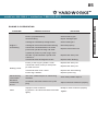
Label Description
F
WARNING
Operati on of this equipme nt may create spar ks that can sta rt fires around
dry veget ation. A spark a rrestor may be re quired. The oper ator should
contact local fire agencies for laws or regulations relating to fire prevention requirements.
ADVERTENCIA
Operación de este equipo puede crear chispas que pueden
iniciar in cendios en vegeta ción seca. Un par achispas puede s er
requeri do. El operador deb ería contact ar las agencias loc ales de incendios p ara leyes o
regulaciones relacionadas con requisitos de prevención de incendios.
AVERTISSEMENT
Le fonct ionnement de cet é quipement peu t créer des
étincelles qui peuvent déclencher des incendies autour de la
végétat ion sèche. Un par e-étincelle s peut être néce ssaire. L'utilisateu r doit communiqu er avec
le servi ce d'incendie loc al pour les lois et le s règlements r elatifs à la préve ntion des incen dies.
1047-L-SF-B
K 152 --- --- ---
ColorsLPN 1047-L- SF
Rev B
Size 89 x 41 mm
Artwork Notes
3mm corner radius; 2mm safe margin
Revision Changes
B: updat ed French per CT C 100493 revi ew
This artw ork belongs to Champi on Power Equipment. Th e contents are confi dential and privileg ed and shall not be disclo sed to or used by or for
outside par ties without th e explicit consent o f Champion Power Equi pment.
Combustion
G
1253-L-SF-A
DANGER PELIGRO DANGER
K 485 2945 109 ---
ColorsLPN 1253-L-S F
Rev A
Size 8 5 x 35 mm
Artwork Notes
3mm corner radius; 2mm safe margin;
white t o be
print ed shown in 50% p rocess mag enta
Revision Changes
---
This art work belongs to Cha mpion Power Equipmen t. The contents ar e confidential and pr ivileged and shall not b e disclosed to or used b y or for
outside p arties withou t the explicit conse nt of Champion Power E quipment.
Safety Icons

model no. 060-1300-6 | contact us: 1.866.523.5218
14
SPECIFICATIONS
Model 100529
Tine Diameter 13⁄" (350 mm)
Tilling Width 19" (480 mm)
Tilling Depth 8" (203 mm)
Tilling Depth Adjustments 1
5
⁄8" (41 mm) increments
Wheel Diameter 13" (330 mm)
Transmission Gear Oil
API rated GL-4 or GL-5;
Viscosity of SAE 140, SAE 85W-140 or SAE 80W-90
Net Weight 160 lb 15 oz (73 kg)
Length 58.7" (149 cm)
Width 19.7" (50 cm)
Height 49.6" (126 cm)
Displacement 212 cc
Type 4-Stroke OHV
Fuel Capacity 0.82 gal (3.1 L)
Oil Capacity 16.9 fl. oz. (500 ml)
Oil Type 10W-30
TILLER SPECIFICATIONS
ENGINE SPECIFICATIONS
FUEL SPECIFICATIONS
Use regular unleaded gasoline with a minimum
octane rating of 85 and an ethanol content of
less than 10% by volume. DO NOT USE E15 or
E85. DO NOT OVERFILL.
NOTICE: Weather will affect engine oil and engine performance.
Change the type of engine oil used based on weather conditions to suit
the engine needs.
This machine meets voluntary safety standard B71.8 – 1996, which is sponsored by
the Outdoor Power Equipment Institute, Inc., and is published by the American National
Standards Institute.
SPECIFICATIONS

model no. 060-1300-6 | contact us: 1.866.523.5218 model no. 060-1300-6 | contact us: 1.866.523.5218
15
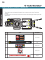
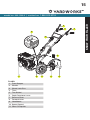
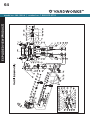
KNOW YOUR TILLER
1
11
2 3 4 5
6
7
8
9
10
1. Front Bumper
2. Wheels
3. Wheel Lock Pins
4. Tines
5. Tine Shield
6. Depth Regulator Lever
7. Reverse Lever
8. Forward Lever
9. Handlebars
10. Speed Control
11. Gear Oil Dipstick
TILLER
KNOW YOUR TILLER

model no. 060-1300-6 | contact us: 1.866.523.5218
16
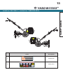
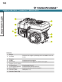
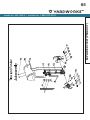
KNOW YOUR TILLER
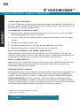
1. Muffler
2. Air Filter
Protects the engine by filtering dust and debris from the
intake.
3. Throttle
4. Choke Used to start the engine.
5. Fuel Valve Used to turn fuel supply on and off to engine.
6. Engine On/Off Switch
7. Oil Drain Bolt Used to drain the oil.
8. Oil Fill Cap/ Dipstick Used to check and fill oil level.
9. Recoil Starter Used to manually start the engine.
10. Gasoline Tank 0.82 gal (3.1 L)
11. Gasoline Tank Cap
ENGINE
1
2
3
4
5
6
7
8
9
10
11

model no. 060-1300-6 | contact us: 1.866.523.5218 model no. 060-1300-6 | contact us: 1.866.523.5218
17
KNOW YOUR TILLER
Engine Oil [16.9 fl. oz. (500 ml)] 1
Oil Funnel 1
8-10 Wrench 1
12-14 Wrench 1
13-16 Wrench 1
Spark Plug Wrench (engine) 1
Needle Nose Pliers (for cotter pins) 1
PARTS INCLUDED
Accessories:
TOOLS INCLUDED TOOLS NOT INCLUDED

model no. 060-1300-6 | contact us: 1.866.523.5218model no. 060-1300-6 | contact us: 1.866.523.5218
18
ASSEMBLY
Your tiller requires some assembly. This unit ships from our factory without oil. It must be
properly serviced with fuel and oil before operation.
If you have any questions regarding the assembly of your tiller, call our
Technical Support Team at 1.866.523.5218. Please have your serial number and model
number available.
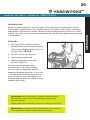
UNPACKING
1. Remove all parts and packaging components.
2. Remove top lid and remove sides.
3. Remove any remaining packaging.
4. With helper, remove the tiller from the shipping crate.
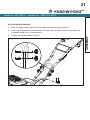
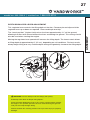
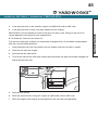
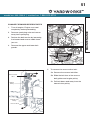
ATTACH LOWER HANDLE
1. Loosen the lower handle bolts.
2. Align the lower handle holes to the middle height adjustment holes in the transmission
cover and install the (4) M10×25 mm flange head bolts and (4) M10 nuts. Tighten all
hardware.
ASSEMBLY

model no. 060-1300-6 | contact us: 1.866.523.5218 model no. 060-1300-6 | contact us: 1.866.523.5218
19
ASSEMBLY
model no. 060-1300-6 | contact us: 1.866.523.5218
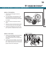
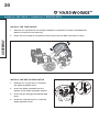
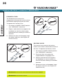
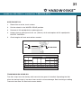
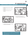
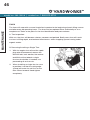
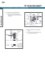
INSTALL THE WHEELS
1. Remove the locking pins from the
wheel hubs.
2. The tiller wheels are directional. For
best performance install the wheels
with the tire thread facing the direction
as shown.
3. Slide the wheel hub onto the wheel
axle.
4. Align the wheel hub hole with the hole
in the axle and insert the locking pin.
5. Rotate the locking pin ring to lock the
pin in position. Repeat on other wheel.
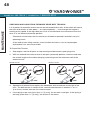
INSTALL THE TINES
1. Check the orientation of the tine blade.
The sharp cutting edge should be
facing the direction of tine rotation for
your tiller.
2. Install the tine assemblies on each tine
axle. Secure with (2) pins and (2) cotter
pins. Bend cotter pins once inserted to
prevent them from coming out.
Before Assembly

model no. 060-1300-6 | contact us: 1.866.523.5218
20
ASSEMBLY
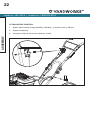
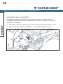
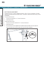
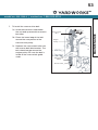
INSTALL THE DEPTH REGULATOR
1. Remove the (1) pin and (1) clip from
the depth regulator lever.
2. Insert the depth regulator into the
bottom of the depth regulator bracket.
3. Insert the pin through the bracket and
lever.
4. Install the clip removed in 1 onto the
depth regulator lever.
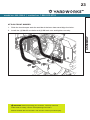
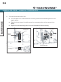
INSTALL THE TINE SHIELD
1. Remove the (4) M10×25 mm flange head bolts installed in the tine shield brackets
above the transmission housing.
2. Place the tine shield on the bracket and secure with the bolts removed in step 1.
Page is loading ...
Page is loading ...
Page is loading ...
Page is loading ...
Page is loading ...
Page is loading ...
Page is loading ...
Page is loading ...
Page is loading ...
Page is loading ...
Page is loading ...
Page is loading ...
Page is loading ...
Page is loading ...
Page is loading ...
Page is loading ...
Page is loading ...
Page is loading ...
Page is loading ...
Page is loading ...
Page is loading ...
Page is loading ...
Page is loading ...
Page is loading ...
Page is loading ...
Page is loading ...
Page is loading ...
Page is loading ...
Page is loading ...
Page is loading ...
Page is loading ...
Page is loading ...
Page is loading ...
Page is loading ...
Page is loading ...
Page is loading ...
Page is loading ...
Page is loading ...
Page is loading ...
Page is loading ...
Page is loading ...
Page is loading ...
Page is loading ...
Page is loading ...
Page is loading ...
Page is loading ...
Page is loading ...
Page is loading ...
Page is loading ...
Page is loading ...
Page is loading ...
Page is loading ...
Page is loading ...
Page is loading ...
Page is loading ...
Page is loading ...
Page is loading ...
Page is loading ...
Page is loading ...
Page is loading ...
Page is loading ...
Page is loading ...
Page is loading ...
Page is loading ...
Page is loading ...
Page is loading ...
-
 1
1
-
 2
2
-
 3
3
-
 4
4
-
 5
5
-
 6
6
-
 7
7
-
 8
8
-
 9
9
-
 10
10
-
 11
11
-
 12
12
-
 13
13
-
 14
14
-
 15
15
-
 16
16
-
 17
17
-
 18
18
-
 19
19
-
 20
20
-
 21
21
-
 22
22
-
 23
23
-
 24
24
-
 25
25
-
 26
26
-
 27
27
-
 28
28
-
 29
29
-
 30
30
-
 31
31
-
 32
32
-
 33
33
-
 34
34
-
 35
35
-
 36
36
-
 37
37
-
 38
38
-
 39
39
-
 40
40
-
 41
41
-
 42
42
-
 43
43
-
 44
44
-
 45
45
-
 46
46
-
 47
47
-
 48
48
-
 49
49
-
 50
50
-
 51
51
-
 52
52
-
 53
53
-
 54
54
-
 55
55
-
 56
56
-
 57
57
-
 58
58
-
 59
59
-
 60
60
-
 61
61
-
 62
62
-
 63
63
-
 64
64
-
 65
65
-
 66
66
-
 67
67
-
 68
68
-
 69
69
-
 70
70
-
 71
71
-
 72
72
-
 73
73
-
 74
74
-
 75
75
-
 76
76
-
 77
77
-
 78
78
-
 79
79
-
 80
80
-
 81
81
-
 82
82
-
 83
83
-
 84
84
-
 85
85
-
 86
86


Yardworks 060-1300-6 User manual
- Category
- Mini tillers
- Type
- User manual
- This manual is also suitable for
Ask a question and I''ll find the answer in the document
Finding information in a document is now easier with AI
Related papers
-
 Yardworks 060-3890-8 User manual
-
 Yardworks 055-0361-0 User manual
-
 Champion Power Equipment 100666 Owner's manual
-
 Yardworks 060-3014-6 User manual
-
 Yardworks 48V Battery-Powered Cordless Snow Shovel Owner's manual
-
 Yardworks 060-2288-0 User manual
-
 Yardworks GLR120CU Owner's manual
-
 Yardworks 96V Self Propelled Lawn Mower Owner's manual
-
 Yardworks 060-1721-4 User manual
-
 Yardworks 060-3895-8 Owner's manual


Other documents
-
 Champion Power Equipment 100379 User manual
-
Champion LARH0950 User manual
-
 Excell R430 Owner's manual
-
 Rato RG3.6-100Q-Z-II Owner's manual
-
Honda F210 Owner's manual
-
Platinum LATR4000 User manual
-
Southland SRTT196E User guide
-
-
 LONCIN LC154f-1 Owner's manual
-
Champion Power Equipment 100862 Owner's manual


