TRANSPORT PC
PRO MAGNETIC ELLIPTICAL
TRAINER
ITEM NO.: 93690
OWNER’S MANUAL
IMPORTANT: Read all instructions carefully before using this product. Retain this
owner’s manual for future reference.
The specifications of this product may vary from this photo, subject to change without notice.
2015, Nov.

1
TABLE OF CONTENTS
WARRANTY ------------------------------------------------------------------------------- 2
IMPORTANT SAFETY INSTRUCTIONS ------------------------------------------- 3
PARTS LIST ------------------------------------------------------------------------------- 4
HARDWARE PACKING LIST --------------------------------------------------------- 6
TOOLS -------------------------------------------------------------------------------------- 6
OVERVIEW DRAWING ----------------------------------------------------------------- 7
ASSEMBLY INSTRUCTIONS --------------------------------------------------------- 8
OPERATING THE COMPUTER ------------------------------------------------------ 16
ADJUSTMENT ---------------------------------------------------------------------------- 22
MAINTENANCE -------------------------------------------------------------------------- 23
TROUBLESHOOTING ------------------------------------------------------------------ 23
WARM UP AND COOL DOWN ROUTINE ----------------------------------------- 24

2
ONE YEAR LIMITED WARRANTY
LifeGear Inc. warrants to the original purchaser that this product is free from defects in
material and workmanship when used for the purpose intended, under the conditions that it
has been installed and operated in accordance with LifeGear's Owner's Manual. LifeGear's
obligation under this warranty is limited to replacing or repairing free of charge, any parts
which may prove to be defective under normal home use. This warranty does not include
any damage caused by improper operation, misuse or commercial application.
From the date of purchase, the frame is warranted to be free from defects for 1 (one) year.
This warranty is offered only to the original owner and is not transferable. Proof of
purchase is required.
When ordering replacement parts please have the following information ready:
1. Owner's Manual
2. Model Number
3. Description of Parts
4. Part Number
5. Date of Purchase

3
IMPORTANT SAFETY INSTRUCTIONS
Basic precautions should always be followed, including the following important
safety instructions when using this equipment. Read all instructions before using
this equipment.
1. Read all instructions and follow it carefully before using this equipment. Make sure the
equipment is properly assembled and tightened before use.
2. Before exercise, in order to avoid injuring the muscle, warm-up exercises are
recommended.
3. Please make sure all parts are not damaged and fixed well before use. This
equipment should be placed on a flat surface when using. Using a mat or other
covering material on the ground is recommended.
4. Please wear proper clothes and shoes when using this equipment; do not wear clothes
that may catch any part of the equipment.
5. Do not attempt any maintenance or adjustments other than those described in this
manual. Should any problems arise, discontinue use and consult your local dealer.
6. Be careful when step on or leave the pedal always hold the handlebars first. Make the
pedal at your side at the lowest position, step on the pedal, and stride over the main
frame then step on the other pedal. When using, please hold the handlebar by hands,
make the pedals running smoothly by push or pull handlebars, then run the equipment
regularly by cooperation of hands and feet. After exercise, please also make one
pedal at the lowest position and leave your foot on the higher pedal first and then
another.
7. Do not use the equipment outdoors.
8. This equipment is for household use only. It is not a commercial model.
9. Only one person at a time should use this equipment.
10. If you feel any chest pains, nausea, dizziness, or short of breath, you should stop
exercising immediately and consult your physician before continuing.
11. Care should be taken in mounting or dismounting the equipment.
12. Do not allow children to use or play on the equipment. Keep children and pets away
from the equipment while in use. This machine is designed for adults use only. The
minimum free space required for safe operation is not less than two meters.
13. The maximum weight capacity for this product is 110 kgs.
WARNING: Before beginning any exercise program consult your physician.
This is especially important for the people who are over 35 years old or who have
pre-existing health problems. Read all instructions before using any fitness
equipment.
CAUTION: Read all instructions carefully before operating this product.
Retain this Owner’s Manual for future reference.

4
PARTS LIST
No. Description Qty No. Description Qty
001 Handrail End Cap Ø32x1.5t 2 024 Curve Washer Ø16xØ8x1.5t 10
002L Left Handrail Ø32x1.5t 1 025 Bolt M8x15mm 8
002R Right Handrail Ø32x1.5t 1 026 Nut M6 2
003L Left Handrail Arm 1 027 Phillips Self Tapping Screw
ST4.2x20mm
10
003R Right Handrail Arm 1 028 Left Handrail Arm Cover-A 1
004 Handrail Foam Grip
Ø31xØ37x480
2 029 Left Handrail Arm Cover-B 1
005 Top Decorative Cover for Front
Post
1 030 Computer Extension Wire I 1
006 Rear Decorative Cover for Front
Post
1 031 Extension Wire 1
007 Front Decorative Cover for Front
Post
1 032 Front Post 1
008 Screw ST2.9x16mm 20 033 Motor 1
009 Screw ST4.2x20mm 8 034 Right Handrail Arm Cover-A 1
010 Nylon Nut M6 16 035 Right Handrail Arm Cover-B 1
011 Curve Washer Ø6 4 036 Washer Ø10xØ5x1.0t 4
012 Carriage Bolt M6x35mm 4 037 Bolt Ø10x46 2
013 Bolt M8x20mm 4 038 Powder Metal Bushing
Ø14.2xØ10.2x10
4
014 Spring Washer Ø8 4 039 Motor Tension Cable 1
015 Washer Ø38x3 4 040 Big Washer Ø6 9
016 Powder Metal Bushing Ø38x14 8 041 Bolt M6x15mm 6
017 Plastic Bushing Ø32x69 2 042 Spring Washer Ø6 2
018 Computer (XLG-903SPGM) 1 043 Tension Bracket 2
019 Nut M10 2 044 Flywheel Ø260x123 1
020 Adjustable Leveler M10 2 045L Front Left Foot Bar Cover 2
021 Hand Pulse Sensor with Wire
750mm
2 045R Front Right Foot Bar Cover 2
022 Handlebar Foam Grip
Ø33xØ27x750
2 046 Eyebolt M6x36 2
023 Handlebar 1 047 Hexagon Head Bolt M6x40 8

5
PARTS LIST
No. Description Qty No. Description Qty
048L Front Left Stabilizer End Cap 1 071 Screw ST4.2x25mm 8
048R Front Right Stabilizer End Cap 1 072 Sensor Wire I (1600L) 1
049 Front Stabilizer Ø76 1 073 Belt Pulley Shaft 1
050 Bolt M8x90mm 4 074 Plastic Disc Cap 2
051 Transport Wheel Ø45x19 2 075L Left Shroud 1
052 Nut M10x1.0 2 075R Right Shroud 1
053L Left Foot Bar 1 076 Phillips Self Tapping Screw
ST4.2x25mm
8
053R Right Foot Bar 1 077 Screw ST4.2x15mm 16
054 Big Curve Washer Ø8xØ20x1.5t 4 078 Crank 2
055 Rear Stabilizer Ø76 1 079 Crank Cover 2
056 Front Post Cover 1 080 Nut M10x1.25 2
057 Plastic Cover 1 081 Plastic Spacer Ø38xØ19x40 2
058 Spring Clip Ø17 2 082 Nylon Nut M8 2
059 Bearing 6003-2Z 2 083 Washer Ø16xØ8x1.5t 2
060 Main Frame 1 084 Powder Metal Bushing Ø18xØ8x10 4
061 Belt PJ400J6 1 085 Foot Bar Bracket 2
062 Belt Pulley Ø260J6 1 086 Hexagon Head Bolt M8x50 2
063 Bolt M6x10mm 1 087 Foot Bar Bracket Cover 2
064 Bolt M8x10mm 1 088L Left Foot Pedal 1
065 Bearing 6000ZZ 2 088R Right Foot Pedal 1
066 Washer Ø14xØ10x1.0t 2 089 Computer Extension Wire II 2
067 Idle Wheel Bracket 1 090 Power Supply Wire 1
068 Bolt M8x25mm 1 091 Nut M12x3.0t 1
069 Rear Stabilizer End Cap Ø76 2 092 AC Adapter 1
070 Screw ST2.9x12mm 2 093 Bolt M8x20mm 2

6
HARDWARE PACKING LIST
TOOLS
Allen Wrench S6
1 PC
Multi Hex Tool with Phillips Screwdriver
S10, S13, S14, S15
1 PC
(8) Screw ST2.9x16mm
20 PCS
(10) Nylon Nut M6
10 PCS
(9) Screw ST4.2x20mm
4 PCS
(11) Curve Washer Ø6
4 PCS
(12) Carriage Bolt M6x35mm
4 PCS
(40) Big Washer Ø6
6 PCS
(50) Bolt M8x90mm
4 PCS
(47) Hexagon Head Bolt
M6x40
6 PCS
(54) Big Curve Washer
Ø8xØ20x1.5t
4 PCS
(27) Phillips Self Tapping
Screw ST4.2x20mm
10 PCS

7
54
50
20
19
80
79
78
75L
51
10
47
54
50
49
48L
80
26
42
43
52
46
48R
73
10
37
38
82
87
83
13
16
85
39
10
40
87
14
13
85
8
35
3R
22
21
18
4
2R
5
1
2L
4
7
10
11
16
15
29
28
3L
37
38
6
14
13
12
17
16
10
11
12
15
14
13
24
93
22
9
23
27
27
86
83
82
71
78
79
34
27
68
63
40
65
66
64
72
67
70
76
75R
77
41
69
61
58
60
59
58
56
9
41
40
47
27
45R
45L
8
27
53L
40
10
84
86
57
47
77
69
55
76
9
32
27
62
53R
88R
88L
44
74
74
81
81
15
59
71
77
21
21
16
9
8
45R
45L
27
14 15
16
46
51
10
8
41
40
38
16
17
16
27
27
8
27
8
8
8
1
9
21
84
89
89
30
30
31
31
36
76
33
91
90
92
24
25
24
25
OVERVIEW DRAWING

8
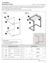
ASSEMBLY INSTRUCTIONS
1. Front and Rear Stabilizers Installation
Position the Front Stabilizer (49) in front of Main Frame (60) and align bolt holes.
Attach the Front Stabilizer (49) onto the front curve of the Main Frame (60) with two
M8x90mm Bolts (50) and two Ø8xØ20x1.5t Big Curve Washers (54). Tighten bolts and
curve washers with an Allen Wrench provided.
Position the Rear Stabilizer (55) behind the Main Frame (60) and align bolt holes.
Attach the Rear Stabilizer (55) onto the rear curve of the Main Frame (60) with two
M8x90mm Bolts (50) and two Ø8xØ20x1.5t Big Curve Washers (54). Tighten bolts and
curve washers with an Allen Wrench provided.
Install two M10 Adjustable Leveler (20) onto the Rear Stabilizer (55).
Hardware:
Allen Wrench S6
Tool:
49
54
50
55
54
50
20
60
(50) Bolt M8x90mm
4 PCS
(54) Big Curve Washer
Ø8xØ20x1.5t
4 PCS

9
2. Front Post and Front Post Cover Installation
Remove eight Ø16xØ8x1.5t Curve Washers (24) and eight M8x15mm Bolts (25) from the
Main Frame (60). Remove bolts and curve washers with an Allen Wrench provided.
Slide the Front Post Cover (56) up to the Front Post (32).
Connect the Extension Wire (31) from the Main Frame (60) to the Computer Extension Wire
I (30) from the Front Post (32).
Insert the Front Post (32) onto the tube of the Main Frame (60) and secure with eight
Ø16xØ8x1.5t Curve Washers (24) and eight M8x15mm Bolts (25) that were removed.
Tighten bolts and curve washers with an Allen Wrench provided.
Slide the Front Post Cover (56) down to the Front Post (32).
Allen Wrench S6
Tool:
30
56
39
32
60
24
25
24
25
24
25

10
3. Left/Right Handrail Arms, Left/Right Foot Bars, and Foot Bar Bracket Covers
Installation
Remove two M8x20mm Bolts (13), two Ø8 Spring Washers (14), and two Ø38x3 Washers
(15) from the left and right horizontal axes of the Front Post (32). Remove bolts and
washers with an Allen Wrench provided. Then attach the Left Handrail Arm (3L) onto the
left horizontal axis of the Front Post (32) with one M8x20mm Bolt (13), one Ø8 Spring
Washer (14), and one Ø38x3 Washer (15) that were removed. Tighten bolt and washers
with an Allen Wrench provided.
Remove two M8x20mm Bolts (13), two Ø8 Spring Washers (14), and two Ø38x3 Washers
(15) from the left and right Cranks (78). Remove bolts and washers with an Allen Wrench
provided. Then attach the left Foot Bar Bracket (85) to the left Crank (78) with one
M8x20mm Bolt (13), one Ø8 Spring Washer (14), and one Ø38x3 Washer (15) that were
removed. Tighten bolt and washers with an Allen Wrench provided.
Attach the Foot Bar Bracket Cover (87) onto the rear end of the Left Foot Bar (53L) and Foot
Bar Bracket (85) with one ST4.2x20mm Phillips Self Tapping Screw (27). Tighten screw
with a Multi Hex Tool with Phillips Screwdriver provided.
Use the same procedure to attach the Right Handrail Arm (3R) onto the right horizontal axis
of the Front Post (32) and right Foot Bar Bracket (85) to the right Crank (78).
Hardware:
Allen Wrench S6
Tool:
Multi Hex Tool with Phillips Screwdriver
S10, S13, S14, S15
87
27
15
14
13
78
3R
3L
32
17
15
14
13
1514
13
81
15
14
13
87
27
53R
53L
78
85
85
(27) Phillips Self Tapping
Screw ST4.2x20mm
2 PCS

11
4. Left/Right Foot Pedals, and Front Left/Right Foot Bar Covers Installation
Attach the Left Foot Pedal (88L) onto the Left Foot Bar (53L) with three M6 Nylon Nuts (10),
three Ø6 Big Washers (40), and three M6x40 Hexagon Head Bolts (47). Tighten bolts and
nylon nuts with a Multi Hex Tool with Phillips Screwdriver provided.
Attach the Front Left/Right Foot Bar Covers (45L, 45R) onto the Left Foot Bar (53L) with
three ST2.9x16mm Screws (8) and two ST4.2x20mm Phillips Self Tapping Screws (27).
Tighten screws with a Multi Hex Tool with Phillips Screwdriver provided.
Use the same procedure to attach the Right Foot Pedal (88R) onto the Right Foot Bar (53R)
and the Front Left/Right Foot Bar Covers (45L, 45R) onto the Right Foot Bar (53R).
Note: Make sure when attaching Left/Right Foot Pedals (88L, 88R) onto Left/Right
Foot Bars (53L, 53R) that Left/Right Foot Pedals (88L, 88R) should be adjusted to the
same bolt holes.
Hardware:
Multi Hex Tool with Phillips Screwdriver
S10, S13, S14, S15
Tool:
45R
45R
45L
45L
8
27
27
88R
88R
88L
88L
47
47
10
10
40
40
47
47
40
40
10
10
27
27
8
8
27
27
27
27
45L
45L
45R
45R
53L
53L
53R
53R
(47) Hexagon Head Bolt
M6x40
6 PCS
(40) Big Washer Ø6
6 PCS
(10) Nylon Nut M6
6 PCS
(27) Phillips Self Tapping
Screw ST4.2x20mm
4 PCS
(8) Screw ST2.9x16mm
6 PCS

12
5. Left/Right Handrails and Left/Right Handrail Arm Covers-A/B Installation
Attach the Left/Right Handrails (2L, 2R) onto the Left/Right Handrail Arms (3L, 3R) with four
M6 Nylon Nuts (10), four Ø6 Curve Washers (11), and four M6x35mm Carriage Bolts (12).
Tighten bolts and nylon nuts with a Multi Hex Tool with Phillips Screwdriver provided.
Attach the Left Handrail Arm Cover-A (28) and Left Handrail Arm Cover-B (29) onto the
Left Handrail Arm (3L) with four ST2.9x16mm Screws (8) and two ST4.2x20mm Phillips Self
Tapping Screws (27). Tighten screws with a Multi Hex Tool with Phillips Screwdriver
provided.
Attach the Right Handrail Arm Cover-A (34) and Right Handrail Arm Cover-B (35) onto the
Right Handrail Arm (3R) with four ST2.9x16mm Screws (8) and two ST4.2x20mm Phillips
Self Tapping Screws (27). Tighten screws with a Multi Hex Tool with Phillips Screwdriver
provided.
Hardware:
Multi Hex Tool with Phillips Screwdriver
S10, S13, S14, S15
Tool:
2R
2L
29
28
35
8
34
27
10
11
12
27
8
27
27
10
11
12
3R
3L
(10) Nylon Nut M6
4 PCS
(11) Curve Washer Ø6
4 PCS
(12) Carriage Bolt M6x35mm
4 PCS
(8) Screw ST2.9x16mm
8 PCS
(27) Phillips Self Tapping
Screw ST4.2x20mm
4 PCS

13
6. Top and Rear/Front Decorative Covers for Front Post Installation
Attach the Top and Rear/Front Decorative Covers for Front Post (5, 6, 7) onto the Front Post
(32) with six ST2.9x16mm Screws (8) and two ST4.2x20mm Screws (9). Tighten screws
with a Multi Hex Tool with Phillips Screwdriver provided.
Hardware:
Multi Hex Tool with Phillips Screwdriver
S10, S13, S14, S15
Tool:
5
7
6
9
8
8
8
32
32
(8) Screw ST2.9x16mm
6 PCS
(9) Screw ST4.2x20mm
2 PCS

14
7.
Handlebar and Computer Installation
Remove two Ø16xØ8x1.5t Curve Washers (24) and two M8x20mm Bolts (93) from the Front
Post (32). Remove bolts and curve washers with an Allen Wrench provided. Connect the
Computer Extension Wire I (30) from the Front Post (32) to the Computer Extension Wire II
(89) from the Handlebar (23). Then attach the Handlebar (23) onto the Front Post (32) with
two Ø16xØ8x1.5t Curve Washers (24) and two M8x20mm Bolts (93) that were removed.
Tighten bolts and curve washers with an Allen Wrench provided.
Connect the Computer Extension Wires II (89) and Hand Pulse Sensor Wires (21) from the
Handlebar (23) to the wires that come from the Computer (18) and then attach the Computer
(18) onto the top end of the Handlebar (23) with two ST4.2x20mm Screws (9). Tighten
screws with a Multi Hex Tool with Phillips Screwdriver provided.
Hardware:
Allen Wrench S6
Tool:
Multi Hex Tool with Phillips Screwdriver
S10, S13, S14, S15
24
24
93
93
23
23
30
30
32
32
18
18
21
21
21
21
9
89
89
89
89
(9) Screw ST4.2x20mm
2 PCS

15
8. AC Adapter Installation
Plug one end of the AC Adapter (92) into the power jack of the Power Supply Wire (90) on
the back of the Left Shroud (75L). Before plugging in, make sure to check carefully the
specifications on the Adapter. Plug the other end of the AC Adapter (92) into the electrical
wall outlet.
90
92
75L

16
OPERATING THE COMPUTER
BUTTON FUNCTIONS:
START/STOP: Press the START/STOP button to start or stop training.
MODE: By holding the MODE button for two seconds the user can reset all values to 0.
Press the MODE button to change the function from PROGRAMS, TIME, DISTANCE, CAL,
TARGET, 10 intervals, GENDER, HEIGHT, WEIGHT, and AGE. The chosen function shall
flash. Please note that not all the functions can be selected in every program according to
the types of each program.
UP: Press the UP button to select or increase the functional values of PROGRAMS, TIME,
DISTANCE, TARGET, 10 intervals, GENDER, HEIGHT, WEIGHT, and AGE.
DOWN: Press the DOWN button to select or decrease the functional values of PROGRAMS,
TIME, DISTANCE, TARGET, 10 intervals, GENDER, HEIGHT, WEIGHT, and AGE.
BODY FAT: Press the BODY FAT button to select the PROGRAM 19.
RECOVERY: The Pulse Recovery is for personal orientation and compares the approximate
pulse rate before and after training. You will notice that your fitness will improve with
regular exercise. The Pulse Recovery feature is to be used directly after your workout. To
use this function:
1) Grip the handlebar sensors with both your hands during exercise.
2) Press the RECOVERY button.
3) The time will countdown from 60 to 0 seconds. Grip the handlebar sensors with both
your hands.
Note: If there is no pulse reading within 4 seconds reposition your hands on the Hand
Pulse Sensors.
4) Your personal fitness Pulse Recovery level will appear on the display. When countdown
is complete, the Pulse Recovery grade will be displayed.
Your ratings for Pulse Recovery are as follows:
F1.0 = Excellent F4.0 = Below Average
F2.0 = Good F5.0 = Not Good
F3.0 = Fair F6.0 = Poor

17
About Display:
STOP: Indicates the program selected has stopped. User is free to change the programs
and the value of functions applied.
PROGRAM: Indicates the programs selected from PROGRAM 0 to PROGRAM 19.
LEVEL: Indicates the level of loading selected from LEVEL 1 to LEVEL 16.
GENDER: Indicates the gender (Male or Female) selected.
TIME/BMR/HEIGHT/WEIGHT/AGE Display: Indicates only one functional value of TIME,
BMR, HEIGHT, WEIGHT, or AGE displayed depending on the programs.
SPEED K(M)/RPM/BMI Display: Indicates only one functional value of SPD, RPM, BMI, or
K(M) displayed depending on the programs.

18
DIST/FAT% Display: Indicates only one functional value of DIST (DISTANCE) or FAT%
displayed depending on the programs.
WATT/CAL Display: Indicates only one functional value of WATT or CAL displayed
depending on the programs.
T.H.R./PULSE Display: Indicates only one functional value of T.H.R (TARGET HEART
RATE) or PULSE displayed depending on the programs.
LOADING Profiles: There are 10 intervals of loading bars, and 8 bars in each interval.
Each intervals represents 3 minutes workout (without the change of TIME value), and each
bar represents 2 levels of loading.

19
Operating Ranges
Values Range (Count up) Count down Preset Increment (Decrement)
PROGRAM 0 ~ 19 19 ~ 0 1 1
LEVEL 1 ~ 16 16 ~ 1 N/A 1
GENDER Male, Female Male, Female Male N/A
TIME 0:00 ~ 99:59 99:00 ~ 5:00 0:00 1:00
HEIGHT (cm) 110.0 ~ 200.0 200.0 ~ 110.0 175.0 0.5
WEIGHT (kg) 10.0 ~ 200.0 200.0 ~ 10.0 70.0 0.2
AGE 10 ~ 99 99 ~ 10 30 1
DISTANCE 0.00 ~ 99.9 99.9 ~ 0.00 0.00 0.1
CALORIES 0.0 ~ 999 999 ~ 0.0 0.0 1.0
TARGET H.R. 60 ~ 200 200 ~ 60 N/A 1
WATT 30.0 ~ 350 350 ~ 30.0 200 1
Things You Should Know Before Exercising
The values calculated or measured by the computer are for exercise purpose only, not for
medical purpose.
Programs Selection:
There are 20 programs including 1 Manual Program, 9 Pre-set Programs, 4 User Setting
Programs, 1 WATT Control Program, 4 Heart Rate Control Programs, and 1 Body Fat
Program.
Program Graph:
Each graph shown is the profile of the loading in each interval. With the value of TIME
counting up, each interval is 3 minutes that all the columns make up 30 minutes. With the
value of TIME counting down, each interval is the value of setup TIME divided by 10. For
example, if the time value is setup to 40 minutes, each interval will be 40 minutes divided by
10 intervals (40/10=4). Then, each interval will be 4 minutes. The following graphs are all
the profiles in the computer.
Page is loading ...
Page is loading ...
Page is loading ...
Page is loading ...
Page is loading ...
Page is loading ...
/