Page is loading ...

Page 1
This appliance may be installed in
an aftermarket, permanently located,
manufactured home (USA only) or mobile
home, where not prohibited by local codes.
This appliance is only for use with the type
of gas indicated on the rating plate.
This appliance is not convertible for use with
other gases, unless a certied kit is used.
WARNING
If not installed, operated and maintained
in accordance with the manufacturer’s
instructions, this product could expose you
to substances in fuel or from fuel combustion
which can cause death or serious illness.
WARNING
FIRE OR EXPLOSION HAZARD
Failure to follow safety warnings exactly could
result in serious injury, death or property
damage.
— Do not store or use gasoline or other
ammable vapors and liquids in the
vicinity of this or any other appliance.
— WHAT TO DO IF YOU SMELL GAS
• Do not try to light any appliance.
• Do not touch any electrical switch;
do not use any phone in your building.
• Leave the building immediately.
• Immediately call your gas supplier
from a neighbor’s phone. Follow
the gas supplier’s instructions.
• If you cannot reach your gas
supplier, call the re department.
— Installation and service must be
performed by a qualied installer,
service agency or the gas supplier.
HOT GLASS
DO NOT TOUCH
NEVER
WILL
CAUSE BURNS.
GLASS
UNTIL COOLED.
ALLOW CHILDREN
TO TOUCH GLASS.
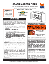
WARNING
A barrier designed to reduce the risk of burns from the
hot viewing glass is provided with this appliance and shall
be installed for the protection of children and other at-risk
individuals.
NOTE: Barrier required, may be sold separately.
INSTALLER:
Leave this manual with the appliance.
CONSUMER:
Retain this manual for future reference.
DIRECT
-
VENT ZERO
CLEARANCE GAS FIREPLACE
HEATER MODEL SERIES:
MULTIFUNCTION
REMOTE (MF)
DVLL36BP92K(N,P)-1
DVLL48BP92K(N,P)-2
UL FILE NO. MH30033
GAS-FIRED
INSTALLATION INSTRUCTIONS
AND OWNER'S MANUAL

41352-0-0120Page 2
BEFORE YOU START
SAMPLE WARNINGS AND DEFINITIONS:
DANGER
Indicates a hazardous situation which, if not avoided, will
result in death or serious injury.
WARNING
Indicates a hazardous situation which, if not avoided, could
result in death or serious injury.
CAUTION
Indicates a hazardous situation which, if not avoided, could
result in minor or moderate injury.
NOTICE: Addresses practices not related to personal injury.
____________________________________________________
1. Read the safety information on pages 61 - 62.
2. If located in the Commonwealth of Massachusetts,
please note the special requirements on page 63.
3. Areyougoingtoinstallablowerintothereplace?
See pages 8 - 10.
4. Whereareyougoingtoinstallthereplace?Seepage13.
5. Frame the opening. See page 20.
6. Install the gas lines. See pages 16 - 17.
7. Install the wiring. See pages 18 - 19.
8. Install the venting. See pages 22 - 41.
9. Installthereplace.Seepages20-23.
10. Install the remote system. See pages 43 - 50.
11. Liner requirements. See page 7.
12. Install the glass media. See page 42.
13. Lightthereplaceandtroubleshoot.Seepages51-53.
14. Showthehomeownerhowtooperatethereplace.
15. Show the homeowner how to do the basic maintenance.
UNPACKING THE FIREPLACE
1. Cut binding straps and shrink wrap.
2. Remove top board and corner posts.
3. Liftreplaceoffofthepallet.
4. Remove non-combustible boards from pallet and set aside.
5. Verifythatthereplaceandcomponentshavenotbeen
damaged during shipping.
6. Setreplaceinalocationneartoitsnalinstallationlocation.
INSTALLATION CONSIDERATIONS - FIREPLACE
INSTALLATION GUIDELINES
When planning a replace installation, it’s necessary to
determine:
• Gas supply piping (right side entrance).
• Electrical supply requirements
(120V, 60Hz, 1 Amp) (right side entrance)
• These models do not include the Accent Light assembly.
However, the Accent Light Kit may be purchased and
installedduringorafterreplaceinstallation.Instructionsare
supplied with the Accent Light Kit.
• Proper opening size of framing required for installation of
thereplace.Theframingofthereplacewilldeterminehow
thereplacenishingmaterialswillbeapplied.Refertothe
installation information on pages 20 to 23.
•
Theblowerkitiseasiertoinstallatthetimeofreplace
installations. See blower installation section on pages 8 to 10.
Inplanningtheinstallationforthereplace,determinewherethe
replaceistobeinstalledandwhetheroptionalaccessoriesare
desired. Gas supply piping should also be planned at this time.
The replace can be mounted on any of these surfaces:
1. Aathardcombustibleornon-combustiblesurface.
2.
A raised platform of combustible or non-combustible material.
Ifthereplaceisinstalleddirectlyoncarpeting,tileorother
combustiblematerialotherthanwoodooring,itshouldbe
installed on a metal or wood panel extending the full width and
depthofthereplace.
Thereplaceisdesignedtobeinstalledinazero-clearance
enclosure. This means that combustible materials must be
locatedatclearancesspeciedorprovidedbystandoffsor
spacersattachedtothereplace.
Combustible materials can come in contact with the nailing
angesprovided.
HOMEOWNER REFERENCE INFORMATION
Recordthefollowinginformationaboutyourreplace.
Model: ____________________________________ Date Purchased/Installed: _________________
Serial Number: _____________________________ Location on Fireplace: ____________________
Dealership: ________________________________ Dealer Phone: _________________________
Notes: ______________________________________________________________________________
____________________________________________________________________________________

41352-0-0120 Page 3
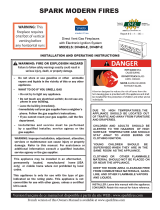
CARTON CONTENTS & HARDWARE PACK
5
6
7
8
9
10
11
12
Items not shown to scale.
INDEX NUMBER DESCRIPTION QUANTITY SUPPLIED
1 DoorRemovalTool(attachedtoreplace) 1
2 Product Registration Card 1
3 AA Battery 4
4 AAA Battery 3
5 Cover Plate, Battery Box 1
6 Remote 1
7 Junction Box Cover 1
8 Duplex Receptacle 1
9 Flue Restrictor Assembly 1
10 Battery Box 1
11 Grommet, 5/8 DIA 1
12 Wire Assembly, Module to Interface 2
A #10 x 1/2 Screw 22
B #8 x 1 Self-Drilling Screw* 15
C Nailing Flange 4
* For use in mounting non-combustible board to standoffs.
See Parts Lists on pages 50 for ordering replacement parts. Do not order batteries, bolts, screws, washers or nuts. They are standard
hardware items and can be purchased at any local hardware store.
1” PHILLIPS SELF DRILLING SCREW
#10 X ½” HEX HEAD SCREW
NAILING FLANGES
B
A
C

41352-0-0120Page 4
TABLE OF CONTENTS
Introduction ....................................................................................................................................5
Specications.................................................................................................................................6
Accessories ...................................................................................................................................7
FBB20 Blower Installation...................................................................................................... 8 - 10
Fireplace Dimensions ..................................................................................................................11
Clearances...................................................................................................................................12
Locating Fireplace .......................................................................................................................13
Vent Termination Clearances ............................................................................................... 14 - 15
Gas Supply .......................................................................................................................... 16 - 17
Electrical Connections ......................................................................................................... 18 - 19
Installation............................................................................................................................ 20 - 23
VentSystemIdentication ...........................................................................................................24
Vent Systems ...............................................................................................................................24
Venting Fireplace - Top ........................................................................................................ 25 - 27
Top Vent - Horizontal Termination ................................................................................................28
Top Vent - Vertical Termination ....................................................................................................29
Vertical Termination ............................................................................................................. 30 - 31
DVVK-4F Flex Vent Instructions ..................................................................................................32
DVVK-4FV Direct Vent Termination Kit ................................................................................ 33 - 39
Framing And Finishing ......................................................................................................... 40 - 41
Glass Placement..........................................................................................................................42
Multifunction Remote Operating Instructions ....................................................................... 43 - 50
Intermittent Pilot Lighting Instructions ..........................................................................................51
Control System Troubleshooting.......................................................................................... 52 - 53
Parts View ....................................................................................................................................54
Parts List ......................................................................................................................................55
Component Wiring Diagram ........................................................................................................56
Maintenance And Service .................................................................................................... 57 - 61
Important Safety Information ............................................................................................... 62 - 63
Safety Information For Users Of Propane Gas ............................................................................64
Requirements For Massachusetts ...............................................................................................65
Master Parts Distributor List ........................................................................................................66
How To Order Repair Parts ..........................................................................................................66
Warranty ......................................................................................................................................67
SECTION PAGE

41352-0-0120 Page 5
INSTRUCTIONS TO INSTALLER
1. Leave instruction manual with owner.
2. HaveownerlloutandmailProductRegistrationCard
suppliedwiththereplace.
3. Showownerhowtostartandoperatethereplace.
Thisdirect-ventgasreplaceheaterisdesignedtooperatewith
all combustion air being siphoned from the outside of the building
and all exhaust gases expelled to the outside of the building. The
information contained in this manual pertains to all models and
gas control systems unless otherwise noted.
APPLIANCE CERTIFICATION
WARNING
This replace is not for use with solid fuels. Solid fuels could
cause personal injury or property damage.
ThisreplaceisdesigncertiedinaccordancewithAmerican
National Standard/CSA Standard ANSI Z21.88/CSA 2.33 and by
Underwriters Laboratories as a Direct Vent Gas Fireplace Heater
and shall be installed according to these instructions.
Consult your local building code agency, prior to installation,
to ensure compliance with local codes-including permits and
inspections.
Thereplace,wheninstalled,mustbeelectricallygroundedin
accordance with local codes or, in absence of local codes, with
the National Electric Code ANSI/NFPA 70 or Canadian Electric
code, CSA C22.1, if an external electrical source is utilized.
These models may be installed in a bedroom or bed-sitting room
in the U.S.A. and Canada.
QUALIFIED INSTALLING AGENCY
Installation and replacement of gas piping, gas utilization
equipment or accessories and repair and servicing of equipment
shallbeperformedonlybyaqualiedagency.Theterm“qualied
agency”meansanyindividual,rm,corporationorcompany
which either in person or through a representative is engaged
in and is responsible for (a) the installation or replacement of
gas piping or (b) the connection, installation, repair or servicing
of equipment, who is experienced in such work, familiar with all
precautions required and has complied with all the requirements
of the authority having jurisdiction.
Commonwealth of Massachusetts: The installation must be
madebyalicensedplumberorgastterintheCommonwealth
of Massachusetts.
WARNING
ANY CHANGE TO THIS FIREPLACE OR ITS CONTROLS CAN
BE DANGEROUS.
Improper installation or use of the replace can cause serious
injury or death from re, burns, explosions, or carbon monoxide
poisoning.
The installation must conform with local codes or, in the absence
of local codes, with the National Fuel Gas Code ANSI Z223.1/
NFPA 54* Natural Gas and Propane Installation Code, or CSA
B149.1 in Canada. *Available from the American National
Standards Institute, Inc. 11 West 42nd St., New York, N.Y. 10036.
Any alteration of the original design, installed other than as
shown in these instructions or use with a type of gas not
shown on the rating plate is the responsibility of the person
and company making the change.
IMPORTANT
All correspondence should refer to complete Model Number,
Serial Number and type of gas.
HIGH ALTITUDE
Wheninstallingthisreplaceatanelevationabove2000feet
(in the United States) it may be necessary to decrease the input
ratingbychangingtheexistingburneroricetoasmallersize.
Generally, input should be reduced 4 percent for each 1000
feet above sea level. However, if the heating value of the gas
has been reduced, this general rule may not apply. Check with
EmpireComfortSystemsforproperoricesizeidentication.
CANADIAN HIGH ALTITUDE
Altitude: 0-4500 feet (0-1370 m)
Wheninstallingthisreplaceatanelevationabove4500feet
(in Canada), consult your local gas utility for assistance in
determiningtheproperoriceforyourlocation.
PREPARATION
Thisdirectventgasreplaceanditscomponentsaretestedand
safe when installed in accordance with this installation manual.
Reporttoyourdealeranypartsdamagedinshipment,specically
checkglasscondition.Donotinstallreplacewithdamaged,
incomplete, or substitute parts. Read all instructions before
starting installation and follow these instructions carefully during
installationtoinsuremaximumbenetandsafety.Failureto
followthemwillvoidyourwarrantyandmaypresentarehazard.
The warranty will be voided by, and the warranter disclaims any
responsibility for the following actions:
• Installationofanydamagedreplaceorventsystem
component.
• Modicationofthereplaceordirectventsystem.
• Installation other than as instructed by Empire Comfort
Systems Inc.
• Improper positioning of the glass door, or decorative
accessories including logs, rocks, crushed glass or other
approved media.
• Installation and/or use of any component part not
manufactured or approved by manufacturer.
INTRODUCTION

41352-0-0120Page 6
SPECIFICATIONS
DVLL36BP DVLL48BP
Natural Propane Natural Propane
Input BTU/Hr Maximum 29,000 28,000 38,000 34,000
Input BTU/Hr Minimum 19,000 22,000 25,000 27,000
KWH (Maximum) 8.49 8.20 11.13 9.95
KWH (Minimum) 5.56 6.44 7.32 7.90
Orice #37 (P-213) 1.65mm (P-250) #31 (P-209) #50 (P-245)
Air Shutter Opening 1/8-in Fully Open 1/8-in Fully Open
Height Without Standoff 34-5/16 34-5/16 34-5/16 34-5/16
Width 49-in 49-in 69-in 69-in
Depth 18-5/8-in 18-5/8-in 18-5/8-in 18-5/8-in
Gas Inlet Shut-Off Valve (Pipe) 1/2-in NPT 1/2-in NPT 1/2-in NPT 1/2-in NPT
Vent Size 4 x 6-5/8 4 x 6-5/8 4 x 6-5/8 4 x 6-5/8
NOTICE: Airshuttersettingsarefactoryminimumsettings.Someventingcongurationsmayrequireminorairshutteradjustmentsfor
optimum performance.
GAS SUPPLY PRESSURES (Dimensions In Inches Water Column - W.C.)
Gas Type Maximum Minimum Manifold
Natural 14 4.5 3.5
Propane 14 11 10

41352-0-0120 Page 7
The following accessory parts can be obtained from your Empire Comfort Systems dealer. Contact your Empire Dealer for more accessory
options. If you need additional information beyond what your dealer can furnish, contact Empire Comfort Systems Inc., 918 Freeburg Ave.,
Belleville, Illinois 62220-2623.
ACCESSORIES
Description Accessory Models
Color
Fireplace Models DVLL36BP DVLL48BP
Ridgeback Liner* DVP36LPZ DVP48LPZ Bronze
Porcelain Liner* DVP36LKR DVP48LKR Gloss Black
Trim Kit - Beveled DF36BL DF48BL Black
Trim Kit - Beveled DF36HP DF48HP Hammered Pewter
Beveled Window Frame - 2 inches DF362NB DF482NB Nickel Brushed
Decorative Front, Forged Iron DFF36LFPD DFF48FPD Distressed Pewter
Rustic Contemporary Logs & Stones LSM1THF LSM1THF N/A
Accent Light Kit LK9 LK9 N/A
Blower Kit FBB20 FBB20 N/A
Power Vent - Horizontal DVKPM DVKPM N/A
Decorative Crushed Glass - Blue Clear DG1BUC Blue Clear
Decorative Crushed Glass - Black Polished
DG1BKP Black Polished
Decorative Crushed Glass - Clear Frosted DG1CLF Clear Frosted
DecorativeCrushedGlass-BronzeReective
DG1BZR BronzeReective
DecorativeCrushedGlass-CopperReective
DG1BCR CopperReective
CONVERSION KITS
DVLL36BP DVLL48BP
Conversion Kit - Propane to Natural 40513 40511 N/A
Conversion Kit - Natural to Propane 40512 40510 N/A
*TheDVLL36BPorDVLL48BPreplacesareshippedwithafactoryinstalledmetalliner.Ifdesired,itcanbereplacedwithoneoftheother
lineroptions.Thereplacemusthavealinerinstalledpriortooperation.
**NOTICE:Iftheoptionalblowerkitisdesired,installationintothereplacethroughtherearaccesspaneliseasier,priortoplacingthe
replaceintotheframedoutlocation.
Crushed glass is required on the burner screen for proper operation.
Forapplicationandtheamountofcrushedglasstouse,refertothe“GlassPlacement”sectiononpage42.
ACCESSORIES

41352-0-0120Page 8
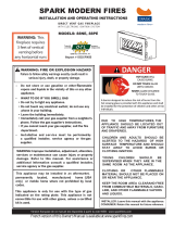
FBB20 BLOWER INSTALLATION
1
1
2
BLOWER ASSEMBLY PARTS LIST
Index
No.
Part
No.
Description Qty.
1 35727 Blower Assembly - Single 2
2 R12390 Wire Harness 1
TOOLS NEEDED:
• 5/16 inch Nut Driver or Screw Gun
CAUTION
Sharp edges. Use gloves when installing these blowers.
INSTALLATION - PRIOR TO SETTING FIREPLACE INTO
FINAL POSITION
1. Unpack the FBB20 Blower assembly.
2. Using a 5/16 inch hex drive, remove the 11 screws holding
rear blower access cover plate, then lay the access plate on
theoor.See Figure 1.
Figure 1
3.
Usearagtowipetheinsidebottomofthereplace(wherethe
blowers will be placed) to remove dirt or construction dust.
4. Placeblowersontheoorbehindthereplace.Position
the blowers with the two black connecting wires and green
ground wire towards the left hand side when facing the back
ofthereplace.See Figure 2.
Figure 2
5.
Locate the blower wire terminals inside the bottom of the
replaceandmakethethreeconnectionsasshownin
Figure 3.
Figure 3

41352-0-0120 Page 9
FBB20 BLOWER INSTALLATION (CONT’D)
6. Begin installing the left blower assembly into the bottom of
thereplace.Oncetheblowerisabouthalfwayin,secure
wiring within the white plastic wire retention clips provided in
thereplace.See Figure 4.
Figure 4
7. Finish installing the left blower so that the left edge of the
blower base bracket is about even with the left edge of the
access opening. Route the wiring away from the blower
wheel. See Figure 5.
Figure 5
8. Next, install the right hand blower assembly towards the
right side of the access opening. The right hand edge of the
blower base bracket should be about even with the right
edge of the access opening. Route wiring away from the
blower wheel. See Figure 6.
Figure 6
9.
Snap the wire harness into the white plastic wire retention clip
locatedatthecenterbottomofthereplace.See Figure 7.
Figure 7

41352-0-0120Page 10
FBB20 BLOWER INSTALLATION (CONT’D)
10. Make sure the blower base brackets are pulled rearward
againstthebottomangeofthereplace.Themagnetson
the blower base bracket will keep the blowers in place. See
Figure 8.
Figure 8
11. Re-attach the Blower Access Panel with the 11 screws
removed in step 2. See Figure 1.
12. Blower installation is complete.

41352-0-0120 Page 11
FIREPLACE DIMENSIONS
INDEX
LETTER
DIMENSION DESCRIPTION
DVLL36BP9 DVLL48BP9
(Dimensions In Inches)
A Themaximumheightofreboxface(excludingstandoffs) 34-1/4 34-1/4
B Themaximumwidthofthereboxface(excludingnailinganges) 49 61
C Themaximumdepthoftherebox 19-1/2 19-1/2
D Theheightofthereboxopening 18 18
E Thewidthofthereboxopening 40-1/4 52-1/4
F Theinteriordepthoftherebox(notshown)
13 13
G Therearexteriorwidthoftherebox 49 61
H Theheighttothereboxstandoffs 49-3/8 49-3/8
I Width from the left side of the box to the centerline of vent 24-9/16 30-9/16
J Depth from back of box to centerline of top vent 7-1/8 7-1/8
K Height from the bottom of the box to the gas line opening 14-3/4 14-3/4
L Depth from the front of the box to gas line opening 14-11/16 14-11/16
M Depth from rear of box to gas line opening 3-3/4 3-3/4
N Glass height 13 13
O Glass width 36 48
P Depth from front of box to centerline of vent 12-3/8 12-3/8
Q Distancefromoortoreplaceopening 7-3/8 7-3/8
R Heightfromoortoventcollar 35-15/16 35-15/16
S Overall height to header 49-1/2 49-1/2
T Distance between framing bracket ends 57-1/16 69-1/16
U Interiorrearwidthofrebox(notshown) 33 45
V Bottomofreplacetoscreenopening 10-1/8 10-1/8
X Top Panel Height 8-3/4 8-3/4
Y Bottom Panel Height 7-5/16 7-5/16
G
I
J
P
C
E
S H
V
N
Y
X
O
B
T
Q
D A
L M
K
R

41352-0-0120Page 12
CLEARANCES
CLEARANCE TO COMBUSTIBLES
Back See Figure 10
Side 3 inch
Floor 0 inch
Top Stand-off Bracket 0 inch
Top Framing Edge 16 inch
SEE MANTEL CHART FOR
MAXIMUM MANTEL DEPTH
16” MIN.
2” X 4” HEADER
STAND-OFF
16” (76mm) HEIGHT
ABOVE TOP OF FIREPLACE
FINISHED WALL
(COMBUSTIBLE)
NON-COMBUSTIBLE
BOARD
TOP FRAMING LEDGE
SEE MANTEL CHART
FOR MINIMUM HEIGHT
OF MANTEL ABOVE
UNIT OPENING
BARRIER
SCREEN/GLASS
FRONT
NOTE A: See Figure 12 for maximum mantel depth and
minimumheightabovereplace.
Figure 9
8”
3”
3” 2”
NOTE: COMBUSTIBLE MATERIALS ALLOWED IN SHADED AREA
3”
Figure 10
Theminimumclearancefrombottomofthereplacetoceiling
is 65 inch.
Theminimumclearancefromsideofthereplaceopeningto
adjacent sidewall is 8 inch.
8” MIN.
(20cm)
TO BOTTOM
OF CABINET
CEILING
TO BOTTOM OF
VENTED OPENING
57
5
/8” MIN
(146cm)
65” MIN
(165cm)
Figure 11
MANTEL CHART
TOP EDGE OF
FIREPLACE OPENING
H
22”
34”
12”
A
3”
MINIMUM
NON-COMBUSTIBLE MATERIAL ZONE
INDEX
LETTER
DISTANCE FROM
FIREPLACE OPENING
(In Inches)
DISTANCE FROM
FINISHED WALL
(In Inches)
A 34 12
B 34 10
C 32 8-3/8
D 30 6-5/8
E 28 5
F 26 3-3/8
G 24 1-3/4
H 22 0
Figure 12
TELEVISION CONSIDERATIONS
Installingatelevisionaboveareplacehasbecomeincreasingly
popular;however,theareaaboveanyreplacegetshotandmost
TV manufacturers recommend against placing their products
near a heat source.
Ifyouinstallatelevisionabovethisreplace,EmpireComfort
Systems accepts no responsibility for damage or injuries. Follow
the television manufacturer’s installation instructions, including any
recommendations regarding proximity to heat sources.
IfyouhaveaTVaboveyourreplace,turnoffthereplaceandletit
cool completely before servicing or touching any buttons on the TV.

41352-0-0120 Page 13
Figure 13
NOTE: Island and Room Divider installation is possible as long as
the horizontal portion of the vent system does not exceed 20 feet
with a minimum vertical run of 8 feet. See details in Venting Section.
NOTE:Wheninstallingthisreplaceagainstanexteriorwall,insulate
to applicable insulation codes.
When you install your Direct Vent Fireplace in Room divider or Flat
on wall corner positions, a minimum of 8 inches clearance must
be maintained from the perpendicular wall and the front opening
ofthereplace.
LOCATING FIREPLACE
ROOM DIVIDER
INSTALLATION
FLUSH WALL
INSTALLATION
ISLAND
INSTALLATION
CABINET
INSTALLATION
CORNER
INSTALLATION
ANGLED CORNER
INSTALLATION

41352-0-0120Page 14
Termination clearance for buildings with combustible and noncombustible exteriors.
VERTICAL SIDEWALL INSTALLATIONS
Important! Minimum clearance between vent pipes and
combustible materials is 3 inch (76 mm) on top, and 1
inch(25 mm) on bottom and sides.
Important! When vent termination exits through foundation less
than 20 inch (508 mm) below siding outcrop, the vent pipe must
extend outward so that the horizontal vent termination is located
ushto,orbeyondtheoutcropsiding.
Information on Various Venting Routes and Components
Important:Itisalwaysbesttolocatethereplaceinsuchaway
that minimizes the number of offsets and horizontal vent length.
Since it is very important that the venting system maintain its
balancebetweenthecombustionairintakeandtheuegas
exhaust,certainlimitationsastoventcongurationsapplyand
must be strictly adhered to.
Figure 14
VENT TERMINATION CLEARANCES
The graph showing the relationship between vertical and
horizontal side wall venting will help to determine the various vent
lengths allowable.
The horizontal vent run refers to the total length of vent pipe from
theuecollarofthereplacetothefaceoftheouterwall.
Venting termination shall not be recessed into wall or siding.
ATTENTION: Vinyl Soft, Vinyl Ceiling, Vinyl Overhang
Disclaimer
Clearances are to heat resistant material (i.e. wood, metal). This
does not include vinyl. Empire Comfort Systems Inc. will not be
held responsible for heat damage caused from terminating under
vinyloverhangs,vinylceilingsorvinylventilated/unventilatedsofts.
RECESSED LOCATION
OUTSIDE CORNER
INSIDE CORNER
“A”= COMBUSTIBLE 9” (229mm)
= NONCOMBUSTIBLE 2” (51mm)
“F”= COMBUSTIBLE 6” (152mm)
= NONCOMBUSTIBLE 6” (152mm)
BALCONY
WITH PERPENDICULAR SIDE WALL
BALCONY
WITH NO SIDE WALL
“C”= CLEARANCE FROM CORNER
IN RECESSED LOCATION
COMBUSTIBLE 9” (229mm)
NONCOMBUSTIBLE 2” (51mm)
“D”= MINIMUM WIDTH FOR BACK WALL
OF A RECESSED LOCATION
COMBUSTIBLE 38” (965mm)
NONCOMBUSTIBLE 24” (610mm)
“E”= MAXIMUM DEPTH OF 48” (1219mm)
FOR RECESSED LOCATION
“G”= COMBUSTIBLE 9” (229mm)
= NONCOMBUSTIBLE 2” (51mm)
“H”= COMBUSTIBLE 18” (457mm)
= NONCOMBUSTIBLE 12” (305mm)
“I” = COMBUSTIBLE 12” (457mm)
= NONCOMBUSTIBLE 12” (305mm)

41352-0-0120 Page 15
VENT TERMINATION CLEARANCES (CONT’D)
Canadian Installations1 US Installations2 Canadian Installations1 US Installations2
A= Clearance above grade,
veranda, porch, deck, or
balcony
12 in (30 cm) 12 in (30cm)
I= Clearance to service
regulator vent outlet 3 ft (91 cm) 6 ft
B= Clearance to window or
door that may be open
6 in (15 cm) for
appliances≤10,000Btuh
(3 kW), 12 in (30 cm) for
appliances > 10,000 Btuh
(3kW)and≤100,000
Btuh (30 kW), 36 in (91
cm) for appliances >
100,000 Btuh (30 kW)
6 in (15 cm) for
appliances≤10,000Btuh
(3 kW), 9 in (23 cm) for
appliances > 10,000 Btuh
(3kW)and≤50,000
Btuh (15 kW), 12 in
(30 cm) for appliances >
50,000 Btuh (15 kW)
J= Clearance to nonme-
chanical air supply
inlet to building or the
combustion air inlet to
any other appliance
6 in (15 cm) for
appliances≤10,000Btuh
(3 kW), 12 in (30 cm) for
appliances > 10,000 Btuh
(3kW)and≤100,000
Btuh (30 kW), 36 in (91
cm) for appliances >
100,000 Btuh (30 kW)
6 in (15 cm) for
appliances≤10,000
Btuh (3 kW), 9 in (23 cm)
for appliances > 10,000
Btuh(3kW)and≤
50,000 Btuh (15 kW), 12
in (30 cm) for appliances
> 50,000 Btuh (15 kW)
C= Clearance to
permanently
closed window
12 in (30 cm) 12 in (30 cm)
K= Clearance to a mechani-
cal air supply inlet 6 ft (1.83 m)
3 ft (91 cm) above
if within 10 ft (3 m)
horizontally
D= Vertical clearance
ventilatedsoftlocated
above the terminal within
a horizontal distance of 2
feet (61 cm) from the
center line of the terminal
24 in (61 cm) 24 in (61 cm)
L= Clearance above paved
sidewalk or paved drive-
way located on public
property
7 ft (2.13 m) † 7 ft (2.13 m) †
E= Clearance to
unventilatedsoft 12 in (30 cm) 12 in (30 cm)
M= Clearance under
veranda, porch deck,
or balcony
12 in (30 cm) ‡ 12 in (30 cm) ‡
F= Clearance to outside
corner
6 in (15 cm) 6 in (15 cm)
1 In accordance with the current CSA B149.1, Natural Gas and Propane
Installation Code
G= Clearance inside corner 9 in (23 cm) 9 in (23 cm) 2 I
n Accordance with the current ANSI Z223.1/NFPA 54, National Fuel Gas Code
H= Clearance to each side
of center line extended
above meter/regulator
assembly
3 ft (91 cm) within a
height 15 ft (4.5 m)
above the meter/regula-
tor assembly
3 ft (91 cm)
† A vent shall not terminate directly above a sidewalk or paved driveway that
is located between two single family dwellings and serves both dwellings
ATTENTION: Vinyl Soft, Vinyl Ceiling, Vinyl Overhang
Disclaimer
Clearances are to heat resistant material (i.e. wood, metal). This
does not include vinyl. Empire Comfort Systems Inc. will not be
held responsible for heat damage caused from terminating under
vinyloverhangs,vinylceilingsorvinylventilated/unventilatedsofts.
‡ Permitted only if veranda,, porch, deck, or balcony is fully open on a mini-
mumoftwosidesbeneaththeoor.
* ForclearancesnotspeciedinANSIZ223.1/NFPA54orCSAB149.1,one
of the following shall be indicated:
Clearance in accordance with local installation codes and the requirements of the
gas supplier.

41352-0-0120Page 16
GAS SUPPLY
The gas pipeline can be brought in through the right side of the
replace.ConsultthecurrentNationalFuelGasCode,ANSI
Z223.1 CAN/CGA-B149 (.1 or .2) installation code.
NOTICE:Neveruseplasticpipe.Checktoconrmwhetheryour
local codes allow copper tubing or galvanized.
NOTICE: Since some municipalities have additional local codes, it
is always best to consult your local authority and installation code.
The use of the following gas connectors is recommended:
— ANSI Z21.24 Appliance Connectors of Corrugated Metal
Tubing and Fittings.
— ANSI Z21.45 Assembled Flexible Appliance Connectors of
Other Than All-Metal Construction
The above connectors may be used if acceptable by
the authority having jurisdiction. The Commonwealth of
Massachusettsrequiresthataexibleapplianceconnector
cannot exceed three feet in length.
Figure 15
GAS SUPPLY PRESSURE (Inches w.c.)
Minimum Normal Maximum
Natural Gas 4.5 7.0 14.0
Propane Gas 10.8 11.0 14.0
MANIFOLD PRESSURE (Inches w.c.)
Normal (HI)
Natural Gas 3.5
Propane Gas 10.0
A gas valve and ground joint union should be installed in the gas
line upstream of the gas control to aid in servicing. It is required
by the National Fuel Gas Code that a drip leg be installed near the
gas inlet. See Figure 16. This should consist of a vertical length of
pipe tee connected into the gas line that is capped on the bottom
in which condensation and foreign particles may collect.
Figure 16
INSTALLING A NEW MAIN GAS SHUT-OFF VALVE
(CHECK LOCAL CODE)
Eachreplaceshouldhaveitsownmanualgasshut-offvalve.
A manual main gas shut-off valve should be located in the vicinity
ofthereplace.Wherenoneexists,orwhereitssizeorlocation
is not adequate, contact your local authorized installer for
installation or relocation.
Compounds used on threaded joints of gas piping shall be
resistanttotheactionofliqueedpetroleumgases.Thegas
lines must be checked for leaks by the installer. This should be
done with a soap solution watching for bubbles on all exposed
connections, and if unexposed, a pressure test should be made.
Never use an epxosed ame to check for leaks. Fireplace
must be disconnected from piping at inlet of control valve
and pipe capped or plugged for pressure test. Never
pressure test with replace connected; control valve will
sustain damage!
NOTICE: The gas control is equipped with a captured screw type
pressure test point, therefore it is not necessary to provide a 1/8
inch test point up stream of the control. See Figure 17.
Whenusingcopperorexconnectoruseonlyapprovedttings.
Thereplaceandit’sindividualshut-offvalvemustbedisconnected
from supply piping system during any pressure testing of that
system at test pressures in excess of 1/2 psig (3.5 kPa).
Thereplacemustbeisolatedfromthegassupplypiping
system by closing its individual manual shut-off valve during any
pressure testing of the gas supply piping system at test pressures
equal to or less than 1/2 psig (3.5 kPa).
Attention! If one of the procedures results in pressures in excess
of1/2psig(14-inw.c.)(3.5kPa)onthereplacegasvalve,itwill
result in a hazardous condition.
GAS
VALVE
GROUND JOINT
UNION
DRIP LEG
3" MINIMUM
SHUT-OFF VALVE
GAS
SUPPLY
INLET
1/8 NPT PLUGGED HOLE
FOR TEST GAUGE
GAS SUPPLY PIPING

41352-0-0120 Page 17
GAS SUPPLY (CONT’D)
CHECKING MANIFOLD PRESSURES
Both Propane and Natural Gas valves have a built-in pressure
regulator in the gas valve. Natural Gas models will have a
manifold pressure of approximately 3.5-in w.c. (.871 kPa) at the
valve outlet with the inlet pressure to the valve from a minimum
of 4.5-in w.c. (1.120 kPa) for the purpose of input adjustment to
a maximum of 14.0-in w.c. (3.484 kPa). Propane Gas models will
have a manifold pressure approximately 10.0-in w.c. (2.49 kPa)
at the valve outlet with the inlet pressure to the valve from a
minimum of 10.8-in w.c. (2.68 kPa) for the purpose of input
adjustment to a maximum of 14.0-in w.c. (3.484 kPa).
CAUTION
If one of the procedures results in pressures in excess of
1/2 psig (14-in w.c.) (3.5 kPa) on the replace gas valve, it
will result in a hazardous condition.
GAS VALV E
OUTLET
PRESSURE
TAP
INLET
PRESSURE
TAP
Figure 17
GAS LINE CONNECTION
Removetheaccesspanelfromtherightsideofthereplace
shown in Figure 18toaccessthegasvalve,gasexline,
junction box, and system wiring.
Attachthegasexlinetothepre-installedgasline.Refertothe
Gas Supply section in this manual for details on the installation
requirements for the gas supply line.
14”
14 5/8
ACCESS PANEL
NAILING FLANGE
JUNCTION BOX
REMOTE WALL
BOX
WIRING EXIT
POINT
GAS LINE
ACCESS
Figure 18

41352-0-0120Page 18
ELECTRICAL CONNECTIONS
CAUTION
All wiring should be done by a qualied electrician and
shall be in compliance with all local, city and state building
codes. Before making the electrical connection, make sure
that the main power supply is disconnected. The replace,
when installed, must be electrically grounded in accordance
with local codes, or in the absence of local codes, with the
National Electrical Code ANSI/NFPA 70 (Latest Edition).
A factory installed junction box is located on the lower right
sideofthereplace.Wiringmustbefedtothejunctionboxand
attached to the receptacle that is provided. Leave approximately
6in of wire in the junction box for connection.
Attach black wire to one side of the receptacle and white wire to
opposite side of receptacle. The ground wire should be attached
to the green (ground) screw. See Figure 19.
BLACK (HOT)
BRASS SCREWS
JUNCTION BOX
GROUND
SILVER SCREWS
GREEN SCREW
WHITE
(NEUTRAL)
120 VOLT POWER SUPPLY
Figure 19
Install the receptacle into the junction box. Attach cover plate.
After the wiring is completed to the junction box and receptacle,
installthejunctionboxtothelowerrightsideofthereplaceas
shown in Figure 20.Insertthetopangeoftheretainerbracket
intotheslotonthereplace.Rotatethejunctionboxassembly
downward, and secure with a screw below the junction box.
See Figure 20.
CONTROL MODULE ACCESS:
To access the control module for servicing, remove the barrier
screen and glass door assemblies. The control module is located
in the bottom right side opening. Remove (1) #10 x 1/2 hex head.
Screws that secures the control cover, then shift the cover to the
left and upward to remove. The control module is located to the
replacebottomwithVelcro®,adncanbelifteduptoaccessthe
module wiring connections.
Figure 20

41352-0-0120 Page 19
Once the Junction box has been installed with the receptacle
outletsfacinginwardtowardsthereplace,locatethe3-prong
power cord from the control module and plug into the receptical.
ThereplaceissuppliedwithaUserInterfacewallboxthatmust
be installed in a standard plastic outlet box (not provided). A low
voltage orange or blue box is recommended. The user interface
wall box must be placed in the wall within ten feet from the right
sideofthereplace.A10feetlongbatteryanduserinterface
extension wire harness is supplied. See Figure 21.
The red and black battery extension harness is connected to
the red and black mating connector pre-installed on the control
module.Thematingconnectorcanbelocatedinsidethereplace
near the gas valve. See Figure 22.
Locate and install the 5/8 inch diameter plastic snap-in grommet
over the low-voltage battery and interface extension harnesses at
therightsideofthereplace.Snapthegrommetintotheholein
thesideofthereplacejustundertheaccesspanelopening.See
Figure 22.
Run the extension wiring to the user interface wall box and
connect the white connector to the remote receiver battery box.
Install the battery box into the wall outlet box, then install the
white remote cover supplied with the provided screws.
WALL MOUNT
CONTROL BOX
6” MIN
10’ MAX WIRE
EXTENSION LENGTH
Figure 21
• Place batteries in remote receiver and in the remote control
using instructions provided. Set the remote switch in wall box
to remote. (center position)
ELECTRICAL CONNECTIONS (CONT’D)
HAND BENT
FLANGE
WIRE
GROMMET
USER INTERFACE HARNESS
& BATTERY EXTENSION
HARNESS
CONNECT TO THE USER INTERFACE/BATTERY
HOLDER. MUST BE INSTALLED IN AWALL
JUNCTION BOX (ORANGE LOW VOLTAGE OR
BLUE BOX RECOMMENDED)
NOTE: OUTER ACCESS DOOR REMOVED. REPLACE AFTER ALL
WIRE AND GAS CONNECTIONS HAVE BEEN MADE
Figure 22
NOTE: OUTER ACCESS
DOOR REMOVED.
REPLACE AFTER
ALL WIRE AND GAS
CONNECTIONS HAVE
BEEN MADE.
USER INTERFACE HARNESS
AND BATTERY EXTENSION
HARNESS
CONNECT TO THE USER
INTERFACE/BATTERY
HOLDER. MUST BE INSTALLED
IN A WALL JUNCTION BOX
(ORANGE LOW VOLTAGE OR
BLUE BOX RECOMMENDED).

41352-0-0120Page 20
INSTALLATION
FRAMING
This replace can be elevated off the oor provided that the
replace is properly supported by framing materials and the
ceiling clearances are maintained.
Fireplaceframingcanbebuiltbeforeorafterthereplaceisset
in place. Framing should be positioned to accommodate wall
coveringandreplacefacingmaterial.Thereplaceframing
should be constructed of 2 x 4 lumber. Refer to Figure 23 for
minimum framing dimensions.
CAUTION
Measure replace dimensions and verify framing methods,
and wall covering details before framing construction begins.
Framing dimension A includes a 16 inch clearance for
framing standoffs on replace. After installing replace
into framing, the non-combustible board must cover the
16 inch opening above the replace.
NOTICE:Fornishingtotopofreplace,refertoFigures 32
and 33.
B
C
A
C
INDEX NO. DVLL36 DVLL48
A 49-1/2 inch 49-1/2 inch
B 55-5/8 inch 67-5/8 inch
C 21-1/2 inch 21-1/2 inch
Figure 23
CONSTRUCTION OF A FIREPLACE CHASE
A chase is a vertical box-like structure built to enclose the gas
replaceand/oritsventsystem.Incoolerclimatesthevent
should be enclosed inside the chase.
NOTICE: Treatment of ceiling restops and wall shield restops
and construction of the chase may vary with the type of building.
These instructions are not substitutes for the requirements of
local building codes. Therefore, you MUST check local building
codes to determine the requirements to these steps.
A chase should be constructed in the manner of all outside walls
of the home to prevent cold air drafting problems. The chase
should not break the outside building envelope in any manner.
Walls,ceiling,baseplateandcantileveroorofthechaseshould
beinsulated.Vaporandairinltrationbarriersshouldbeinstalledin
the chase as per regional codes for the rest of the home.
Additionally,inregionswherecoldairinltrationmaybeanissue,
the inside surfaces may be sheet rocked and taped (or an
equivalent method may be used) to achieve maximum air tightness.
Tofurtherpreventdrafts,thewallshieldandceilingrestops
should be caulked with caulk rated for a minimum of 300°F
continuous exposure rating to seal gaps. Gas line holes and
other openings should be caulked or stuffed with unfaced
insulation.Ifthereplaceisbeinginstalledonacementsurface,
a layer of plywood may be placed underneath to prevent
conducting cold up into the room.
FRAMING AND FINISHING
1. Choosereplacelocation.Seepages14-15.
2. Frameinreplacewithaheaderacrossthetop.Itis
importanttoallowfornishedfacewhensettingthedepthof
thereplace.
3. Secure the four framing brackets and hand bend them into a
V shape as shown in Figure 24. Secure with #10 x 1/2 inch
hex-head screws.
4. Locatethenailingangesonthesidesofthereplace(two
each side). See Figure 24.
Figure 24
5. Securereplacetoframingwithnailinganges.Presetdepth
tosuitfacingmaterial(ushor1/2inchsetbackdepths).
See Figure 25.
NAILING FLANGES
SECURED TO
FRAMING
Figure 25
/