Page is loading ...

P/N 30-3510
2001–2006 BMW E46 M3
Manual Transmission
Plug & Play Adapter Harness
AEM Performance Electronics
AEM Performance Electronics, 2205 126th Street Unit A, Hawthorne, CA 90250
Phone: (310) 484-2322 Fax: (310) 484-0152
http://www.aemelectronics.com
Instruction Part Number: 10-3510
Document Build 2017-09-27
Instruction
Manual
STOP!
THIS PRODUCT HAS LEGAL RESTRICTIONS.
READ THIS BEFORE INSTALLING/USING!
THIS PRODUCT MAY BE USED SOLELY ON VEHICLES USED IN SANCTIONED COMPETITION WHICH MAY NEVER BE USED UPON A
PUBLIC ROAD OR HIGHWAY, UNLESS PERMITTED BY SPECIFIC REGULATORY EXEMPTION. (VISIT THE “EMISSIONS” PAGE AT
HTTP://WWW.SEMASAN.COM/EMISSIONS FOR STATE BY STATE DETAILS.)
IT IS THE RESPONSIBILITY OF THE INSTALLER AND/OR USER OF THIS PRODUCT TO ENSURE THAT IT IS USED IN COMPLIANCE WITH
ALL APPLICABLE LAWS AND REGULATIONS. IF THIS PRODUCT WAS PURCHASED IN ERROR, DO NOT INSTALL AND/OR USE IT. THE
PURCHASER MUST ARRANGE TO RETURN THE PRODUCT FOR A FULL REFUND.
THIS POLICY ONLY APPLIES TO INSTALLERS AND/OR USERS WHO ARE LOCATED IN THE UNITED STATES; HOWEVER CUSTOMERS
WHO RESIDE IN OTHER COUNTRIES SHOULD ACT IN ACCORDANCE WITH THEIR LOCAL LAWS AND REGULATIONS.
WARNING: This installation is not for the tuning novice! Use this system with EXTREME caution! The AEM
Infinity Programmable EMS allows for total flexibility in engine tuning. Misuse or improper tuning of this
product can destroy your engine! If you are not well versed in engine dynamics and the tuning of engine
management systems DO NOT attempt the installation. Refer the installation to an AEM-trained tuning
shop or call 800-423-0046 for technical assistance.
NOTE: All supplied AEM calibrations, Wizards and other tuning information are offered as potential
starting points only. IT IS THE RESPONSIBILITY OF THE ENGINE TUNER TO ULTIMATELY CONFIRM IF THE
CALIBRATION IS SAFE FOR ITS INTENDED USE. AEM holds no responsibility for any engine damage that
results from the misuse or mistuning of this product!

2
© 2017 AEM Performance Electronics
P/N 30-3510
OVERVIEW
The 30-3510 AEM Infinity Adapter Kit was designed for the 2001–2006 BMW E46 M3 with manual
transmission. This is a true standalone system that eliminates the use of the factory BMW DME (ECU).
The use of this adapter makes the kit “plug and play” so no cutting or splicing wires is necessary. The
base configuration files available for the Infinity EMS are starting points only and will need to be modified
for every specific application. Included in these instructions are descriptions of important differences
between using the factory BMW DME and using the AEM Infinity ECU.
The available AEM Infinity EMS part numbers for this adapter kit are:
· 30-7109 INFINITY 708
· 30-7105 INFINITY 710
NOTE: The Infinity 710 EMS has 2 extra ignition coil and injector outputs for a total of 10 each. These
are sold separately from this adapter kit.
INFORMATION ON INFINITY ECUS USED ON 2005–06 BMW E46 M3’S EQUIPPED WITH FACTORY
COMPETITION PACKAGE:
When the Infinity is used on 2005–06 model year E46 M3s, the DSC lamp will remain illuminated when
the key is in the “on” position. Certain CAN bus features of the Infinity are not available via the steering
wheel cruise control buttons, as these vehicles did not come with factory cruise control buttons. (The
features integrated through CAN bus can be added using an ancillary trim position switch.)
GETTING STARTED
Refer to the 10-7100 for EMS 30-7100 Infinity Quick Start Guide for additional information on getting
the engine started with the Infinity EMS. E46 BMW M3 base session is located in C:
\Documents\AEM\Infinity Tuner\Sessions\Base Sessions
DOWNLOADABLE FILES
Files can be downloaded from www.aeminfinity.com. An experienced tuner must be available to configure
and manipulate the data before driving can commence. The Quick Start Guide and Full Manual describe
the steps for logging in and registering at www.aeminfinity.com. These documents are available for
download in the Support section of the AEM Electronics website:
http://www.aemelectronics.com/products/support/instructions
Downloadable files for 2001–2006 BMW E46 M3
· 7105-XXXX-64 Infinity 710 BMW E46 (XXXX = serial number)
· 7109-XXXX-65 Infinity708 BMW E46 (XXXX = serial number)
NOTE: The Flash Enable connector (described in the following pages) MUST be “jumped” in
order to connect to the Infinity and load the initial firmware file. Subsequent firmware
upgrades will not require this step.
§ Ignition key OFF
§ Insert zip-tied jumper shunt connector into Flash Enable connector
§ Ignition key ON (RUN position)
§ Infinity Tuner | Target | Upgrade Firmware… | Upload downloaded .pakgrp file
§ Disconnect Flash Enable jumper connector
§ Infinity Tuner | File | Import Calibration Data | Select appropriate base session file

2001–2006 BMW E46 M3
3
© 2017 AEM Performance Electronics
OPTIONS
30-2001 UEGO Wideband O2 Sensor
Bosch LSU4.2 Wideband O2 Sensor that connects to AEM 30-3600 UEGO Wideband O2 Sensor
Extension Harness
30-3600 UEGO Wideband O2 Sensor Extension Harness
Extension harness to connect AEM UEGO Wideband O2 sensor to 6-pin Deutsch
30-3602 IP67 Logging Cable
USB A-to-A extension cable: 39” long with right angled connector and bayonet style lock
INFINITY CONNECTORS
The AEM Infinity EMS uses the MX123 Sealed Connection
System from Molex. AEM strongly recommends that users
become familiar with the proper tools and procedures for
working with these high density connectors before
attempting any modifications. The entire Molex MX123
User Manual can be downloaded direct from Molex at:
http://www.molex.com/mx_upload/family//MX123UserManu
al.pdf

4
© 2017 AEM Performance Electronics
P/N 30-3510
INFINITY ADAPTER HARNESS
Included with the BMW E46 M3 kit is an adapter harness. This is used to make the connection between
the AEM Infinity EMS and the BMW wiring harness plug and play. This is depicted below with the 73-pin
and 56-pin connectors and the BMW M3 header. There are also a few other integrated connectors within
this harness described below.
The gray Deutsch 6P DTM “Lambda #1” and “Lambda #2” plugs are for connecting UEGO wideband
Bosch LSU4.2 sensors (AEM 30-2001). The UEGO extension harness (AEM 30-3600) mates the
adapter harness to the sensor (1 required for each sensor used). Note: Even though the BMW S54
engine architecture is inline, the stock exhaust system pairs the cylinders (1,2,3 and 4,5,6) into 2
separate banks. For this case, 2 sensors are recommended. If a single turbocharger is used, 1 sensor is
sufficient.
The gray Deutsch 4P DTM connector is used for “AEMNet”. AEMNet is an open architecture based on
CAN 2.0 which provides the ability for multiple enabled devices, such as dashboards, data loggers, etc.,
to easily communicate with one another through two twisted cables (CAN+/CAN-).
The black Delphi 2-pin “Flash Enable” connector is used for secondary hardware flashing. The included
shunt connector jumps the 2 wires together. Once initially flashed, the EMS is normally upgraded in the
software, not using this connector.

2001–2006 BMW E46 M3
5
© 2017 AEM Performance Electronics
The gray Deutsch 12P DTM “Auxiliary”
connector (shown below) is used to
adapt many common ancillary inputs and
outputs easily. Included in the kit are a
DTM 12P mating connector, 12 DTM
terminals, and a DTM 12P wedgelock. If
used, these components will need to be
terminated by the installer or end user
with 16–22awg wire (not included). Note:
the pin numbering is molded into the
connector, as shown.
Below is a description of each of the
available input/output found in the BMW
specific “Auxiliary” connector.
Available I/O
Typical Use
Notes
Component
Wiring
Fuel Press
This is used for monitoring
fuel pressure input to the
Infinity. It can also be used
to increase or decrease
injector fuel pulse to
compensate for a failing
fuel pump.
Typical electronic fuel
injection fuel pressure
varies 30–100psi.
AEM carries 0–5V
fuel pressure
sensors (sold
separately).
This wire goes
directly to the signal
wire of the pressure
sensor.
Air Temp
Air temperature is typically
used for fuel and ignition
timing correction.
The S54 comes
standard with a MAF
sensor which has an
integrated intake air
temperature sensor.
This wire is run in
parallel with the stock
sensor. This means if
an aftermarket sensor
is to be wired using this
pin, the factory MAF
sensor must be
disconnected or else
the signal will be
skewed drastically.
AEM carries air
temperature sensors
(sold separately).
However, the Infinity
can accept any
thermistor sensor
and can be
calibrated in the
Infinity Tuner
software.
Intake air temp
sensors have two
wires with no polarity.
Sensor Ground
Isolated ground for inputs.
This is not the same as
a power ground or
chassis ground.
This is shared for
the Fuel Press, Air
Temp, MAP
(Manifold Press),
Ethanol Sensor,
etc.
This should be wired
to the ground pin of
the follow ing: Fuel
Press, Air Temp,
MAP, and Ethanol
Sensor.
5V Reference
5 volt supply for the
following aux inputs.
When measured with a
voltmeter, it is normal to
not measure exactly
5V.
This is shared for
the Fuel Press,
MAP (Manifold
Press), and
Ethanol Sensor
inputs.
This should be wired
to the voltage
reference pin of the
following: Fuel
Press, MAP, and
Ethanol Sensor.

6
© 2017 AEM Performance Electronics
P/N 30-3510
Available I/O
Typical Use
Notes
Component
Wiring
MAP (Manifold
Press)
Manifold pressure is used
for speed density fuel
calculation, ignition timing
correction, 02 feedback,
boost control, variable
valve control, ancillary
outputs, etc.
Electronic fuel injection
is calculated in absolute
pressure not gauge
pressure.
AEM carries MAP
sensors (sold
separately).
However, the Infinity
can accept any 0–
5V pressure sensor
and can be
calibrated in the
Infinity Tuner
software.
This should be wired
directly to the MAP
sensor's signal pin.
Ethanol Sensor
This is used for customers
who are converting their
vehicle to utilize ethanol
fuels such as E85 or E98.
This digital input can be
used for other functions
as well.
The GM Fuel
Composition Sensor
(FCS) is the most
commonly used for
converting a vehicle
to flex fuel.
This pin needs to be
wired directly to the
signal pin of the fuel
composition sensor.
Boost Control
Solenoid
This is used to operate a
12V PWM solenoid.
Boost control solenoids
can be normally open
(NO) or normally closed
(NC). This will change
the duty cycle strategy
but is also depends
upon how the
wastegate is plumbed
with hoses.
AEM carries boost
control solenoids
(sold separately).
However, the Infinity
can control most
factory boost control
solenoids.
Solenoids have two
wires and have no
polarity.
Power from
Relay
Can be used for many
things, however, this 12V
source was implemented
to be paired w ith the
Boost Control Solenoid.
This 12V is coming
through the vehicle's
main relay.
Because of using
shared power, this
should only be used
for low current
electronics.
N/A
High Side
Output
Can be used to activate the
12V side of a solenoid
If attempting to drive a
component over 4amps,
a relay must be used.
The Infinity can
directly drive an
electronic
component up to
4amps max, such as
a boost solenoid.
For a relay, this
should be wired to
terminal 86 (or 85).
Supply chassis
ground to the opposite
terminal 85 (or 86). If
directly driving a low
current component,
wire this to the 12V
terminal.
Boost Target
Trim Selector
Input
Can be used for to trigger
multiple boost targets.
This analog input can be
used for other functions
as well.
AEM 12 Position
Universal Trim Pot
(or typical
potentiometer). Can
also be used with
any simple ON/OFF
switch.
This wire should be
routed to the signal
output of the
component. If used
with a simple ON/OFF
switch, route the
opposite terminal to an
Infinity sensor ground.

2001–2006 BMW E46 M3
7
© 2017 AEM Performance Electronics
Available I/O
Typical Use
Notes
Component
Wiring
Radiator Fan 1
Can be used to operate an
auxiliary fan for a radiator,
intercooler, etc.
This low side (ground)
output can be used for
other functions as well.
If attempting to drive a
component over 4amps,
a relay must be used.
The Infinity can
directly drive an
electronic
component up to
4amps max.
For a relay, this
should be wired to
terminal 85 (or 86).
Supply 12V to the
opposite terminal 86
(or 85). If directly
driving a low current
component, wire this
to the ground terminal.
No Lift Shift
Trigger
Cutting fuel and/or cutting
spark and/or retarding
ignition timing when shifting
gears without releasing the
throttle pedal.
Cut time is typically 200-
300mS. Ignition retard is
typically 20degree with
a 50mS ramp-in time
after the fuel cut.
Ignition cut is not
commonly used.
AEM 12 Position
Universal Trim Pot
(or typical
potentiometer). Can
also be used with
any simple ON/OFF
switch.
This wire should be
routed to the signal
output of the
component. If used
with a simple ON/OFF
switch, route the
opposite terminal to an
Infinity sensor ground.
EXHAUST GAS TEMPERATURE SENSOR
The BMW M3 S54 engine uses an exhaust gas temperature sensor (EGT). This is a 0–5V resistive
temperature device (RTD) that is input to the Infinity EMS. AEM has already done the work by calibrating
and entering the EGT data (shown below) into the base session files. There is currently no fuel control,
but this channel can be data logged for tuning purposes.

8
© 2017 AEM Performance Electronics
P/N 30-3510
DRIVE-BY-WIRE THROTTLE CONTROL
The BMW M3 S54 engine uses 6 individual throttle
bodies controlled via drive-by-wire (DBW). It is important
to note that throttle control is a critical system which
needs to be correct, and the BMW E46 throttle and
intake system is a unique implementation with several
details that require careful attention. The basic terms of
drive-by-wire are as follows: the ‘gas pedal’ inside the
passenger cabin is called the Accelerator Pedal
(DBW_APP1%), while the electronically controlled
throttles in the engine bay are referenced as ‘Throttle’ (Throttle%, DBW1_TPSA%). Based on the
measured Accelerator Pedal position, the ECU determines a desired DBW_Target position and moves
the Throttle to that position.
As shown, there is a
Drive By Wire Wizard
which must be used to
calibrate accelerator
pedal and throttle
position sensors.
Although sensor
calibration values from
one vehicle may be
close enough to work
for another vehicle
under some circumstances, it is absolutely necessary to run the Drive By Wire Wizard before running
the engine for the first time. The wizard should be repeated if any components in the throttle control
system are removed or replaced such as the throttle bodies, TPS sensors, throttle linkage, electronic
throttle control motor, or accelerator pedal.
Please ensure the vehicle’s battery is fully charged (at least 12.5 Volts) before running the Drive By Wire
Wizard, as low battery voltage can result in abnormal sensor measurements. If a battery charger is
available, it is preferable to connect the battery charger in 5A, 10A, or 20A mode and perform the Drive
By Wire Wizard while the battery voltage is near 13.5–14.0 Volts. When connected to the Infinity EMS
with the engine OFF, go to Plug-in | Wizards | Drive By Wire Wizard. On the first page, be sure to check
the ‘Calibrate Sensor Data Only’ checkbox before selecting ‘Start’. Follow the step-by-step instructions
for each page.
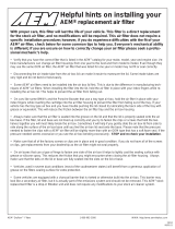
The BMW E46 M3 SPORT button located in the center
console (shown) still serves as a switch input to the
ECU. Contrary to some misinformed beliefs, this button
never changed the maximum power output of the
engine. This switch changes the accelerator-pedal to
throttle-target relationship in the stock BMW DME.
These curves are configurable in the Infinity Tuner
software using the DBW_ThrottleCurve1 /
DBW_ThrottleCurve2 tables, which allow the tuner to define the DBW throttle target based on
Accelerator Pedal Position and Engine Speed.

2001–2006 BMW E46 M3
9
© 2017 AEM Performance Electronics
When accelerator pedal is pressed, idle valve sends more airflow into
engine. Airflow increases when LS5_Duty is set to low values.
The ModeSelect_DBW table is
preconfigured to switch between
the two different
DBW_ThrottleCurve tables,
depending on the status of the
CAN_SPORTBUTTON signal. The
CAN_SPORTBUTTON toggles
between 0 and 1 (2 and 3 are not
used) when depressing the
SPORT button. States 0 and 1 are
mapped to the
DBW_ThrottleCurve1 and
DBW_ThrottleCurve2 tables
respectively. Both 2D tables use
accelerator pedal position for the
y-axis and RPM for the x-axis.
The values that are entered in the
table are throttle position targets.
Between 0-10% accelerator pedal position, the idle valve supplies all airflow to the engine while the
individual throttles remain fully closed. This behavior can be observed in the LS6_Duty table (which
increases airflow through the idle valve when the accelerator pedal is pressed) and the
DBW_ThrottleCurve tables. If tuners desire to adjust the DBW_ThrottleCurve tables, the lower two rows
must remain set to 0. Great care must be taken when adjusting the ThrottleCurve tables, poor choices
here can result in undesirable engine response or drive-by-wire tracking errors.
If it is desired to mimic the OEM BMW throttle control strategy, set the target to 75% throttle below 5500
RPM when the Accel Pedal is 100% open and 90% throttle above 5500 RPM. NOTE: Do not enter
values above 95% in the throttle curve tables; this will force the throttles against the
mechanical ‘full open’ stop which is not desirable and could cause failsafe actions to occur.
Tuning Tool Tip: Because the AEM base session files use TPS as the VE table y-axis, the throttle target
tables can be used as a tuning aid. Simply set the DBW_APP1 100% row to Throttle target values that
correspond to values which need attention in the VE tables. This enables each cell to be accessed
easily by the tuner on a dynamometer for example.
The factory BMW traction control and rev limiter is controlled using the DBW, whereas many other
applications use a fuel cut or, in some rare cases, an ignition cut or ignition retard. With the AEM
Infinity, these can be controlled by any or all of the aforementioned methods.
Note that there is also a
DBW Tuning section in the
Plug-in | Wizards | Setup
Wizard… However, most of
these channels will already
be set up properly in the
AEM base session file and
should not be changed.

10
© 2017 AEM Performance Electronics
P/N 30-3510
There are a few integrated DBW fail safes incorporated into the Infinity system. The ECU constantly
monitors the accelerator pedal sensor voltage and throttle position sensor voltages to ensure the signals
are not excessively high or low due to damaged sensors, short circuits, or broken wires. The ECU also
performs self-diagnostics to ensure the electronic throttle is following desired DBW_Target properly, that
the DBW throttle control motor is not using excessive energy to move the throttle, and watching to see
that all the redundant sensors are working together as expected. If any of these conditions are
determined to be abnormal or unsafe, the ECU can shut the engine down to prevent unintended engine
acceleration. When the ECU shuts the engine off due to problems detected in the DBW system, the
AEM Infinity notifies the driver by illuminating the Engine Malfunction Lamp (EML) on the dashboard. This
error will reset when the ignition key is cycled or if the problem is fixed.
CAN BUS
The AEM Infinity EMS for the BMW E46 M3 supports the majority of the OEM features including:
Tachometer, Oil Temperature Gauge, Coolant Temperature Gauge, A/C Request Button, and Fuel
Consumption (MPG).
When the EMS is connected to a PC and changes are being committed either through table
values or the wizard, the CAN transmission may occasionally pause and the gauges will drop
out one at a time until they all stop working. This does not happen during normal operation.
Cycling the ignition switch will reset everything back.
NOTE: If the vehicle is used on rollers such as a dynamometer where the front wheels and rear wheels
are operating at completely different speeds, the DSC light, the TPMS (tire pressure monitoring system),
and the BRAKE light will illuminate as usual. When the vehicle is driven conservatively on a road, these 3
lights will be OFF like normal. However, if the tires experience any slippage, these 3 lights will flash
ON/OFF, warning the driver of traction issues. If the tires are excessively spun, these 3 lights may stay
ON replicating a dynamometer speed test. If this happens, a simple cycle of the ignition key will reset
these lights back to OFF.
The DSC light is not controlled by the Infinity but by the BMW VDC/ABS controller. The BMW VDC
system, when enabled, may apply brake pressure to one or more of the wheels to maintain
vehicle stability during spirited driving; the DSC light may briefly illuminate or flash during these
events. If excessive wheel slip is encountered then the DSC light may remain illuminated for the

2001–2006 BMW E46 M3
11
© 2017 AEM Performance Electronics
remainder of the current power cycle as the Infinity is not configured to reduce torque during
these events as an OEM ECU might.
Rather than OBD2 diagnostics, the SES-Service Engine Soon light is now dedicated to the AEM
“MILOutput” feature. The AEM MILOutput activates if any 1 of the following inputs are in an error state: air
temp, baro pressure, coolant temp, exhaust back pressure, fuel pressure, UEGO #1, UEGO #2, MAF
analog, MAF digital, MAP, oil pressure, or throttle position. If any of these sensors are not used, they
should be turned OFF in the Wizard to avoid any false readings. To activate the MILOutput feature, go to
the Wizard and check “Enable MIL Output” in Diagnostics.
The red oil can light still illuminates if there is low engine oil pressure. However, it will no longer change
to yellow when the engine oil level is low. But, if an aftermarket oil pressure sensor is installed, the oil
can will illuminate yellow and beep if the AEM failsafe “OilPressProtectOut” is triggered. This feature
needs to be activated in the Engine Protection section of the Wizard, as shown below left. Also, there is
a corresponding RPM dependent “OilPressProtect” 1D Table that needs to be set up as well. When the
oil pressure falls below this set value, the Oil Press Protect feature will be activated.
Rather than OBD2 diagnostics, the EML-Engine Malfunction Lamp on the dash warns the driver if the
“DBW_Error_Fatal” has been activated. If this happens, the engine will be shut down for safety and the
error will reset when the ignition key is cycled and the condition that caused the error is no longer
present.
The coolant temperature gauge’s red warning LED, located in the BMW gauge cluster, is programmable.
When the coolant exceeds the value entered in the channel “CoolantHighLEDLimit” the LED will
illuminate (default = 100C).
The 4000–9000RPM red and yellow tachometer LEDs (shown)
will now always match the current RPM limiter. For example, if
the 2-step rev limiter is active and targeting 5000RPM, the
tachometer LEDs will move the displayed “redline” to 5000RPM.
This happens even if the engine is idling and not actively
banging against the 2-step limiter. If the 2-step rev limiter is
OFF, but the main rev limiter is set to 7000RPM, the LEDs will
show the displayed “redline” at 7000RPM. If the 3-step rev
limiter turns ON and changes the target rev limiter to 6500RPM,
the LEDs will show the displayed “redline” at 6500RPM.
The main rev limiter is configurable in the setup wizard. The 2-
step and 3-step rev limiters are configurable in the setup wizard
and in corresponding tables. Keep in mind, there are fuel cuts,
spark cuts, ignition retards, and cut start windows. The tachometer LEDs are driven by the lower value
between the fuel and spark cuts and ignores the ignition retard and cut start window RPMs.
The following channels on the BMW CAN bus are available for logging. The AEM traction control utilizes
the CAN wheel speed sensors: CAN_FLWS [MPH], CAN_FRWS [MPH], CAN_RLWS [MPH],
CAN_RRWS [MPH]. The following steering channels are only for data logging: CAN_STEERANGLE
[deg].

12
© 2017 AEM Performance Electronics
P/N 30-3510
The rate of fuel consumption (MPG) is
calculated based on injector duty cycle,
injector size, engine speed, etc. The output
display will be close, but keep in mind there are
many factors and variables. To customize and
make completely accurate, there is a trim
channel named “CAN_FUELFLOWSCALER”.
The default value is 0.000864472.

2001–2006 BMW E46 M3
13
© 2017 AEM Performance Electronics
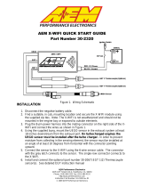
CRUISE CONTROL
Currently, a cruise control feature is not
supported with the AEM Infinity. However,
the multi-functional steering wheel buttons
are run over the BMW MFL bus and are
available for miscellaneous purposes
described below. There are 4 buttons:
Enable, Resume Set, Accelerate+, and
Decelerate- (as shown).
The Enable button now engages the 3-step rev
limiter channel “CAN_CCEnable”. A 3-step rev
limiter is a simplified traction control based
system that uses engine and vehicle speed or
launch timer inputs to limit the RPM of the
engine. To operate, first be sure the
3StepSwitch table is set to recognize the
“momentary” Enable button, as shown. Set
the 3StepTargetFuel and/or the
3StepTargetSpark table’s first (0 MPH) cell to
the desired launch RPM. When the Enable
button is held down, the EMS will limit the
engine’s corresponding RPM. Once the car is launched and the EMS begins to register vehicle speed,
the RPM limit can then be tailored to prevent wheel spin using these tables.
The Resume Set button is used as an
AEM traction control switch. Note:
The DSC button is not available as
it is a direct link to the VDC. The
BMW VDC system is disabled
when using the AEM Infinity. Instead, the latching Resume Set button changes the TC_SlipTargetTrim
1-axis lookup table (shown). Simultaneously, the Cruise Control icon on the dash is illuminated to inform
the driver the status of the programmable AEM traction control. Normally this table is used with a
multiple position switch. However, because the BMW Resume Set button is either OFF (0) or ON (1),
only the first two cells of the table are used. Two possible traction scenarios, for example, could be
ON/OFF or aggressive/nonaggressive. To use this feature, it must be enabled in Infinity Tuner: Plug-Ins |
Wizard | Setup wizard | Traction Control | Traction Control Enable.

14
© 2017 AEM Performance Electronics
P/N 30-3510
The steering wheel’s Accelerate+ and Decelerate-
momentary buttons increment and decrement the map
switching function “CAN_MapValueNV”. This feature is
extremely flexible as it can be used to switch VE
tables, ignition maps, lambda targets, and boost
levels.
When the Accelerate+ or Decelerate- button is
depressed (or when KeyOn occurs) the tachometer
displays 1k, 2K, 3K, 4K, 5K, 6K, 7K, or 8K
momentarily representing the currently selected value
of ModeSwitch. Because of the BMW E46 M3
tachometer range, 1–8 are the only valid values (9–12
are not used for this application).
For safety precautions, the AEM base session files
come standard with the VE tables, ignition maps,
lambda targets, and boost tables all set the same
because the Accelerate+ or Decelerate- button could
be mistakenly bumped.
In order to use this feature, care must be taken into account when setting up the tables and tuning. Enter
the number of the table into the corresponding mode selection table for each feature (VE tables, ignition
maps, lambda targets, and boost levels).
Key Off Commit must be enabled for map position selections, as selected via the cruise control
buttons, to be saved across power cycles. If Key Off Commit is disabled then the map position will
reset to its default position after a power cycle.

2001–2006 BMW E46 M3
15
© 2017 AEM Performance Electronics
INFINITY EMS INSTALLATION
Step 1
Open the trunk and disconnect the
battery.
Open the hood and locate the E-Box on
the left side near the firewall. This is
where the factory ECU (Digital Motor
Electronics or DME) resides.
Remove the four screws using a T25
Torx wrench (late models) or 5mm Allen
wrench (early models). Simultaneously
pull up and rotate the E-Box cover to
release it from the vehicle. This will be
reused.
Step 2
There are 5 DME connectors. These
must be removed in a sequence from the
left to the right (as pictured) or connector
5-4-3-2-1.
First remove connector 5 using your
thumb by squeezing the release tab.
Hold down and pull upwards.

16
© 2017 AEM Performance Electronics
P/N 30-3510
Step 3
Connectors 4, 3 and 2 all have a
swinging latch. First press the “button”
and then rotate the swing latch
downwards towards the DME.
Note: When reinserting connectors into
the header, the swing latch must be
open for initial engagement.
Step 4
The connector will automatically push
itself away from the DME connector’s
header.
After removing connectors 4, 3, and 2,
remove connector 1 the same way as
connector 5 using your thumb.

2001–2006 BMW E46 M3
17
© 2017 AEM Performance Electronics
Step 5
To remove the DME (stock ECU) from
the internal plastic “skeleton”, push the
two tabs away from the bottom side of
the DME, as shown.
Step 6
Simultaneously unlock the plastic tabs
and pull the DME up and out of the
engine bay.
The stock DME will NOT be reused.

18
© 2017 AEM Performance Electronics
P/N 30-3510
Step 7
Next, there will need to be room made
for the AEM Infinity EMS and jumper
box to fit within the E-Box
compartment.
Note: Some of the instructions below
may slightly differ from vehicle to
vehicle.
Unplug the 2 white connectors (shown)
by squeezing each connector’s locking
tabs.
Note: These two connections will be
reconnected later.
Step 8
Using a flat blade, such as a
screwdriver, unlock the black fuse
block’s tab, as shown, and lift upwards.

2001–2006 BMW E46 M3
19
© 2017 AEM Performance Electronics
Step 9
Using a flat blade, such as a
screwdriver, unlock the blue relay’s tab,
as shown, and lift upwards.
Step 10
Using a flat blade, such as a
screwdriver, unlock the lime green
relay’s tab, as shown, and lift upwards.

20
© 2017 AEM Performance Electronics
P/N 30-3510
Step 11
Carefully pull the internal plastic mount
upwards a few inches to unlock it from
the base.
Step 12
Cut the factory cable zip-ties to release
the BMW wiring harness from the
internal plastic mount using a pair of
long-reach dikes.
Cut the zip-tie shown.
/