KitchenAid KODE900HBS Installation guide

Type
Installation guide

This manual is also suitable for

INSTALLATION INSTRUCTIONS 30" (76.2 CM)
ELECTRIC SINGLE ANDDOUBLE BUILT-IN OVEN
INSTRUCTIONS D’INSTALLATION DES FOURS
ENCASTRÉS SIMPLE ET DOUBLE DE 30 PO
(76,2CM)
Table of Contents/Table des matières
IMPORTANT:
Sa
ve for local electrical inspector's use.
IMPOR
TANT :
À conser
ver pour consultation par l'inspecteur local des installations électriques
.
W11047061C
BUILT-IN OVEN SAFETY ................................................................2
INSTALLATION REQUIREMENTS
................................................. 2
Tools and Parts
............................................................................. 2
Location Requirements
................................................................3
Electrical Requirements
...............................................................6
INSTALLATION INSTRUCTIONS
................................................... 7
Prepare Built-In Oven
...................................................................7
Remove Oven Door(s)
..................................................................7
Replace Oven Door(s)
..................................................................8
Positioning Oven Feet for Multiple Cabinet Cutout Heights .......8
Make Electrical Connection
.......................................................13
Install Oven
.................................................................................14
Complete Installation
.................................................................16
SÉCURITÉ DU FOUR ENCASTRÉ
..............................................17
EXIGENCES D’INSTALLATION
...................................................17
Outils et pièces
...........................................................................17
Exigences d’emplacement
.........................................................18
Spécifications électriques
..........................................................21
INSTRUCTIONS D’INSTALLATION
.............................................22
Préparer le four encastré
............................................................22
Enlever la ou les portes du four
.................................................22
Réinstaller la ou les portes du four
............................................23
Positionner les pieds du four pour des ouvertures
de découpe dans l’armoire
........................................................24
Raccordement électrique
...........................................................28
Installer le four
............................................................................30
Terminer l’installation
..................................................................32
2
BUILT-IN OVEN SAFETY
INSTALLATION REQUIREMENTS
Tools and Parts
Gather the required tools and parts before starting
installation.Read and follow the instructions provided
withanytools listed here.
Tools Needed
Phillips screwdriver
Measuring tape
Hand or electric drill (for wall cabinet installations)
1" (2.5 cm) drill bit (for wall cabinet installations)
Level
Flat-blade screwdriver
Parts Needed
UL Listed or CSA Approved conduit connector
UL Listed wire connectors
Warming Drawer Deector Kit (for ovens installed
aboveawarming drawer)
Order Part Number W10536339 for stainless steel
30"76.2cm) kit
Order Part Number W10727416 for black stainless steel
30" (76.2 cm) kit
To order, see the “Assistance or Service” section
oftheUseand Care Guide.
Flush Installation Kit (for Single and Double installed at ush
installation)
Order Part Number W10752683 for stainless steel
30" (76.2 cm) kit
Order Part Number W10752682 for black stainless steel
30" (76.2 cm) kit
To order, see the “Assistance or Service” section of the Use
and Care Guide.
Parts Supplied
#8-14 x
3
/
4
" (1.9 cm) screws - single ovens (2), double
ovens (4)
#8-18 x
3
/
8
" (9.5 mm) screws - bottom vent (2)
#8-18 x
1
/
4
" (6.4 mm) screws - bottom vent trim (4)
#8-18 x
3
/
8
" (9.5 mm) screws - double oven feet (4)
Bottom vent
Rear feet - double oven (2)
Front feet - double oven (2)
Check local codes. Check existing electrical supply. Seethe
“Electrical Requirements” section.
It is recommended that all electrical connections
bemadebyalicensed, qualied electrical installer.
You can be killed or seriously injured if you don't immediately
You
can be killed or seriously injured if you don't
follow
All safety messages will tell you what the potential hazard is, tell you how to reduce the chance of injury, and tell you what can
happen if the instructions are not followed.
Your safety and the safety of others are very important.
We have provided many important safety messages in this manual and on your appliance. Always read and obey all safety
messages.
This is the safety alert symbol.
This symbol alerts you to potential hazards that can kill or hurt you and others.
All safety messages will follow the safety alert symbol and either the word “DANGER” or “WARNING.”
These words mean:
follow instructions.
instructions.
DANGER
WARNING
3
Location Requirements
IMPORTANT: Observe all governing codes and ordinances.
Cabinet opening dimensions that are shown must be used.
Given dimensions provide minimum clearance with oven.
Recessed installation area must provide complete
enclosurearound the recessed portion of the oven.
Grounded electrical supply is required. See the
“ElectricalRequirements” section.
Electrical supply junction box should be located 3" (7.6cm)
maximum below the support surface when the oven is
installed in a wall cabinet. A 1" (2.5 cm) minimum diameter
hole should have been drilled in the right rear or left rear
corner of the support surface to pass the appliance cable
through to the junction box.
NOTE: For undercounter installation, it is recommended
that the junction box be located in the adjacent right or
leftcabinet. If you are installing the junction box on rear
wallbehind oven, it is recommended that the junction box
berecessed and located in the upper center of the cabinet.
Oven support surface must be solid, level, and ush
withbottom of cabinet cutout.
Floor must be able to support a single oven weight of 200lbs
(91 kg)
for 30" (76.2 cm) models.
Floor must be able to support a double oven weight of
330lbs (150 kg)
for 30" (76.2 cm) models.
IMPORTANT: To avoid damage to your cabinets, check
with your builder or cabinet supplier to make sure that the
materials used will not discolor, delaminate, or sustain other
damage. This oven has been designed in accordance with
the requirements of UL and CSA International and complies
with the maximum allowable wood cabinet temperatures
of194°F (90°C).
Undercounter Installation (with Cooktop Installed Above):
Ovens approved for this type of installation have an approval
label located on the top of the oven. Refer to Cutout Dimensions
for Ovens Installed Under Cooktop (separate sheet).
Product Dimensions - Single Ovens
B
C
D
E
A
G
F
30" (76.2 cm) models
A. 28
3
/
4
" (72.8 cm) max. overall height
B. 28
1
/
2
" (72.4 cm) max. recessed width
C. 26
3
/
4
" (67.9 cm) recessedheight
D. 23
1
/
4
" (59.1 cm) max. recessed depth
E. 30" (76.2 cm) overall width
F. 12" (30.5 cm) from back of control
panel to start ofstrain relief
G. 48" (121.9 cm) exible conduit length
4
Cabinet Dimensions - Single Ovens
Single Oven Undercounter (Without Cooktop Installed Above)
Single Ovens Installed in Cabinet
* NOTE: The cutout height can be between 26
15
/
16
" and 29
7
/
16
"
(68.4 cm and 74.8 cm) for single ovens.
A
B
C
D
E
30" (76.2 cm) models
A. 30" (76.2 cm) min. cabinetwidth
B. 1
1
/
2
" (3.8 cm) min. top ofcutout
to underside ofcountertop
C. 5
1
/
4
" (13.3 cm) bottom ofcutout
to oor
D. 28
1
/
2
" (72.4 cm) cutoutwidth
E. 28" (71.2 cm) min. cutoutheight
F
E
B
C
A
D
G
30" (76.2 cm) models
A. 30" (76.2 cm) min. cabinetwidth
B. 1" (2.5 cm) top of cutoutto bottom of
uppercabinet door
C. 32" (81.3 cm) bottom of cutout to oor
D. 28
1
/
2
" (72.4 cm) cutoutwidth
E. 1
1
/
2
" (3.8 cm) min. bottomof cutout to
topofcabinet door
F. 28" (71.2 cm)* recommended
cutoutheight
G. 24" (60.7 cm) cutout depth
5
Product Dimensions - Double Ovens Cabinet Dimensions - Double Ovens
Double Ovens Installed in Cabinet
* NOTE: The cutout height can be between 48
7
/
8
" and 52
3
/
16
"
(124.1 cm and 132.6 cm) for double ovens.
C
A
E
D
B
F
G
30" (76.2 cm) models
A. 51
3
/
16
" (130.0 cm) max. overall height
B. 28
1
/
2
" (72.4 cm) max. recessed width
C. 48
13
/
16
" (124.0 cm) recessed height
D. 23
1
/
4
" (59.1 cm) max. recessed depth
E. 30" (76.2 cm) overall width
F. 12" (30.5 cm) from back of control
panel to start ofstrain relief
G. 66" (167.6 cm) exible conduit length
F
E
A
D
G
B
C
30" (76.2 cm) models
A. 30" (76.2 cm) min. cabinetwidth
B. 1" (2.5 cm) top of cutouttobottom
of uppercabinet door
C. 14
3
/
4
" (37.5 cm) bottom of cutout
to oor is recommended. 4"-14
3
/
4
"
(10.2 cm-37.5 cm) bottom of cutout
to oor is acceptable.
D. 28
1
/
2
" (72.4 cm) cutoutwidth
E. 1
1
/
2
" (3.8 cm) min. bottomofcutout
to topofcabinet door
F. 50
1
/
4
" (127.6 cm)* recommended
cutout height
G. 24" (60.7 cm) cutout depth
6
Electrical Requirements
If codes permit and a separate ground wire is used, it is
recommended that a qualied electrical installer determine
thatthe ground path and the wire gauge are in accordance
withlocal codes.
Check with a qualied electrical installer if you are not
suretheoven is properly grounded.
This oven must be connected to a grounded metal,
permanentwiring system.
Be sure that the electrical connection and wire size are
adequateand in conformance with the National Electrical
Code,ANSI/NFPA 70 — latest edition or CSA Standards C22.
1-94, Canadian Electrical Code, Part 1 and C22.2 No.
O-M91 — latest edition, and all local codes and ordinances.
A copy of the above code standards can be obtained from:
National Fire Protection Association
1 Batterymarch Park
Quincy, MA 02169-7471
CSA International
8501 East Pleasant Valley Road
Cleveland, OH 44131-5575
Electrical Connection
To properly install your oven, you must determine the type
ofelectrical connection you will be using and follow the
instructions provided for it here.
Oven must be connected to the proper electrical voltage and
frequency as specied on the model/serial/rating plate. The
model/serial/rating plate is located under the control panel
on single ovens and under the control panel on the upper
oven cavity on double ovens. See the following illustrations.
A
A
Single Oven
A. Model/serial/rating plate
Double Oven
A. Model/serial/rating plate
Models rated from 7.3 to 9.6 kW at 240 volts (5.4 to 7.4kW
at 208 volts) require a separate 40-amp circuit. Models
ratedat 4.8 kW and below at 240 volts (3.6 kW and below
at208 volts) require a separate 20-amp circuit.
A circuit breaker is recommended.
Connect directly to the circuit breaker box (or fused
disconnect) through exible, armored, or nonmetallic
sheathed, copper cable (with grounding wire). See the
“MakeElectrical Connection” section.
Flexible conduit from the oven should be connected
directlyto the junction box.
Fuse both sides of the line.
Do not cut the conduit. The length of conduit provided
isforserviceability of the oven.
A UL Listed or CSA Approved conduit connector
mustbeprovided.
If the house has aluminum wiring, follow the
procedurebelow:
Connect the aluminum wiring using special connectors
and/or tools designed and UL listed for joining copper to
aluminum.
Follow the electrical connector manufacturer’s recommended
procedure. Aluminum/copper connection must conform with
local codes and industry accepted wiring practices.
Voltage Single Double
240 VAC 5.8 kW 9.6 kW
208 VAC 4.4 kW 7.7 kW
7
INSTALLATION INSTRUCTIONS
Prepare Built-In Oven
1. Decide on the nal location for the oven. Avoid drilling
orcutting into house wiring during installation.
2. To avoid oor damage, set the oven onto cardboard prior
to installation. Do not use handle or any portion of the front
frame for lifting.
3. Remove the shipping materials and tape from the oven.
Remember to keep the corner posts and other materials
thatmay be needed for installation.
4. Remove the hardware package from inside the bag
containing literature.
5. Remove and set aside racks, attachments, and other parts
from insidetheoven.
6. Move oven and cardboard close to the oven’s nal location.
Remove Oven Door(s)
IMPORTANT: Use 2 hands to remove oven door. For double
ovens, repeat the process for each door.
1. Prior to removing the oven door, prepare a surface where
youwill place it. This surface should be at and covered
witha soft blanket, or use the corner posts from your
packaging material.
2. Fully open the oven door.
3. Locate the oven door hinge locks in both corners of the
ovendoor, and rotate the hinge locks toward the oven door
to the unlocked position. If the door hinge lock is not rotated
fully (see illustration B), the door will not remove properly.
Locked
position
Grip here
to rotate.
Unlocked
position
A. Oven door hinge lock in
lockedposition
B. Oven door hinge lock in
partially unlocked position
4. Gently start to close the door. The door will stop at a partially
closed position.
5. Using 2 hands, grasp the edges of the oven door. Close the
oven door slightly past the stop position to take the weight
off of the door hinges, and then pull the oven door up.
6. Pull the oven door toward you, and then remove. You may
need to gently shift door from side to side as you pull.
7. Set the oven door aside on the prepared covered work
surface with the oven door resting on its handle.
8. To continue with the oven installation, go to the
“PositioningOven Feet for Multiple Cabinet Cutout
Heights”section.
WARNING
Excessive Weight Hazard
Use two or more people to move and install oven.
Failure to do so can result in back or other injury.
Door
hinges
8
Replace Oven Door(s)
1. Using 2 hands, grasp side edges of door at the midpoint.
Face the oven cavity.
2. Locate the slots on each side of the oven front frame for
thedoor hinge locks.
3. Using 2 hands, grasp the edges of the oven door. At a 45°
angle, insert the hinges at the same time, and push the oven
door into the oven cavity slot to replace. You may need to
gently shift the door from side to side as you push.
4. Make sure the door hinge notch is engaged on the bottom
ofthe oven cavity slot.
IMPORTANT: Do not close the door at this step or damage
may occur to the door hinge.
5. Lower the oven door to the fully open position. If the oven
door does not open to a full 90°, repeat steps 1 through 3.
6. Locate the oven door hinge locks in the corners of the oven
door, and rotate the hinge locks toward the oven cavity to
the locked position.
Unlocked
position
Locked
position
7. After the door hinges have been locked, gently swing the
door upward to close. The door should not be forced closed.
8. When the hinges are properly installed and the door is
closed, there should be an even gap between the door and
the control panel. If one side of the oven door is lower than
the other, the hinge on that side is not properly installed.
See the “Remove Oven Door” and “Replace Oven Door”
sections.
Positioning Oven Feet for Multiple
CabinetCutout Heights
Single Ovens
The positioning of the oven feet allow a single oven to be
installed in a cutout height between 26
15
/
16
" and 29
7
/
16
" (68.4 cm
and 74.8 cm). Refer to the following instructions to position the
feet for the size of your cabinet cutout.
Cutout Height Is Between 27
5
/
8
" and 28
5
/
8
"
(70.2 cm and 72.7 cm)
The oven feet do not need to be changed. They are
positionedcorrectly as received.
Go to the “Make Electrical Connection” section.
A
A. Slot in the oven cavity for door hinge lock
9
Cutout Height Is Between 26
15
/
16
" and 27
11
/
16
"
(68.4 cm and 70.3 cm)
1. Using 2 or more people, place the oven on its back
onacovered surface.
2. Remove the foot from the right front spacer by removing
the#8-18 x
3
/
8
" (9.5 mm) screw.
NOTE: Do not remove the spacer.
3. In the same manner, remove the feet on the right rear,
leftfront, and left rear of the oven.
4. Using 2 or more people, place the oven in its upright position.
5. Go to the “Make Electrical Connection” section.
Cutout Height Is Between 28
11
/
16
" and 29
7
/
16
"
(72.8 cm and 74.8 cm)
1. Using 2 or more people, place the oven on its back
onacovered surface.
2. Remove the foot from the right front spacer by removing
the#8-18 x
3
/
8
" (9.5 mm) screw.
NOTE: Do not remove the spacer.
3. Rotate the foot 90°, so the short side of the foot
ispositionedtoward the top of the oven.
A
B
C
A. Spacer
B. Foot
C. #8-18 x
3
/
8
" (9.5 mm) screw
A
B
C
A. Spacer
B. Foot
C. #8-18 x
3
/
8
" (9.5 mm) screw
10
4. Reinstall the foot to the spacer using the #8-18 x
3
/
8
"
(9.5 mm) screwpreviously removed.
5. In the same manner, remove, rotate, and reinstall the
feetonthe right rear, left front, and left rear of the oven.
6. Using 2 or more people, place the oven in its upright position.
7. Go to the “Make Electrical Connection” section.
Double Ovens
The positioning of the oven feet allow a double oven to be
installed in a cutout height between 48
7
/
8
" and 52
3
/
16
" (124.1 cm
and 132.6 cm). Refer to the following instructions to position
thefeet for the size of your cabinet cutout.
Cutout Height Is Between 48
7
/
8
" and 50
7
/
16
"
(124.1 cm and 128.1 cm)
The oven feet do not need to be installed. The oven
isconguredcorrectly as received.
NOTE: Do not remove the spacers.
Go to the “Make Electrical Connection” section.
A
A
A. Spacers
11
Cutout Height Is Between 50
1
/
2
" and 51
1
/
8
"
(128.2 cm and 129.9 cm)
1. Using 2 or more people, place the oven on its back
onacovered surface.
2. Install a foot on the left rear spacer using a #8-18 x
3
/
8
"
(9.5 mm) screw.
NOTE: Position the foot so the long side of the foot is facing
toward the top of the oven.
3. In the same manner, install a foot on the right rear of the oven.
4. Install a front foot on the left front spacer using a #8-18 x
3
/
8
"
(9.5 mm) screw.
NOTE: Position the foot so the long side of the foot is facing
toward the inside of the oven.
5. In the same manner, install a front foot on the right front
ofthe oven.
6. Using 2 or more people, place the oven in its upright position.
7. Go to the “Make Electrical Connection” section.
A
B
C
A. Spacer
B. Foot
C. #8-18 x
3
/
8
" (9.5 mm) screw
A
B
C
A. Front foot
B. #8-18 x
3
/
8
" (9.5 mm) screw
C. Spacer
12
Cutout Height Is Between 51
3
/
16
" and 52
3
/
16
"
(130 cm and 132.6 cm)
1. Using 2 or more people, place the oven on its back
onacovered surface.
2. Install a foot on the left rear spacer using a #8-18 x
3
/
8
"
(9.5 mm) screw.
NOTE: Position the foot so the short side of the foot is facing
toward the top of the oven.
3. In the same manner, install a foot on the right rear of the oven.
4. Install a front foot on the left front using a #8-18 x
3
/
8
"
(9.5 mm) screw.
NOTE: Position the foot so the long side of the foot is facing
toward the top of the oven.
5. In the same manner, install a font foot on the right front
oftheoven.
6. Using 2 or more people, place the oven in its upright position.
7. Go to the “Make Electrical Connection” section.
C
B
A
A. Spacer
B. Foot
C. #8-18 x
3
/
8
" (9.5 mm) screw
A
B
C
A. Front foot
B. #8-18 x
3
/
8
" (9.5 mm) screw
C. Spacer
13
Make Electrical Connection
For Double Ovens For Single Ovens
This oven is manufactured with a neutral (white) power
supplywire and a cabinet-connected green (or bare)
groundwiretwisted together.
1. Disconnect power.
2. Feed the exible conduit from the oven through
theopeningin the cabinet.
3. Remove junction box cover if it is present.
4. Install a UL Listed or CSA Approved conduit connector
tothejunction box.
5. Route the exible conduit from the oven to the junction box
through a UL Listed or CSA Approved conduit connector.
6. Tighten screws on conduit connector.
7. See the “Electrical Connection Options Chart” to complete
installation for your type of electrical connection.
Electrical Connection Options Chart
If your home has: Go to section:
4-wire 4-Wire Cable from Home
Power Supply
3-wire 3-Wire Cable from Home
Power Supply
4-Wire Cable from Home Power Supply
IMPORTANT: Use the 4-wire cable from home power
supplyinthe U.S. where local codes do not allow grounding
through neutral, New Branch circuit installations (1996 NEC),
mobile homes and recreational vehicles, new construction,
andinCanada.
1. Connect the 2 black wires (B) together using
aULListedwireconnector.
2. Connect the 2 red wires (C) together using
aULListedwireconnector.
3. Untwist white wire from green (or bare)
groundwirecomingfrom the oven.
4. Connect the 2 white wires (F) together using
aULListedwireconnector.
5. Connect the green (or bare) ground wire (H) from
theovencable to the green (or bare) ground wire
(inthejunction box) using a UL Listed wire connector.
6. Install junction box cover.
WARNING
Electrical Shock Hazard
Disconnect power before servicing.
Use 8 gauge copper wire.
Electrically ground oven.
Failure to follow these instructions can result in death,
fire, or electrical shock.
WARNING
Electrical Shock Hazard
Disconnect power before servicing.
Use 12 gauge copper wire.
Electrically ground oven.
Failure to follow these instructions can result in death,
fire, or electrical shock.
A
A. UL Listed or CSA Approved conduit connector
½"
½"
(1.3 cm)
A
D
F
H
B
C
E
G
I
A. Cable from home power supply
B. Black wires
C. Red wires
D. 4-wire exible conduit
fromoven
E. Junction box
F. White wires
G. UL Listed wire connectors
H. Green (or bare) ground wires
I. UL Listed or CSA Approved
conduit connector
14
3-Wire Cable from Home Power Supply - U.S. Only
IMPORTANT: Use the 3-wire cable from home power
supplywhere local codes permit a 3-wire connection.
1. Connect the 2 black wires (C) together using
aULListedwireconnector.
2. Connect the 2 white wires (D) and the green (or bare) ground
wire (of the oven cable) using a UL Listed wire connector.
3. Connect the 2 red wires (G) together using
aULListedwireconnector.
4. Install junction box cover.
Install Oven
1. Using 2 or more people, lift the oven partially into the cabinet
cutout. Use the oven opening as an area to grip.
NOTE: Push against seal area of the oven front frame when
pushing the oven into the cabinet. Do not push against the
outside edges.
2. Push against the seal area of the front frame to push
theoven into the cabinet until the back surface of the
frontframe touches the front wall of the cabinet.
3. Push oven completely into the cabinet and center the oven
into the cabinet cutout.
4. Remove the tape from black front trims.
Securely fasten the oven to the cabinet using the #8-14 x
¾" (1.9 cm) screws provided.
Insert the screws through hole in black trim aligning with
hole in oven frame. Do not overtighten screws.
B
C
D
E
F
H
G
A
I
A. Cable from home power supply
B. Junction box
C. Black wires
D. White wires
E. Green (or bare) ground
wire(from oven)
F. 4-wire exible conduit
fromoven
G. Red wires
H. UL Listed wire connectors
I. UL Listed or CSA Approved
conduit connector
A. Oven frame
B. Oven frame hole
C. Black trim piece
A
B
C
15
5. The bottom vent and bottom vent trim (required when
theoven is installed with the feet in the tall position)
areshipped in the foam packing at the top of the oven.
To install only the bottom vent, see the following instructions.
To install both the bottom vent and the bottom vent trim
forinstallations with the feet in the tall position, see the
instructions in Step 6.
Align vent tab (B) with oven frame (A) as shown.
Using one #8-18 x
3
/
8
" (9.5 mm) screw (D) on each side of
the venttab (B), fasten the vent securely to the oven.
6. On models with the feet installed in the tall position, the
bottom vent trim must also be installed. See the following
instructions to install.
Flex the upper vent piece (C) away from the lower vent
piece (D) to slide the bottom vent trim (B) between them.
Some force may be required to ex the upper vent trim (C)
away from the lower vent trim (D). Some force may also
be required to ex the bottom vent trim (B) and slide it
into position. Make sure screw holes are properly aligned
between the 2 pieces. See the following illustration.
Install the bottom vent trim (B) to the lower vent piece (D)
using two #8-18 x
1
/
4
" (6.4 mm) screws on each side.
Align vent tab (B) with oven frame (A) as shown.
Using one #8-18 x
3
/
8
" (9.5 mm) screw (E) on each side of
the venttab (B), fasten the vent securely to the oven.
7. Replace the oven racks.
8. Replace the oven door. See the “Replace Oven
Door(s)”section.
9. Check that the door is free to open and close. If it is not,
repeat the removal and installation procedures. See the
“Prepare Built-In Oven” section.
10. Repeat for lower oven door.
11. Reconnect power.
12. The display panel will light and boot up.
13. If the display panel does not light, reference the
“Warranty”section of the Use and Care Guide.
A
B
C
D
A. Oven frame
B. Vent tab
C. Oven vent
D. #8-18 x
3
/
8
" (9.5 mm)
screws
D
A
A
C
B
D
B
C
A. #8-18 x
1
/
4
" (6.4 mm)
screw
B. Bottom vent trim
C. Upper vent piece
D. Lower vent piece
E D C
B
A
A. Oven frame
B. Vent tab
C. Oven vent
D. Bottom vent trim
E. #8-18 x
3
/
8
" (9.5 mm)
screw
16
Complete Installation
1. Check that all parts are now installed. If there is an extra part,
go back through the steps to see which step was skipped.
2. Check that you have all of your tools.
3. Dispose of/recycle all packaging materials.
4. For oven use and cleaning, read the Use and Care Guide.
Check Operation of Single and Double Ovens
1. Turn on power.
2. At rst use, set up the clock and any other preferences
ifavailable. For more information, read the Use and
CareGuide.
3. Start a broil cycle. See the User Instructions for instructions.
NOTE: Odors and smoke are normal when the oven is used
the rst few times.
4. Wait 5 minutes, then check for heat.
If Oven(s) Does Not Operate, Check the Following:
Household fuse is intact and tight, or circuit breaker
hasnot tripped.
Electrical supply is connected.
See the “Troubleshooting” section in the User
Instructions.
5. Place the SatinGlide™ Roll-Out Extension Rack for Smart
Oven+ Attachments in the lowest rack position in the unit to
make sure the correct accessory rack is on the bottom.
6. Press UPPER CANCEL/LOWER CANCEL on double ovens,
or press CANCEL on single ovens.
If You Need Assistance or Service:
Please reference the “Warranty” section of the Use
andCareGuide.
17
SÉCURITÉ DU FOUR ENCASTRÉ
EXIGENCES D’INSTALLATION
Outils et pièces
Rassembler les outils et pièces nécessaires avant d’entreprendre
l’installation.Lire et observer les instructions fournies avec
chacun des outils de la liste ci-dessous.
Outils nécessaires
Tournevis cruciforme
Ruban à mesurer
Perceuse manuelle ou électrique (pour installation dans une
armoire)
Foret de 1po (2,5cm) (pour installation dans une armoire)
Niveau
Tournevis à lame plate
Pièces nécessaires
Connecteur de conduit (homologation UL ou CSA)
Connecteurs de ls (homologation UL)
Ensemble de déecteurs pour tiroir-réchaud (pour les fours
installés par-dessus un tiroir-réchaud)
Commander le numéro de pièceW10536339 pour la trousse
en acier inoxydable de 30po(76,2cm)
Commander le numéro de pièceW10727416 pour la trousse
en acier inoxydable noir de 30po (76,2cm)
Pour commander, voir la section “Assistance ou service” du
Guide d’utilisation et d’entretien.
Ensemble d’installation en afeurement (pour les fours
simple et double installés en afeurement)
Commander le numéro de pièceW10752683 pour la trousse
en acier inoxydable de 30po (76,2cm)
Commander le numéro de pièceW10752682 pour la trousse
en acier inoxydable noir de 30po (76,2cm)
Pour commander, voir la section “Assistance ou service” du
Guide d’utilisation et d’entretien.
Pièces fournies
2 (4) vis no8-14 x
3
/
4
po (1,9cm) – Four simple (four double)
2 vis no 8-18 x
3
/
8
po (9,5mm) – Évent inférieur
4 vis no 8-18 x
1
/
4
po (6,4mm) – Garniture de l’évent inférieur
4 vis no 8-18 x
3
/
8
po (9,5mm) – Pieds du four double
Évent inférieur
2 pieds arrière – Four double
2 pieds avant – Four double
Consulter les codes locaux. Vérier l’alimentation électrique
existante. Voir la section “Spécications électriques”.
Il est recommandé de faire réaliser tous les raccordements
électriques par un électricien qualié agréé.
Risque possible de décès ou de blessure grave si vous ne
suivez pas immédiatement les instructions.
Risque possible de décès ou de blessure grave si vous
ne suivez pas les instructions.
Tous les messages de sécurité vous diront quel est le danger potentiel et vous disent comment réduire le risque de blessure et
ce qui peut se produire en cas de non-respect des instructions.
Votre sécurité et celle des autres est très importante.
Nous donnons de nombreux messages de sécurité importants dans ce manuel et sur votre appareil ménager. Assurez-vous de
toujours lire tous les messages de sécurité et de vous y conformer.
AVERTISSEMENT
DANGER
Voici le symbole d’alerte de sécurité.
Ce symbole d’alerte de sécurité vous signale les dangers potentiels de décès et de blessures graves à vous
et à d’autres.
Tous les messages de sécurité suivront le symbole d’alerte de sécurité et le mot “DANGER” ou
“AVERTISSEMENT”. Ces mots signifient :
18
Exigences d’emplacement
IMPORTANT: Observer les dispositions de tous les codes et
règlements en vigueur.
Les dimensions d’ouverture de l’armoire indiquées doivent
être utilisées. Ces dimensions tiennent compte des
dégagements de séparation nécessaires pour le four.
L’espace d’installation dans un encastrement doit permettre
la formation d’une enceinte complète autour de la partie
encastrée du four.
Une source d’électricité avec liaison à la terre est nécessaire.
Voir la section “Spécications électriques”.
Le boîtier de raccordement doit être situé à moins de 3po
(7,6cm) au-dessous de la surface de support lorsque le
four est installé dans une armoire. Un trou d’un diamètre de
1po (2,5cm) ou plus doit avoir été percé dans l’angle arrière
gauche ou droit de la surface de support pour le passage
le câble d’alimentation de l’appareil jusqu’au boîtier de
connexion.
REMARQUE: Pour l’installation sous un plan de travail,
nous recommandons que le boîtier de connexion soit situé
dans l’armoire adjacente, à droite ou à gauche. Si le boîtier
de connexion est installé sur le mur derrière le four, nous
recommandons qu’il soit encastré et situé dans la partie
supérieure centrale de l’armoire.
La surface de support du four doit être robuste, horizontale
et en afeurement avec le bas de l’ouverture découpée dans
l’armoire.
Pour un modèle simple de 30po (76,2cm), le plancher doit
pouvoir supporter un poids de 200lb (91kg).
Pour un modèle double de 30po (76,2cm), le plancher doit
pouvoir supporter un poids de 330lb (150kg).
IMPORTANT: Pour éviter d’endommager les armoires,
consulter le constructeur de la maison ou le fabricant des
armoires pour déterminer si les matériaux utilisés peuvent
subir un changement de couleur, une déstratication ou
d’autres dommages. Ce four a été conçu conformément aux
exigences des normes UL et CSA International et respecte
les températures maximums permises de 194°F (90°C) pour
les armoires en bois.
Installation sous un plan de travail (avec table de
cuisson installée au-dessus) :
Les fours homologués pour ce type d’installation comportent
une étiquette d’homologation placée sur le dessus du four.
Consulter la section “Four installé sous la table de cuisson –
Dimensions pour l’ouverture à découper” (document distinct).
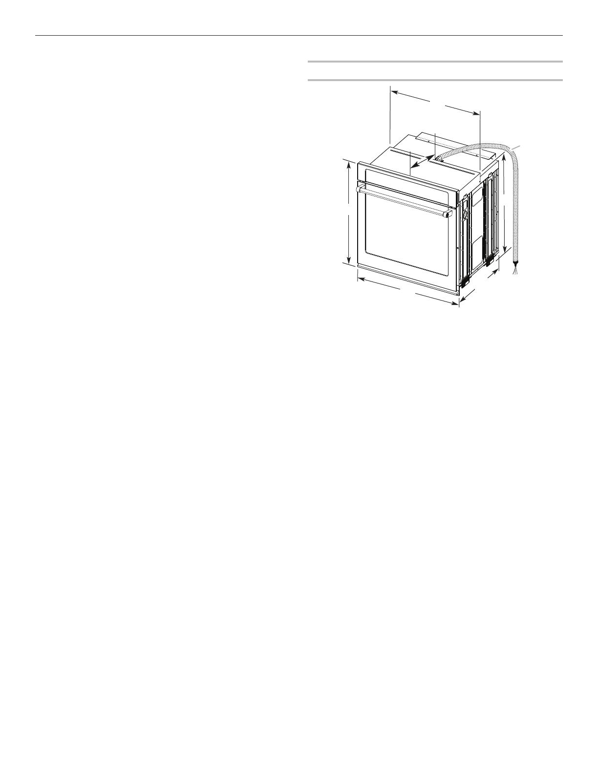
Dimensions du produit – Fours simples
B
C
D
E
A
G
F
Modèles de 30 po (76,2 cm)
A. Hauteur totale maximum : 28
3
/
4
po (72,8 cm)
B. Largeur maximum de l’encastrement:
28
1
2
po (72,4cm)
C. Hauteur d’encastrement : 26
3
/
4
po (67,9 cm)
D. Profondeur maximum de l’encastrement :
23
1
/
4
po (59,1 cm)
E. Largeur totale: 30po (76,2cm)
F. De l’arrière du tableau de commande jusqu’à
l’extrémité avant du serre-câbles:
12po (30,5cm)
G. Longueur du conduit exible: 48po (121,9cm)
19
Dimensions de l’armoire – Fours simples
Four simple sous le plan de travail
(sans table de cuisson au-dessus)
Fours simples installés dans une armoire
* REMARQUE: Pour les fours simples, la hauteur de la
découpe peut être comprise entre 26
15
/
16
po et 29
7
/
16
po
(68,4cm et 74,8cm).
A
B
C
D
E
Modèles de 30 po (76,2 cm)
A. Largeur minimum de l’armoire:
30po (76,2cm)
B. Du dessus de la découpe au
dessous du plan de travail:
minimum de 1
1
/
2
po (3,8cm)
C. Du fond de la découpe au
plancher : 5
1
/
4
po (13,3 cm)
D. Largeur de la découpe:
28
1
/
2
po (72,4cm)
E. Hauteur minimum de la
découpe: 28po (71,2cm)
F
E
B
C
A
D
G
Modèles de 30 po (76,2 cm)
A. Largeur minimum de l’armoire :
30 po (76,2 cm)
B. Du sommet de la découpe au bas de
la porte de l’armoire supérieur:
1po (2,5cm)
C. Du fond de la découpe au plancher:
32po (81,3cm)
D. Largeur de la découpe:
28
1
/
2
po (72,4cm)
E. Du fond de la découpe au dessus de
la porte de l’armoire:
minimum de 1
1
/
2
po (3,8cm)
F. Hauteur recommandée de la
découpe: 28po (71,2cm)*
G. Profondeur de découpe:
24po (60,7cm)
20
Dimensions du produit – Fours doubles Dimensions de l’armoire – Fours doubles
Fours doubles installés dans une armoire
* REMARQUE: Pour les fours doubles, la hauteur de la
découpe peut être comprise entre 48
7
/
8
po et 52
3
/
16
po
(124,1cm et 132,6cm).
C
A
E
D
B
F
G
Modèles de 30 po (76,2 cm)
A. Hauteur totale maximum :
51
3
/
16
po (130,0 cm)
B. Largeur maximum de l’encastrement :
28
1
2
po (72,4cm)
C. Hauteur d’encastrement :
48
13
/
16
po (124,0 cm)
D. Profondeur maximum de
l’encastrement : 23
1
/
4
po (59,1 cm)
E. Largeur totale : 30 po (76,2 cm)
F. De l’arrière du tableau de commande
jusqu’à l’extrémité avant du serre-
câble : 12 po (30,5 cm)
G. Longueur du conduit exible:
66po (167,6cm)
F
E
A
D
G
B
C
Modèles de 30 po (76,2 cm)
A. Largeur minimum de l’armoire :
30 po (76,2 cm)
B. Du sommet de la découpe au bas de
la porte de l’armoire supérieur:
1po (2,5cm)
C. Du fond de la découpe au plancher :
14
3
/
4
po (37,5 cm) recommandé.
Du fond de la découpe au plancher :
4po à 14
3
/
4
po (10,2 cm à 37,5 cm)
acceptable.
D. Largeur de la découpe:
28
1
/
2
po (72,4cm)
E. Du fond de la découpe au dessus de
la porte de l’armoire:
minimum de 1
1
/
2
po (3,8cm)
F. Hauteur recommandée de la
découpe : 50
1
/
4
po (127,6 cm)*
G. Profondeur de découpe:
24po (60,7cm)
  • Page 1 1
  • Page 2 2
  • Page 3 3
  • Page 4 4
  • Page 5 5
  • Page 6 6
  • Page 7 7
  • Page 8 8
  • Page 9 9
  • Page 10 10
  • Page 11 11
  • Page 12 12
  • Page 13 13
  • Page 14 14
  • Page 15 15
  • Page 16 16
  • Page 17 17
  • Page 18 18
  • Page 19 19
  • Page 20 20
  • Page 21 21
  • Page 22 22
  • Page 23 23
  • Page 24 24
  • Page 25 25
  • Page 26 26
  • Page 27 27
  • Page 28 28
  • Page 29 29
  • Page 30 30
  • Page 31 31
  • Page 32 32

KitchenAid KODE900HBS Installation guide

Type
Installation guide
This manual is also suitable for

Ask a question and I''ll find the answer in the document

Finding information in a document is now easier with AI

in other languages