Page is loading ...

Sl2000D v1.0 Rev. B EN.doc 12/5/2005
1
S
L
2
000D
Electronic Code Lock
Features
FeaturesFeatures
Features
! Door Relay output
! Status transistor output
! Aux transistor output
! Door Contact input
! Exit Button input
! INSTALLER code for programming
! MASTER code for arming/disarming
! USER codes for door opening
! Door Alarm indication
! Option: Timed Lock-out after three wrong codes
! Option: Access only when Disarmed
! Programmable length of codes
! User indexing for easy administration of codes
! Nonvolatile memory
! Keypad with backlight
! Door Bell key
! Three LEDs and buzzer
! Tamper contacts
Introduction
IntroductionIntroduction
Introduction
The SL2000D electronic code lock is designed for operation as a
stand-alone door access control unit. The device is equipped with
one relay output, two transistor outputs and two NO inputs. All codes
and parameters configuring the device’s operation are stored in
nonvolatile memory. The device is dedicated for indoor use only.
Functional Description
Functional DescriptionFunctional Description
Functional Description
Note: The C1,C2…C10 parameters which appear in this manual
refer to configuration settings programmed to the SL2000 during
Memory Reset procedure (see section: Configuring the SL2000 later
in this document).
Door R
Door RDoor R
Door Relay
elay elay
elay O
OO
Output
utpututput
utput
This output is designed to control a door locking device (e.g. door
strike or magnetic lock). Each time the valid USER code is entered
the SL2000 starts counting time delay specified by C1C2
parameters and after it elapses the relay output is activated for a
time defined by C3C4 value. The triggering of the Door Relay output
is indicated by LED OPEN (orange), this LED lights as long as Door
Relay output is on.
Note: If the option Disable Access in Armed Mode is enabled the
activation of the Door Relay output may occur only when the unit
operates in the Disarmed mode.
Status
Status Status
Status O
OO
Output
utpututput
utput
When the SL2000 is in Armed mode this output is not active and
remains in high resistance condition. When code lock switches to
Disarmed mode the Status output shorts to supply minus (GND) and
stay in this condition as long as the SL2000 operates in the
Disarmed mode. The maximum current sink by this output is
internally limited to 1.0A, the maximum voltage applied to it must not
exceed 16V DC. The Status output can be used for rearming of an
alarm zone or to control any other device or system which requires
on/off method of control.
Note: The arming and disarming of a code lock can be carried out by
MASTER code only.
Aux
AuxAux
Aux
O
OO
Output
utpututput
utput
Normally this output remains in high resistance state, if triggered it
shorts to supply minus (GND). The Aux output has been designed to
indicate two situations:
! Door Bell event
! Door Alarm event
Whenever the Bell key is pressed for a moment or the [#] key is
pressed and held down longer then half a second, the Aux output
goes steady on (shorts to supply minus), the Aux output remains in
this condition as long as the Bell or [#] key is being pressed.
The Aux output can be also activated when Door Alarm is active.
The code lock indicates the Door Alarm through pulsed modulation
of the Aux output. Thanks to this feature (steady or pulsed output)
operator may distinguish the Bell signal from the Door Alarm.
The maximum current sink by this output is internally limited to 1.0A,
the maximum voltage applied to it must not exceed 16V DC.
Normally the Aux output is used to trigger some kind of warning
device (e.g. alarm siren or buzzer).
Note: The Door Alarm has higher priority then the Door Bell event.
As a result when two of those events occur simultaneously only the
Door Alarm is indicated on the output line.
Exit Button I
Exit Button IExit Button I
Exit Button Input
nputnput
nput
Triggering of this input activates Door Relay output on the same
rules as the entry of a valid USER code. The Exit Button is a NO
type – it becomes triggered when shorted to supply minus (GND).
Door Contact I
Door Contact IDoor Contact I
Door Contact Input
nputnput
nput
This input is dedicated for a connection of a door open sensor.
When input is open or left unconnected the code lock assumes that
door is closed, when input is shorted to supply minus (GND) the
SL2000 assumes that door is open.
Note: If you are not going to use a door open sensor leave the Door
Contact input unconnected. Without a door open sensor the SL2000
will not indicate the Door Alarm.
Door
Door Door
Door Alarm
AlarmAlarm
Alarm
The Door Alarm will occur when:
! door has been opened without entering of a valid USER
code
! door has been opened without pressing of the Exit Button
! door has not been closed within C5C6 time from the
moment when door locking device was deactivated

Sl2000D v1.0 Rev. B EN.doc 12/5/2005
2
The Door Alarm is indicated by pulsed activation of the Aux output
which is accompanied by a continues acoustic signal generated by
the internal buzzer. Pressing any key will cease the acoustic signal –
however this does not cancel the alarm indication on Aux output
.
The indication on the Aux output disappears when door becomes
closed or automatically after 60 seconds from the moment when
alarm arose.
Option 1: Timed Lock
Option 1: Timed LockOption 1: Timed Lock
Option 1: Timed Lock-
--
-out
out out
out
If this option is enabled the lock disables the keypad for 60 seconds
after three attempts of entry of incorrect code. After this time the
SL2000 re-enables the keypad and is ready to accept new keypad’s
entries. The end of 60 seconds lock-out time is indicated by two
series of two beeps (** **).
Option 2:
Option 2: Option 2:
Option 2: Disable Access in Armed mode
Disable Access in Armed modeDisable Access in Armed mode
Disable Access in Armed mode
If this option is enabled the SL2000 grants access to a room only
when it operates in Disarmed mode. With this option active the
access to the controlled door will be disabled for both all USER
codes and Exit Button unless the SL2000 will be switched to
Disarmed mode.
Note: Thanks to this option the MASTER user can disable access to
the room by switching the unit to Armed mode and vice verso, he
can enable access to controlled door by switching the code lock to
Disarmed mode. The SL2000 can be switched between Armed and
Disarmed modes through the MASTER code only.
Arming and Disarming of the
Arming and Disarming of the Arming and Disarming of the
Arming and Disarming of the Code
Code Code
Code Lock
LockLock
Lock
In normal operation mode the SL2000 may work either in the Armed
or Disarmed mode. The Armed mode is signalled by LED ARMED
(red) whereas the Disarmed mode is signalled by LED DISARMED
(green). The actual operating mode of a lock is also indicated on the
Status output line which when active indicates that unit is Disarmed.
The switching between Armed and Disarmed modes can be carried
out by MASTER code only. Whenever code lock switches to
Disarmed mode is generates two series of two beeps (** **) whereas
when switches to Armed mode it generates two beeps (**) only.
C
CC
Codes
odesodes
odes
The SL2000 offers three types of codes:
! MASTER Code
! INSTALLER Code
! USER Codes
Each type of code is designed for individual purpose. The length of
each code can be programmed during Memory Reset procedure.
The entry of each code must be followed by the [#] key which is
used to mark the end of a code.
MASTER Code
The MASTER code is used to switch the SL2000 between Armed
and Disarmed modes, it can be 4-10 digits long.
INSTALLER Code
The INSTALLER code is required to enter the Installer Programming
mode, it can be 4-10 digits long.
USER Codes
These codes are used for activation of the Door Relay output. Each
time a valid USER code is entered the SL2000 starts counting C1C2
time delay and then when it passes by the unit activates Door Relay
output. The Door Relay output is activated for time defined by C3C4
settings. The USER codes can be 2-8 digits long.
Note: The SL2000 enables programming of maximum 55 USER
codes, each of them can open the door.
C
CC
Commands
ommandsommands
ommands
Commands can be entered during normal working time of a SL2000
code lock and doesn’t require entry to the programming mode.
[USER Code] [#]
Whenever a valid USER code is entered the code lock generates
two beeps (**) and then starts count C1C2 time delay. After it passes
by the SL2000 activates Door Relay output for time defined by C3C4
settings. During this time door locking device is energized and user
can open the door.
[MASTER Code] [#]
Each time the MASTER code is entered the SL2000 changes its
arming mode (switches from Armed to Disarmed mode or in reverse
direction).
[INSTALLER Code] [#]
After this command code lock generates two beeps (**) and enters
the Installer Programming mode. In this mode installer can program
the USER codes to a unit.
[*] [Old INSTALLER Code] [#] [New INSTALLER Code] [#]
This command erases the old INSTALLER code and program new
INSTALLER code. If command is successfully accomplished the unit
generates three series of two beeps (** ** **).
[*] [Old MASTER Code [#][New MASTER Code] [#]
This command erases the old MASTER code and program new
MASTER code. If command is successfully accomplished the unit
generates three series of two beeps (** ** **).
Note: Whenever you re-program MASTER or INSTALLER code
remember that new code programmed into a unit must have the
same length as the old one.
[Bell Key]
A single short press of this key activates the Aux output and internal
buzzer for a time of ~2…3 seconds. The indication on Aux output
and buzzer is continued for entire time as long as Bell key is being
pressed.
[#]
Normally it marks the end of a code but when pressed separately for
a time longer the 0.5s it acts in the same way as Bell key.
Programming of
Programming of Programming of
Programming of the
the the
the USER
USERUSER
USER
C
CC
Codes
odesodes
odes
The SL2000 enables programming of up to 55 different USER
codes. The USER codes can be managed (added/deleted/changed)
only in the Installer Programming mode.
In order to program the
USER codes you must first enter the Installer Programming mode
and the you have access to the programming commands listed
below:
[0] [1] [#] [code] [# ]
Programming of the USER code no. 1
[0] [2] [#] [code] [#]
Programming of the USER code no. 2
..
..
..
[5] [5] [#] [code] [#]
Programming of the USER code no. 55
[0] [0] [#]
Deletes all USER codes.

Sl2000D v1.0 Rev. B EN.doc 12/5/2005
3
[9] [9] [#] [code] [#]
Deletes the code entered in square brackets.
[#]
Exit from the Installer Programming mode.
When the code lock accepts the new USER code it generates two
series of two beeps (** **). Any attempt to program a USER code
which already exists in memory or to program it with a code length
bigger then programmed during Memory Reset will cause the
programming error signalled by the long acoustic beep.
Configuring the SL2000
Configuring the SL2000 Configuring the SL2000
Configuring the SL2000 -
--
- Memory Reset
Memory Reset Memory Reset
Memory Reset
In order to configure the SL2000 you must perform the Memory
Reset and then enter sequentially 10 digits (called C1-C10) which
will configure the unit for individual installation. After the Memory
Reset the entire contents of the code lock memory is erased
(including all codes) and initialized with Default (Factory) settings.
In order to perform Memory Rest do the following:
! Turn off the power supply
! Place a jumper on RESET contacts
! Turn on the power supply
! Wait till the moment when device will sound three series of
two beeps (** ** **)
! Remove the jumper from the RESET contacts
! Enter sequentially ten digits C1-C10
! After the last digit is entered the code lock generates the
three series of two beeps (** ** **) then ends the Memory Reset
procedure and switches to normal working mode.
C1C2 : Open Delay, specifies the time delay from a moment when
access is granted to a moment when Door Relay will be activated. It
can be programmed from 00 to 99s.
C3C4 : Lock Activation Time, specifies the time for which Door
Relay will be activated when access is granted. It can be
programmed from 00 to 99s.
C5C6 : Time for Door Closing, specifies the time within which door
must be closed. It can be programmed from 00 to 99s, the
00 value sets unlimited time for closing.
C7: Enables or disables of reprogramming of the MASTER
and INSTALLER codes, enter 0-3.
Value
Reprogramming of the
MASTER code
Reprogramming of the
INSTALLER code
0 Enabled Enabled
1 Disabled Enabled
2 Enabled Disabled
3 Disabled Disabled
Note: If reprogramming of a given code is disabled the SL2000
allows you a single attempt only to program of the given code. Once
the code is programmed, you will not be able to change it unless the
Memory Reset is carried out. Use this function to disable the end
user to change your MASTER and INSTALLER code.
C8: Enabling and disabling Option1 and Option 2, enter 0-3.
Value Option 1 Option 2
0 Disabled Disabled
1 Enabled Disabled
2 Disabled Enabled
3 Enabled Enabled
C9: Defines the length of the USER codes, enter 0-3.
0 : USER codes are 2 digits long
1 : USER codes are 4 digits long
2 : USER codes are 6 digits long
3 : USER codes are 8 digits long
C10: Defines the length of the MASTER and INSTALLER
codes, enter 0-3.
0 : Both codes are 4 digits long
1 : Both codes are 6 digits long
2 : Both codes are 8 digits long
3 : Both codes are 10 digits long
If an illegal operation occur during Memory Rest the device will
signal an error (long beep) and will return to the beginning of the
programming so you can start to enter the C1-C10 digits once again.
The Memory Reset procedure automatically comes to an end when
the last (C10) digit is entered. The device stores the configuration as
well as all codes in a nonvolatile memory which can be
reprogrammed whenever required. After the Memory Reset
procedure comes to an end all codes are set to default values (see
section Default Codes).
Example:
The following digits C1-C10 were entered during the Memory Reset
procedure: [0][1][0][2][3][3][1][0][2][3]
This sequence sets the following options:
! Open Delay: 01 second
! Lock Activation Time: 02 seconds
! Time for Door Closing: 33 seconds
! Reprogramming of the MASTER code: disabled
! Reprogramming of the INSTALLER code: enabled
! Option 1; Timed Lock-out : option off
! Option 2; Disable Access in Armed Mode: option off
! USER codes: 6 digits
! MASTER and INSTALLER codes: 10 digits
Default Codes
After the Memory Reset is accomplished the following codes are
automatically programmed into a unit:
MASTER Code
All digits are “1” (1111…), the length of the code depends on the
C10 parameter entered during Memory Reset procedure.
INSTALLER Code
All digits are “2” (2222…), the length of the code depends on the
C10 parameter entered during Memory Reset procedure.

Sl2000D v1.0 Rev. B EN.doc 12/5/2005
4
USER Code no 01
All digits are “3” (3333…), the length of the code depends on the C9
parameter entered during Memory Reset procedure.
USER Code 02..55
All USER codes no 02 -55 are blank (they doesn’t exist).
Installing the C
Installing the CInstalling the C
Installing the Code Lock
ode Lockode Lock
ode Lock
! The SL2000 code lock should be mounted near the
supervised door on a vertical piece of supporting structure.
! Assure that the surface beneath of the controller’s rear
panel is flat and smooth.
! Disconnect power supply before making any electrical
connections.
! Once installed and electrically connected, the unit has to
be properly programmed.
! When forgotten, MASTER and INSTALLER codes can be
reprogrammed through Memory Reset procedure.
! The code lock must be supplied form reliable power
supply, calculate the adequate wire gauge to guarantee that the
voltage dropout between the power supply and the DC input of
SL2000 will not exceed 1V in the worst case.
! It is recommended to supply door release device (e.g.
door strike or magnet lock) and SL2000 from separate power
supply but when both code lock and door release device are
supplied from the same power source you must use separate
pairs of cable for each of them.
! Always add the silicon diode (e.g. 1N400x series) in
parallel to door release device – locate diode as close as possible
to door release and as far as possible from the code lock.
! It is forbidden to supply the door release device directly
from the DC input terminals of a code lock.
! Do not attempt to use Door Relay output for switching of a
voltages higher then 28V DC/AC.
Technical
Technical Technical
Technical S
SS
Specification
pecificationpecification
pecification
P
ARAMETER
V
ALUE
DC Supply 10...16 VDC
Current Consumption
Avg. 25 mA @ 12V DC,
Max. 80 mA @ 16V DC with relay
output active
Anti-sabotage Protection
(Tamper)
NC contact, 50mA/24V
Environmental Class
(according to EN 50131-1)
Class I, Indoor
Temp.: +5°C +40°C
Relative humidity: 10 - 95% (non-
condensing)
Dimensions
45 X 151.5 X 20.5
Weight ~ 90g
Approvals CE
Connection Terminal
Connection TerminalConnection Terminal
Connection Terminals
ss
s Assignments
Assignments Assignments
Assignments
C
ONNECTION
T
ERMINAL
D
ESCRIPTION
12V Supply plus
GND Supply minus
BIST.
Status transistor output, max. current sink
1.0A/16V DC
BELL
Aux transistor output, max. current sink
1.0mA/16V DC
TAMP
TAMP
Tamper contacts, NC max. 50mA/24V
DR Exit Button input, NO type
DC Door Contact input, NO type
COMM
Door Relay output, COMMON contact,
1.5A/24V DC/AC
NO/NC
Door Relay output, NO or NC contact,
1.5A/24V DC/AC
(selection through jumper)

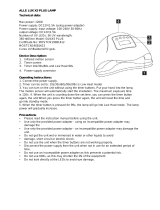
230VA
+ACC-
Reserve battery
12 V
Power Supply
(e.g. PS10/PS20)
Mains transformer
+12V
BIST
TAMP
DC
NO
GND
BELL
DR
COM
Warning device
or Door Bell
SL 2000
Door Contact
(NO type)
Tamper loop
Arming/disarming of the alarm system or another on/off type control
Exit Button
(NO type)
Door lock
Cdr144
Typical wiring of SL2000 code lock
Door Alarm and
Door Bell output
Supply

151,5
134,5
45
22
20,5
1
3
5
7
9
*
2
4
6
8
0
#
Without Reset
(normal position)
Normally Open (NO) contacts
Normally Close (NC) contacts
JP2
Memory Reset
JP1
Selection of the Relay Contacts
Memory Reset
12V BIST TAMP
Connection Terminals Assignements
DC NO/NC
GND BELL DR COM
Armed mode Disarmed mode Door Open
Amber LED
(orange)
Gree LEDn
Red LED
Optical Inicators
(LEDs)
1 1
2 2
3
Openning
Closing
Openning and closing methods of SL2000D coversOpenning
and
closing
methods
of
SL2000D
covers
SL2000D Views and Installation Diagram
Cdr143
JP1
JP2
12V
DR
DC
COMM
NO/NC
GND
BIST
BELL
TAMP
:
: Exit Button
: Door Contact
: Door Relay
Supply plus
input, NO
input, NO
, COMMON contact
:
: Status
: Tamper
Supply minus
transistor output, 1A sink
contacts
: AUX transistor output, 1A sink
: Door Relay, NO or NC contact
/