
S50
SCISSORS LIFT FOR VEHICLES
ELEKTROHYDRAULISCHE
SCHERENHEBEBÜHNE FÜR
FAHRZEUGE
PONTE SOLLEVATORE A FORBICE PER
VEICOLI
PONT ÉLÉVATEUR A CISEAUX POUR
VÉHICULES
ELEVADOR DE TIJERAS PARA
VEHÍCULOS
Rotary Lift Rev.2 18/04/2015
ROTARY 1-45,115-116,46-57,59-112,113-114,2
O
p
e
r
a
t
i
o
n
&
m
a
i
n
t
e
n
a
n
c
e
E/15


1
Manuale di istruzioni per l’uso e la manutenzione del
Instructions and maintenance manual for
Manuel d’instructions pour l’utilisation et l’entretien du:
Bedienungs- und Wartungsanleitung für
Manual de instrucciones para uso y mantenimiento de los
SOLLEVATORE PER AUTOVETTURE
SCISSORS VEHICLES LIFT
ELÉVATEURS POUR AUTOMOBILES
ELEKTROHYDRAULISCHE SCHERENHEBEBÜHNE
ELEVADOR PARA AUTOMÓVILES
Modello - Model - Modell - Modèle - Modelos
S50
COSTRUTTORE: - MANUFACTURER: - HERSTELLER: - CONSTRUCTEUR: - FABRICANTE:
BlitzRotary GmbH
Hüfinger Straße 55
78199 Bräunlingen
1
a Emissione - 20/04/2015 - 1st Edition - 20/04/2015
1
a Édition - 20/04/2015 - 1. Ausgabe - 20/04/2015 - 1ª Edición – 20/04/2015
CENTRO DI ASSISTENZA AUTORIZZATO:
AUTHORISED SERVICE CENTRE:
SERVICE APRÈS-VENTE AGRÉÉ:
KUNDENDIENSTCENTER
CENTRO DE ASISTENCIA AUTORIZADO:
Rev.2 ................................18/05/2015

Indice
Imballaggio, trasporto e stoccaggio Pag.03
Introduzione Pag.05
1 Descrizione della macchina Pag.07
2 Specifiche tecniche Pag.09
3 Sicurezza Pag.14
4 Installazione Pag.24
5 Funzionamento ed uso Pag.40
6 Controlli periodici Pag.44
7 Inconvenienti e rimedi Pag.61
Appendice A Informazioni particolari Pag.66
Appendice B Parti di ricambio Pag.68
Dichiarazioni di conformità
Table des matières
Emballage, transport et stockage Page 04
Introduction Page 06
1 Description de L’appareil Page 08
2 Caractéristiques techniques Page 10
3 Sécurité Page 14
4 Installation Page 25
5 Fonctionnement Page 41
6 Contrôle périodique Page 45
7 Pannes et remèdes Page 62
Annexe A Informations particulieres Page 67
Annexe B Pièces de Rechange Page 69
Déclaration de Conformité
Inhaltsverzeichnis
Verpackung, Transport und Lagerung Seite 04
Einleitung Seite 06
1 Beschreibung der Hebebühne Seite 08
2 Technische Spezifikationen Seite 10
3 Sicherheit Seite 14
4 Installation Seite 24
5 Betrieb und Gedauch Seite 41
6 Regelmässige Kontrollen Seite 45
7 Störungen und Abhilfen Seite 62
Anhang A Besondere Informationen Seite 67
Anhang B Ersatzteilliste Seite 69
Konformitätserklärung
Contents
Packing, transport and storage Page 03
Introductio Page 05
1 Description of the machine Page 07
2 Technical specifications Page 09
3 Safety Page 14
4 Installation Page 24
5 Operation Page 40
6 Regular checks Page 44
7 Troubleshooting Page 61
Appendix A Special Info Page 66
Appendix B Spare parts Page 68
Declarations of Conformity
Indice
Embalaje, transporte y almacenaje Pág. 04
Introducción Pág. 06
1 - Descripción de la máquina Pág. 08
2 - Características técnicas Pág. 10
3 - Seguridad Pág. 14
4 - Instalación Pág. 25
5 - Funcionamiento Pág. 41
6 -Verificaciones periódicas Pág. 45
7 - Detección de fallas y remedio Pág. 63
Apéndice A -Informaciónes particulares Pág. 67
Apéndice B- Piezas de Recambio Pág. 69
Declaratión de Conformidad
2
ATTENZIONE
Il presente libretto istruzione è redatto nella lingua del costrutto
-
re e in altre lingue comunitarie. In caso di contestazione, inciden
-
te, o quant’altro, ai fini giuridici fa testo esclusivamente la versio
-
ne in lingua italiana. Il costruttore declina ogni e qualsiasi re
-
sponsabilità per danni diretti e/o indiretti cagionati da cattiva tra
-
duzione o errata interpretazione del testo tradotto.
ATTENTION
This instruction manual is drawn up in the language of the manu
-
facturer and in other European languages. If there is a dispute,
accident or anything else, the Italian language version of this ma
-
nual will be exclusively used for legal purposes. The manufactu
-
red declines all and any responsibility for direct or indirect dama
-
ge caused by poor translation or erroneous interpretation of the
translated text.
ATTENTION
Ce manuel est écrit dans la langue du fabricant et dans d’autres
langues communautaires. En cas de litige, d’un accident, ou que
ce soit, à des fins juridiques est la version texte uniquement en
italien. Le fabricant décline toute responsabilité pour tous dom-
mages directs et / ou indirects causés par traduction ou une in-
terprétation erronée du texte traduit.
ACHTUNG
Das vorliegende Handbuch wurde in der Muttersprache des Her
-
stellers und in weiteren Sprachen der Europäischen verfasst. Im
Falle von Beanstandungen, Unfällen usw. ist zu juristischen
Zwecken ausschließlich die Version in italienischer Sprache
maßgeblich. Der Hersteller lehnt jegliche Haftung für direkte
und/oder indirekte Schäden ab, die durch schlechte Übersetzung
oder falsche Auslegung des übersetzten Textes entstehen.
ATENCIÓN
Este manual está escrito en el lenguaje del fabricante y en otras
lenguas comunitarias. En caso de conflicto, accidente, o lo que
sea, para los efectos legales es la versión de sólo texto en italia
-
no. El fabricante se exime de cualquier responsabilidad por los
daños directos y / o indirectos causados por error de traducción
o interpretación errónea del texto traducido.

Fig.1 Abb.1
N 2410 Kg
AK 2510 Kg
LT 2710 Kg
AKLT 2810 Kg
IMBALLAGGIO, TRASPORTO E STOCCAGGIO
LE OPERAZIONI DI IMBALLAGGIO, SOLLEVAMENTO,
MOVIMENTAZIONE, TRASPORTO E DISIMBALLO DEVONO
ESSERE AFFIDATE ESCLUSIVAMENTE A PERSONALE CHE SIA
ESPERTO IN TALI OPERAZIONI
IMBALLAGGIO
Il sollevatore nelle versioni standard, viene spedito già montato con i
seguenti pezzi:
N°2 basi e pedane (P1 - P2) chiuse una sull’altra (1 Fig. 1);
N°1 centralina di comando (2 Fig. 1);
N°1 serie di fermaruote (per sollevatore installato incassato) (3 Fig. 1);
N°1 serie di rampe di salita/discesa ( per sollevatore installato a
pavimento) (4 Fig. 1).
TRASPORTO
L’ imballo può essere sollevato o spostato sia con carrelli elevatori che
con gru o carri ponte. L’eventuale imbracatura deve essere
accompagnata da una seconda persona al fine di evitare pericolose
oscillazioni del carico.Rispettare, infine, al momento dello scarico o del
carico della merce i propri punti di presa e i carichi come indicato in
figura.
I
ATTENZIONE
All’arrivo, verificare che la merce non abbia subito danni durante il
trasporto e che ci siano tutti i pezzi indicati nella lista di spedizione.
Comunicare immediatamente all’ incaricato o al trasportatore le
eventuali mancanze o irregolarità e eventuali danni che il sollevatore
abbia subito durante il trasporto.2
PACKING, TRANSPORT AND STORAGE
ALL PACKING, LIFTING, HANDLING, TRANSPORT AND
UNPACKING OPERATIONS ARE TO BE PERFORMED
EXCLUSIVELY BY EXPERT PERSONNEL
PACKING
Standard versions of the lift are dispatched previously assembled and
equipped as follows:
No.2 bases and platforms (P1-P2), one closed onto the opther (1 Fig.
1);
No.1 control box (2 Fig. 1);
No.1 set of wheel-stops (for recessed version) (3 Fig. 1);
No.1 set of on/off ramps (for models installed on flor) (4 Fig. 1).
TRANSPORT
Packing can be lifted or moved by lift trucks, cranes or bridge cranes. In
case of slinging, a second person must always take care of the load, in
order to avoid dangerous oscillations. Furthermore, during loading and
unloading operations goods must be handled as shown in the picture.
I
WARNING
At the arrival of the goods, check for possible damage due to transport
operations. Also verify that all items specified in the delivery notes are
included. In case of missing parts, possible defects or damages due to
transport, the person in charge or the carrier must be immediately
informed.
3
1
2
(70 kg)
3
(80 kg)
4
(180 kg)

EMBALLAGE, TRANSPORT ET STOCKAGE
LES OPERATIONS D’EMBALLAGE, DE SOULEVEMENT, DE
DEPLACEMENT, DE TRANSPORT ET DE DEBALLAGE DOIVENT
ETRE EXCLUSIVEMENT CONFIEES A UN PERSONNEL
COMPETANT DANS CE TYPE D’OPERATIONS.
EMBALLAGE)
En version standard, l’élévateur est expédié pré-assemblé et se
compose des éléments suivants:
2 plates-formes élévatrices assemblées (P1-P2) refermées et posées
l’une sur l’autre (1 Fig. 1);
1 pupitre de commande (2 Fig. 1);
1 jeu de butées de roues (pour les ponts encastrés) (3 Fig. 1);
1 jeu de rampes d’accès (pour les ponts posés au sol) (4 Fig. 1).
TRANSPORT
Le pont emballé peut être soulevé et déplacé soit avec un chariot
élévateur, soit à l’aide d’une grue ou d’un pont roulant.
Lorsque le pont est suspendu par des élingues, il est indispensable qu’il
soit accompagné par une seconde personne afin d’éviter que ne se
produise un balancement dangereux de la charge.
Lors des opérations de chargement ou de déchargement, il est
impératif de respecter les points de prise indiqués dans la figure
ci-dessous.
I
ATTENTION
A l’arrivée, contrôler que la marchandise n’ait subi aucune détérioration
au cours du transport et que tous les éléments indiqués sur le
bordereau de colisage soient effectivement présents. Communiquer
immédiatement au transporteur tout manquant ou tout dommage
constaté sur l’élévateur.
VERPACKUNG, TRANSPORT UND LAGERUNG
ALLE VERPACKUNGS-, HEBE-, TRANSPORT UND
AUSPACKARBEITEN SIND NUR VON
AUSGEBILDETEMFACHPERSONAL, DAS KENNTNISSE DES LIFTS
UND DER BEDIENUNGSANWEISUNG BESITZT,
DURCHZUFÜHREN.
VERPACKUNG
Die Hebebühne in Standard-Ausführung wird bereits zusammengebaut
mit folgenden Teilen geliefert:
Nr. 2 Grundrahmen und Plattformen ( P1 - P2 ), aufeinander
geschlossen (1 Abb. 1);
Nr. 1 Steuerzentrale (2 Abb. 1);
Nr.1 Radsperren (für Einbau-Hebebühnen) (3 Abb. 1);
Nr.1 Serie Auf- und Abfahrtrampen (für auf dem Boden installierte
Hebebühnen) (4 Abb. 1).
TRANSPORT
Die Verpackung kann mit Hilfe eines Gabelstaplers oder mit einem
Kran oder Laufkran gehoben und bewegt werden.
Beim Heben mit Gurtzeug muss immer eine zweite Person anwesend
sein, die aufzupassen hat, dass die gehobene Last nicht ins Schwingen
gerät.
Beim Abladen oder Aufladen der Ware ist darauf zu achten, dass die
Hubmittel an den auf der Abbildung dargestellten Hubpunkten angelegt
werden.
I
ATTENTION
Bei der Ankunft der Maschine ist zu kontrollieren, dass diese keine
Transportschäden aufweist und dass alle in den Versandunterlagen
aufgeführten Teile vorhanden sind. Wenn Teile fehlen sollten oder
wenn Transportschäden festgestellt werden, ist der Beauftragte oder
der Spediteur umgehend diesbezüglich zu unterrichten.
EMBALAJE, TRANSPORTE Y ALMACENAJE
LAS OPERACIONES DE EMBALAJE, TRANSPORTE, DESIMBALAJE
DEBEN SER EFECTUADAS POR PERSONAL QUE TENGA
EXPERIENCIA EN DICHAS OPERACIONES Y QUE CONOZCA BIEN
EL ELEVADOR Y ESTE MANUAL.
EMBALAJE
El elevador en la versión standard, se suministra con los siguientes
componentes:
N° 2 bases y plataformas (P1 y P2) cerradas una sobre la otra (1 Fig.
1);
N° 1 centralita de mandos (2 Fig. 1);
N° 1 juego de para-ruedas en caso de elevador empotrado (3 Fig. 1);
N° 1 juego de rampas de subida/descenso (en caso de que no se
quiera empotrar el elevador) (4 Fig. 1).
TRANSPORTE
El embalaje puede ser elevado y trasladado con camión de plataforma,
camión de grúa ó grúa de puente.
En caso de tirar con una estinga, una segunda persona debe cuidar
siempre de la carga, para evitar oscilaciones peligrosas. Además,
durante la carga y la descarga, el género debe manejarse como
muestra la figura.
I
ATENCIÓN
A la llegada del género, verifique los posibles daños producidos
durante el transporte. También verifique que todos los artículos
especificados en las notas de entrega estén incluidos. En caso de
pérdidas, posibles defectos o daños debidos al transporte, debe
informarse inmediatamente de ello al transportista, haciéndolo constar
en la nota de entrega.
4

Fig.2 Abb2
INTRODUZIONE
I
ATTENZIONE
Questo manuale è stato scritto per il personale di officina addetto all’uso del sollevatore
(operatore) e per il tecnico addetto alla manutenzione ordinaria (manutentore), prima di
effettuare qualsiasi operazione sul sollevatore e/o sul suo imballaggio, leggere tutto il
manuale, poichè esso contiene informazioni importanti per:
·
LA SICUREZZA DELLE PERSONE addette all’uso ed alla
manutenzione ordinaria,
·
LA SICUREZZA DEL SOLLEVATORE,
·
LA SICUREZZA DEI VEICOLI sollevati.
CONSERVAZIONE DEL MANUALE
Il manuale è parte integrante del sollevatore e deve sempre accompagnarlo,
anche in caso di vendita. Conservare il manuale col sollevatore, in luogo
facilmente accessibile. L’operatore ed il manutentore devono poterlo consultare in
qualsiasi momento.
SI RACCOMANDA, IN PARTICOLARE, UNA LETTURA ATTENTA E RIPETUTA
DEL CAPITOLO 3, CHE CONTIENE IMPORTANTI INFORMAZIONI E AVVISI
RELATIVI ALLA SICUREZZA.
Il sollevatore è stato progettato e costruito rispettando quanto segue:
Direttive Europee 2004/108/CE - 2006/42/CE - 2006/95/CE
NORME TECNICHE :
Norme Europee
EN 1493-2010 / EN ISO 121002010
IMPIANTO ELETTRICO: EN 60204-1
Il sollevamento, il trasporto, il disimballo, il montaggio, l’installazione e la messa in
servizio, la taratura e le registrazioni iniziali, la manutenzione STRAORDINARIA,
la riparazione, la revisione, lo spostamento e lo smantellamento del sollevatore
devono essere eseguiti dai tecnici specializzati dei RIVENDITORI AUTORIZZATI o dei
CENTRI ASSISTENZA AUTORIZZATI dal Costruttore (vedere centro assistenza autorizzato
indicato nel frontespizio).
l costruttore non risponde di alcun danno a persone, veicoli od oggetti causati
dagli interventi sopracitati se effettuati da personale non autorizzato o da un uso
improprio o non consentito del sollevatore.
Per comprendere il linguaggio adottato nel presente manuale, l’operatore deve
possedere esperienza specifica nelle attività di officina, di assistenza,
manutenzione e riparazione dei veicoli nonchè la capacità di interpretare
correttamente i disegni e le descrizioni riportate nel manuale e la conoscenza
delle norme antinfortunistiche generali e specifiche vigenti nel paese in cui viene
installato il sollevatore.
Gli stessi criteri valgono per la scelta del tecnico manutentore che dovrà, inoltre,
possedere le conoscenze tecniche specifiche e specialistiche (meccaniche,
elettriche) necessarie per effettuare in sicurezza gli interventi previsti nel manuale.
Il significato di “operatore” e “manutentore” è il seguente
OPERATORE: persona addetta all’uso del sollevatore.
MANUTENTORE: persona addetta alla manutenzione ordinaria del sollevatore.
INTRODUCTION
I
WARNING
This manual has been prepared for workshop personnel expert in the use of the
lift (operator) and technicians responsible for routine maintenance (maintenance
fitter); read the manual before carrying out any operation with the lift and/or the
packing. This manual contains important information regarding:
·
THE PERSONAL SAFETY of operators and mainte nance
workers,
·
LIFT SAFETY,
·
HE SAFETY OF LIFTED VEHICLES
CONSERVING THE MANUAL
The manual is an integral part of the lift , which it should always accompany ,
even if the unit is sold. The manual must be kept in the vicinity of the lift, in an
easily accessible place. The operator and maintenance staff must be able to
locate and consult the manual quickly and at any time.
ATTENTIVE AND REPEATED READING OF CHAPTER 3, WHICH CONTAINS
IMPORTANT INFORMATION AND SAFETY WARNINGS, IS PARTICULARLY
RECOMMENDED.
Lift rack has been designed and built in compliance with the following:
European directives 2004/108/CE - 2006/42/CE - 2006/95/CE
TECHNICAL STANDARDS
European standards
EN 1493-2010 / EN ISO 121002010
ELECTRIC PLANT EN 60204-1
The lifting, transport, unpacking, assembly, installation, starting up, initial
adjustment and testing, EXTRAORDINARY maintenance, repair, overhauls, transport and
dismantling of the lift must be performed by specialised personnel from the LICENSED
DEALER or an SERVICE CENTRE authorised by the manufacturer (see authorised dealer on
frontispiece).
The manufacturer declines all responsibility for injury to persons or damage to
vehicles or objects when any of the above mentioned operations has been
performed by unauthorised personnel or when the rack has been subject to
improper use.
In order to understand the terminology used in this manual, the operator must
have specific experience in workshop, service, maintenance and repair activities,
the ability to interpret correctly the drawings and descriptions contained in the
manual and be acquainted with the general and specific safety rules relevant to
the country in which the machine has been installed.
The same applies to the maintenance fitter, who must also possess specific and
specialised knowledge (mechanical, engineering) needed to perform the
operations described in the manual in complete safety.
The words “operator” and “maintenance fitter” used in this manual are construed
as follows:
OPERATOR: person authorised to use the lift.
MAINTENANCE FITTER: person authorised for routine maintenance of the lift.
5

INTRODUCTION
I
ATTENTION
Ce manuel a été rédigé pour le personnel d’atelier affecté à l’utilisation du pont élévateur (opérateur) et
au technicien chargé de la maintenance ordinaire (agent d’entretien). Avant d’effectuer quelque
opération que ce soit sur l’élévateur et/ou sur l’emballage, il est impératif de lire attentivement
l’ensemble de ce manuel car celui-ci contient des informations importantes pour:
·
LA SECURITE DES PERSONNES chargées de l’utilisation et de
la maintenance ordinaire;
·
LA SECURITE DE L’ELEVATEUR;
·
LA SECURITE DES VEHICULES soulevés.
CONSERVATION DU MANUEL
Ce manuel fait intégralement partie de l’élévateur et doit toujours l’accompagner, même en cas de
revente.
Il doit toujours être conservé à proximité de l’élévateur, en un endroit facilement
accessible. L’opérateur et l’agent d’entretien devront pouvoir s’y référer et le consulter
rapidement à tout moment.
IL EST EN PARTICULIER RECOMMANDE DE PROCEDER A UNE LECTURE
ATTENTIVE ET REPETEE DU CHAPITRE 3 QUI CONTIENT DES INFORMATIONS
IMPORTANTES ET DES CONSIGNES RELATIVES A LA SECURITE.
L’élévateur a été conçu et construit en conformité avec les réglementations suivantes:
DIRECTIVES EUROPÉENNES 2004/108/CE - 2006/42/CE - 2006/95/CE
NORMES TECHNIQUES
Norme européenne
EN 1493-2010 / EN ISO 12100/1 2005 - EN ISO 12100/2 2005
ÉQUIPEMENT ÉLECTRIQUE EN 60204-1
Le soulèvement, le transport, le déballage, le montage, l’installation et la mise en
service, le tarage ou les réglages initiaux, l’entretien EXTRAORDINAIRE, la réparation, la
révision, le déplacement et la destruction de l’élévateur doivent être effectués par les techniciens
spécialisés des REVENDEURS AUTORISES et des CENTRES DE SERVICE APRES-VENTE
AGREES par le Constructeur (voir en première page l’adresse du service après-vente agréé). Le
constructeur dégage toute responsabilité vis à vis des dommages qui pourraient être causés aux
personnes, aux véhicules ou autres objets lors des interventions citées ci-dessus si celles-ci ont été
effectuées par un personnel non autorisé, ou lors d’une utilisation de l’élévateur incorrecte ou non
prévue par le constructeur.
Pour comprendre le langage adopté dans le présent manuel, l’opérateur doit posséder
une expérience spécifique dans le domaine du travail en atelier, du service après
vente, del’entretien et de la réparation automobile, ainsi que la capacité d’interpréter
correctement les dessins et les descriptions figurant dans ce manuel et la
connaissance des normes générales relatives à la protection contre les accidents du
travail en vigueur dans le pays où l’élévateur est installé.
Les mêmes critères sont à prendre en compte pour le choix de l’agent d’entretien qui
devra, en plus, posséder les connaissances spécifiques et techniques (mécaniques,
électriques) nécessaires pour effectuer en toute sécurité les interventions prévues dans
ce manuel.
Dans les textes de ce manuel, vous trouverez souvent les termes “opérateur” et “agent
d’entretien” dont la signification est la suivante:
OPERATEUR : personne affectée à l’utilisation de l’élévateur,
AGENT D’ENTRETIEN: personne chargée de l’entretien ordinaire de l’élévateur.
EINLEITUNG
I
ACHTUNG
Dieses Handbuch wurde für das mit der Bedienung der Hebebühne beauftragte Werkstattpersonal
(Bediener) und für den mit der ordentlichenWartung beauftragten Techniker (Wartungsfachmann)
verfasst. Daher ist vor j dem Eingriff an der Hebebühne und/oder an dem Verpackungsmateri
andbuch zu lesen, denn es enthält wichtige Informationen für:
·
Die Sicherheit der mit der dem Gebrauch und der orden tlichen
Wartung beauftragten Personen;
·
Die Sicherheit der Hebebühne;
·
Die Sicherheit des zu hebenden Fahrzeuges.
AUFBEWAHRUNG DES HANDBUCHES
Das Handbuch stellt ein Teil der Hebebühne dar und muss diese immer begleiten, auch wenn
sie verkauft wird Das Handbuch muss immer an einem leicht zugängliche Ort in der Nähe der
Hebebühne aufbewahrt werden. Der Bediener und die mit derWartung beauftragte Person
müssen das Handbuch jederzeit zur Verfügung haben.
INSBESONDERE WIRD EMPFOHLEN, DAS KAPITEL 3 MEHRMALS
AUFMERKSAM ZU LESEN, DENN DIESES KAPITEL ENTHÄLT WICHTIGE
INFORMATIONEN UND HINWEISE BEZÜGLICH DER SICHERHEIT.
Die Hebebühnen werden unter Beachtung der folgenden Vorschriften entwickelt
und hergestellt:
EUROPÄISCHE RICHTLINIEN 2004/108/CE - 2006/42/CE - 2006/95/CE
TECHNISCHER STANDARD
Europäischer Standard
EN 1493-2010 / EN ISO 12100/1 2005 - EN ISO 12100/2 2005
ELEKTRIK EN 60204-1
Heben, Transport, Auspacken, Montage, Installation und Inbetriebnahme, Eichung und
Einstellungen, AUSSERORDENTLICHE Wartung, Reparatur, Inspektion, Verschiebung und
Abbruch der Hebebühne müssen durch Fachtechniker der vom Hersteller AUTORISIERTEN
VERTRAGSHÄNDLER oder (siehe auf der Titelseite angegebenes autorisiertes Kundendienstcenter)
durchgeführt werden: Der Hersteller haftet nicht für Personen-und/oder Sachschäden, die auf die oben
beschriebenen Eingriffe zurückgeführt werden können, wenn diese Eingriffe durch nicht autorisiertes
Personal durchgeführt wurden, oder wenn die Schäden auf einen unsachgemäßen oder unzulässigen
Gebrauch der Hebebühne zurückzuführen sind.
Zum Verstehen der in diesem Handbuch angewandten Fac sprache muss der
Bediener über spezifischeWerkstatterfahrungen bezüglich Pannendienst sowie
Wartung und Reparatur von Fahrzeugen verfügen, und muss in der Lage sein, die in
diesem Handbuch enthaltenenZeichnungen und Beschreibungen zu verstehen. Ferner
muss der Bediener die im jeweiligen Aufstellland der Hebebühne geltenden
allgemeinen und spezifischen Unfallverhütungsvorschriften kennen. Die gleichen
Kriterien gelten für dieWahl desWartungstechnikers, der ferner über die spezifischen
technischen und Fachkenntnisse (Mechanik, Elektrik) verfügen muss, die zur
Ausführung der im Handbuch beschriebenen Arbeitsgänge unter sicheren
Bedingungen erforderlich sind.
Im Handbuch werden häufig die Begriffe “Bediener” und “Wartungsfachmann”
verwendet.
Diese Begriffe haben folgende Bedeutung.
BEDIENER: Für den Betrieb der Hebebühne zuständige Person.
WARTUNGSFACHMANN: Für die ordentlicheWartung der Hebebühne zuständige
Person.
INTRODUCCIÓN
I
ATENCIÓN
Este manual ha sido escrito para el personal de taller que se ocupa del uso del elevador
(operario) y para el técnico que se ocupa del mantenimiento ordinario (servicio) por tanto, antes
de realizar cualquier operación en el elevador y/o en su embalaje, es preciso leer atentamente
todo el manual, ya que contiene informaciones importantes para:
·
LA SEGURIDAD DE LAS PERSONAS que se ocupan del uso y
del mantenimiento ordinarios;
·
LA SEGURIDAD DEL ELEVADOR;
·
LA SEGURIDAD DE LOS VEHÍCULOS elevados.
CONSERVACIÓN DEL MANUAL
El manual es parte integrante del elevador y debe acompañarlo siempre, aun en caso de
venta. Deberá estar cerca del elevador, en lugar fácilmente accesible. El operario y el personal
de servicio lo deberá hallar rápidamente para consultar en cualquier momento.
SE RECOMIENDA, PARTICULARMENTE, UNA LECTURA ATENTA Y
REPETIDA DEL CAPÍTULO 3, QUE CONTIENE IMPORTANTES
INFORMACIONES Y AVISOS RELATIVOS A LA SEGURIDAD.
Los elevadores han sido proyectados y fabricados respectando las siguientes
DIRECTIVAS EUROPEAS 2004/108/CE - 2006/42/CE - 2006/95/CE
NORMAS TÉCNICAS
Normas europeas
EN 1493-2010 / EN ISO 12100/1 2005 - EN ISO 12100/2 2005
EQUIPO ELÉCTRICO: EN 60204-1
La elevación, el transporte, el desembalaje, el montaje, la instalación y puesta en
funcionamiento, la verificación y los ajustes iniciales, el mantenimiento
EXTRAORDINARIO, la reparación, la revisión, la manipulación y el desmantelamiento del elevador
deben ser ejecutados por los técnicos especializados del REVENDEDOR AUTORIZADO o por los
CENTROS DE ASISTENCIA AUTORIZADOS del Fabricante (ver centro de asistencia autorizado
indicado al principio).
El fabricante no responde de daños a personas, vehículos u objetos causados por las
intervenciones antes citadas si se han efectuado por personal no autorizado o por un
uso impropio o no consentido del elevador.
Para comprender el lenguaje usado en este manual, el operario debe tener experiencia
específica en las actividades de taller, de asistencia, mantenimiento y reparación de
vehículos así como la capacidad de interpretar correctamente los dibujos y
descripciones indicades en el manual y el conocimiento de las normas preventivas
generales y específicas vigentes en el país donde se instala el elevador.
Idénticos criterios son válidos para la elección del técnico de mantenimiento que
deberá, además, poseer los conocimientos específicos y de especialización
(mecánico, eléctrico) necesarios para realizar con seguridad las intervenciones
previstas en el manual.
En el texto del manual se encontrará a menudo las frases “operario” y “personal de
servicio” cuyos significados son los siguientes:
OPERARIO: persona que se ocupa del uso del elevador.
PERSONAL DE SERVICIO: persona que se ocupa del mantenimiento ordinario
del elevador.
6

Fig.3 Abb3
CAP.1. DESCRIZIONE DELLA MACCHINA
Il ponte sollevatore a forbice è adatto a sollevare tutti i tipi di autovetture
e furgoni con peso non superiore a 5000 Kg. Può essere fornito di
torrette con prolunghe integrate.Il sollevatore a forbice soddisfa tutte le
esigenze di: autoriparatori, gommisti, carrozzieri e operatori del settore.
I vari tipi di sollevatore sono riportati in figura 2. Il ponte sollevatore può
essere fornito sia a pavimento che ad incasso, ed è stato progettato per
il sollevamento e lo stazionamento in quota di autoveicoli e furgoni.
CARATTERISTICHE SOLLEVATORE
Autolivellamento alla massima altezza;
sincronismo idraulico-volumetrico delle pedane e delle torrette;
dispositivo di controllo di dislivello delle pedane;
dispositivo di sicurezza meccanica a cremagliera;
centralina idraulica con pompa a ingranaggi;.
dispositivo acustico di segnalazione discesa torrette
dispositivo acustico di segnalazione e pulsante di autorizzazione per
l’ultimo tratto di discesa pedana (sia per sollevatore che per torretta);
circuito idraulico dotato di sicurezza contro la rottura dei tubi e l’eccesso
del carico;
comando centralina a mezzo scheda elettro-meccanica;
comandi a bassa tensione (24 v);
guide laterali per traverse idrauliche.
Il sollevatore è composto da:
GRUPPO STRUTTURA FISSA;
GRUPPO STRUTTURA DI SOLLEVAMENTO;
CENTRALINA DI COMANDO.
GRUPPO STRUTTURA FISSA
E’ costituita dalla base del ponte sollevatore, costruita in una struttura in
lamiera di acciaio sagomato con fori per il fissaggio al suolo (1 Fig. 3).
GRUPPO DI SOLLEVAMENTO
E’ costituito da leve in acciaio sagomato (2-3 Fig. 3)
La pedana portante è costituita da longheroni portanti in tubolare di
acciaio, collegati tra loro con montanti ancorati ai bracci con perni di
acciaio nei punti fissi e con pattini nei punti mobili.Tutti i perni sono
muniti di boccole autolubrificanti esenti da manutenzione (4-5 Fig. 3).
CENTRALINA DI COMANDO
E’ formata da un box contenente nella parte inferiore il serbatoio olio
idraulico e il gruppo pompa-motore. Nella parte superiore sono
alloggiati i comandi ed il quadro elettrico.
CHAP. 1 DESCRIPTION OF THE MACHINE
Scissor lift is able to lift any kind of car and van whose weight is not
higher than 5000 Kg. On request it can be equipped with auxiliary lift
having integrated extension to lift cars with a longer wheelbase. Our
scissor lift can meet any demand coming from car repairmen, tyre
dealers, body repairmen and from all those who work in this field.
Scissor lift is fixed, that is anchored to the ground. It can be supplied in
both platform or recessed version and it has been designed and built for
car and van lifting and placing operations.
LIFT SPECIFICATIONS
Self-levelling to the maximum height
hydraulic-volumetric synchronisation of the platforms and lift table;
device that controls difference in platform levels;
mechanical rack safety device;
hydraulic control box with gear pump;
acoustic device that sounds when the lift table lowers; Acoustic device
and authorisation button for last lowering section of platform (both for lift
last lowering section of platform (both for lift and for lift table);
hydraulic circuit with safety system against hose breakage and excess
load;
control box control by means of electro-mechanical board;
low voltage controls (24V);
side guides for hydraulic cross members.
Our car lift iis equipped as follows:
BASE (fixed structure);
ARMS, PLATFORM (lifting and unfixed structure);
CONTROL BOX.
FIXED STRUCTURE UNIT
It consists of the car lift base, which is madeof profiled steel sheet with
clamping holes (1 Fig. 3).
LIFTING STRUCTURE UNIT
It is composed by the arms made of steel (2-3 Fig. 3).
The load-carrying platform is made of tubolar steel pieces linked to
each other by vertical rods anchored to the arms by steel pins at the
fixed points and by pads at the moveable ones. All lifting system links
are equipped with self-lubricating bushings where manutenance is not
required (4-5 Fig. 3).
CONTROL BOX
It is a metal box containing, at the bottom, the hydraulic oil tank and the
motor-pump set, and on top, all the controls.
7
1
5
3
4
2

CHAP. 1 DESCRIPTION DE L’APPAREIL
Ce pont élévateur à ciseaux a été conçu pour soulever tous types de
voitures et de fourgons dont le poids n’excède pas 5000 kg. Il peut être
fourni avec un dispositif de levage auxiliaire équipé de rallonges
intégrées qui permet de soulever tous les véhicules, même rallongés.
Cet élévateur à ciseaux répond aux besoins des réparateurs
automobiles, des marchands de pneumatiques, des carrossiers et
autres opérateurs du secteur automobile. L’élévateur est fixe, c’est à
dire fixé au sol. Il peut être fourni en version posé au sol ou en version
encastré. Il a été conçu pour le soulèvement et le stationnement en
hauteur de voitures automobiles et de fourgons.
CARACTÉRISTIQUES ÉLÉVATEUR
Nivelage automatique à le maximum de hauteur;
synchronisme hydraulique-volumétrique des plates-formes et des
tourelles;
dispositif de contrôle de la dénivellation des plates-formes;
dispositif de sécurité mécanique à crémaillère;
groupe hydraulique avec pompe à engrenages;
dispositif sonore de signal descente tourelle, dispositif sonore de signal
et bouton dispositif 6. sonore de signal et bouton d’autorisation pour la
partie finale de la descente plate-forme (pour élévateur et tourelle);
circuit hydraulique à sécurité contre la rupture des tuyaux et l’excès de
charge;
commande groupe avec carte électromécanique;
commandes à basse tension (24V);
guides latéraux pour traverses hydrauliques.
L ‘élévateur se compose des parties suivantes:
EMBASES (groupe structure fixe);
BRAS DE CISEAUX, PLATES-FORMES (groupe structure mobile de
soulèvement);
CENTRALE DE COMMANDE.
GROUPE STRUCTURE FIXE
Il se compose des embases du pont élévateur, construites en tôle
d’acier façonnée et pourvues de trous pour la fixation au sol (1 Fig. 3).
GROUPE STRUCTURE MOBILE DE SOULEVEMENT
Il est constitué par des bras de ciseaux d’acier (2-3 Fig. 3).
Deux plates-formes portantes. Celles-ci sont composées de longerons
en tubes d’acier raccordés entre eux par des montants reliés aux bras
par l’intermédiaire d’axes en acier aux points fixes et de galets aux
points mobiles. Toutes les articulations de l’élévateur sont munies de
bagues autolubrifiantes ne nécessitant aucun entretien (4-5 Fig. 3).
CENTRALE DE COMMANDE
Elle se compose d’un pupitre métallique à la partie inférieure duquel est
placé le réservoir d’huile et le groupe moto-pompe hydraulique. Les
commandes sont logées dans la partie supérieure.
KAP. 1 BESCHREIBUNG DER HEBEBÜHNE
Die Scherenhebebühne ist zu Heben aller Personenkraftwagen und
Lieferwagen mit einem Gewicht von maximal 5000 kg geeignet. Die
Hebebühne ist mit Hilfsplattformen mit eingebauten Verlängerungen
ausgerüstet, damit auch die Personenkraftwagen gehoben werden
können, die einen höheren Achstand haben. Die Scherenhebebühne
erfüllt die Ansprüche der Reparaturwerkstätten, Reifenhändler,
Karosseriemechaniker, usw. Die Hebebühne ist feststehen, d.h. sie ist
am Boden verankert. Die Hebebühne kann sowohl in der Ausführung
zum Verankern am Boden als zum Einbau geliefert werden, und wurde
zum Heben von Personenkraftwagen und Lieferwagen auf eine
bestimmte Höhe entwickelt und gebaut.
EIGENSCHAFTEN
Selbstgleichschaltung die Höhe off max;
hydraulisch-mechanischer Synchronbetrieb der Plattformen und
Nebenplattformen;
kontrollvorrichtung zum Erkennen einer unterschiedlichen
Plattformausrichtung;
mechanische Sicherheitsvorrichtung mit Zahnstange;
hydrauliksteuergerät mit Zahnradpumpe;
Akustische Warnvorrichtung für das Absenken der Nebenplattformen
Akustische Warnvorrichtung und Genehmigungstaste für den letzten
Teil der Plattformabsenkung (für Hebebühne und Nebenplattform);
hydraulikkreislauf mit Sicherheitsvorrichtung gegen Beschädigung der
Leitungen und Überlast;
elektromechanische Steuerungsplatine;
niederspannungssteuerung (24 V);
seitliche Führungen für Hydraulikquerträger.
Die Hebebühne besteht aus:
GRUNDRAHMEN (feste Struktur);
HEBEL, PLATTFORM (Bewegliche Hebestruktur):
STEUERZENTRALE.
FESTSTEHENDE STRUKTUR
Bestehend aus dem Grundrahmen, hergestellt aus geschweißtem
Stahlblech mit Befestigungsöffnungen zur Aufnahme der
Befestigungsdübel für die Verankerung am Boden (1 Abb. 3).
BEWEGLICHE HEBESTRUKTUR
Besteht aus Hebeln aus Stahl (2-3 Fig. 3).
Die tragende Plattform besteht aus Stahlrohr-Längsträgern, die mittels
Ständern miteinander verbunden sind, die ihrerseits mit Stahlzapfen an
den feststehenden Punkten und mitWalzen an den beweglichen
Punkten an die Arme angeschlossen sind. Alle Gelenke des
Hebesystems sind mit wartungsfreien selbstschmierenden Buchsen
ausgerüstet (4-5 Abb. 3).
STEUERZENTRALE
Besteht aus einem Metallkasten, in dessen Unterteil der
Hydrauliköltank und das Pumpen-Motor-Aggregat untergebracht ist. Im
Oberteil sind die Steuerungen untergebracht.
CAP. 1 DESCRIPCION DE LA MAQUINA
El elevador de tijeras es apto para levantar todos los tipo de vehículos
con peso de hasta 5000 kg. Se suministra con plataformas auxiliares
con extensiones integradas que permiten alzar todos los vehículos de
larga distancia entre ejes. Este elevador puede satisfacer las
necesidades de: mecánicos, neumatiqueros, reparadores de
carrocerías y operadores del sector. El elevador es fijo, o sea clavado
al suelo. Puede ser suministrado tanto para empotrar como para ser
colocado en el piso.
CARACTERÍSTICAS DEL ELEVADOR
Autonivelación a el máximo de altura;
sincronismo hidráulico-volumétrico de las plataformas y de las torretas;
dispositivo de control de desnivel de las plataformas;
dispositivo de seguridad mecánica de cremallera;
centralita hidráulica con bomba de engranajes;
dispositivo acústico de señalización descenso torreta dispositivo
acústico de señalización y pulsador de autorización para el último
tramo de descenso plataforma (tanto para elevador como para torreta);
circuito hidráulico dotado de seguridad contra la rotura de los tubos y el
exceso de carga;
mando centralita con placa electromecánica;
mandos de baja tensión (24 v);
guías laterales para travesaños hidráulicos.
El elevador está compuesto por
BASE (estructura fija);
BRAZOS, PLATAFORMAS (estructura móvil y de elevación);
CENTRAL DE MANDOS.
ESTRUCTURA FIJA
Consta de la base del elevador, una estructura de chapa de acero
perfilado con agujeros de sujeción al suelo (1 Fig. 3).
ESTRUCTURA MOVIL Y DE ALZAMIENTO
Consta de brazos de acero (2-3 Fig. 3).
La plataforma de soporte está formada por piezas de acero tubular
conectados entre ellos a través de barras verticales ancladas a los
brazos con pasadores de acero en los puntos fijos y con rodillos en los
puntos móviles.Todas las articulaciones del sistema de elevación están
equipadas con casquillos autolubricantes que no requieren
mantenimiento (4-5 Fig. 3).
CENTRAL DE MANDOS
Consta de una caja metálica que contiene en la parte inferior el
depósito de aceite hidráulico y el grupo bomba-motor. En la parte
superior están ubicados los botones de mando.
8

9
Fig. 4 Abb4
CAP.2 SPECIFICHE TECNICHE
DATI TECNICI:
Funzionamento .........................................elettro-idraulico
Portata.......................................................5000 Kg
Portata torrette ..........................................3500 Kg
Tempo di salita pedane.............................55 sec
Tempo di discesa pedane .........................40 sec
Tempo di salita torrette..............................20 sec
Tempo di discesa torrette..........................20 sec
Alimentazione pneumatica ........................4 / 8 bar
Peso totale ................................................ 2410 / 2810 Kg
Temperatura di funzionamento .................-10°C / +40°C
Rumorosità................................................ < 76 db
Ambiente di lavoro: locale chiuso.
Potenza motore.........................................3 Kw
Tensione....................................................230-400 V trif. +/- 5%
Frequenza .................................................50 Hz
N° poli........................................................2
Velocità .....................................................1400 giri/1’
Forma costruttiva.......................................B14
Classe isolamento.....................................F
Assorbimento: ...........................................230V / 13A
..................................................................400V / 7,5A
Il collegamento del motore deve essere eseguito riferendosi agli schemi
elettrici allegati. Il senso di rotazione del motore è sinistro (antiorario)
come indicato nella targhetta applicata sul motore stesso.
CENTRALINA IDRAULICA:
Cilindrata ...................................................4,2 cm3/g
Valvola di max. tarata a.............................310 bar
OLIO:
Il serbatoio dell’olio contiene olio idraulico a base minerale secondo normativa
ISO/DIN 6743/4 con grado di contaminazione non superiore alla classe 18/15 se
-
condo normativa ISO 4406 come IP HYDRO OIL 32; SHELL TELLUS T 37 o
equivalenti.
CHAPTER 2SPECIFICATIONS
TECHNICAL DATA:
Operation...................................................electro-hydraulic
Carrying Capacity......................................5000 kg
Auxiliary lif capacity...................................3500 kg
Platforms lift time.......................................55 sec.
Platforms lowering time.............................40 sec.
Lift tables lift time ......................................20 .....sec.
Lift tables lowering time.............................20 .....sec.
Pneumatic feed .........................................4 / 8 bar
Noisy level.................................................2410 / 2810 Kg
Working temperature.................................-10°C / +40°C
Weight ....................................................... < 76 db
Installation requirements: enclosed area.
Power motor..............................................3 Kw
Voltage ......................................................230-400V th.-ph +/-5%
Frequency .................................................50 Hz
Poles .........................................................2
Speed........................................................1400 rpm
Building shape...........................................B14
Isulation class............................................F
Absorption .................................................230V / 13A
..................................................................400V / 7,5 A
When connecting the motor refer to the enclosed wiring diagrams. The
motor has left-handed rotation (counter-clockwise) as shown on the
data plate on the casing.
POWER UNIT:
Dispacement .............................................4,2 cm3/g
Relief valve................................................310 bar
OIL:
The hydraulic oil tank is filled with mineral oil to ISO/DIN
6743/4,contamination category no higher tahn class 18/15 according to
ISO 4406, such as IP HYDRO OIL 32; SHELL TELLUS T 37 or an
equivalent oil.
Construction tolerance ± 0.5 cm
Pay attention to hole levelling

CHAP. 2 CARACTERISTIQUES
TECHNIQUES
FICHE TECHNIQUE
Fonctionnement.........................................éléctro-hydraulique
Portée........................................................5000 kg
Portée levage auxiliaire.............................3500 kg
Temps de montée plate-formes ................55 secondes
Temps de descente plate-formes..............40 secondes
Temps de montée table auxiliaire .............20 secondes
Temps de descente table auxiliaire...........20 secondes
Alimentation pneumatique.........................4/8 bar
Poids total .................................................2410 / 2810 Kg
Température de fonctionnement ...............-10°C / +40°C
Niveau sonore ........................................... < 76 db
Environnement de travail : local fermé.
Puissance..................................................3 kW
Tension......................................................230-400 V tri. +/- 5%
Fréquence .................................................50 Hz
Nb de pôles ...............................................2
Vitesse de rotation ....................................1400 tr/mn
Forme constructive....................................B14
Classe d’isolement ....................................F
Intensité absorbée.....................................230V / 13 A
..................................................................400V / 7,5 A
Les branchements du moteur doivent être réalisés en se référant aux
schémas électriques contenus dans la présente notice. Le sens de
rotation du moteur est à gauche (anti-horaire) comme indiqué par la
flèche apposée sur le moteur même.
POMPE:
Cylindrée ...................................................4,2 cm3 / tr.
Soupape de surpression tarée à ...............310 bar
HUILE:
Le réservoir contient de l’huile hydraulique à base minérale conforme à
la norme ISO/DIN 6743/4 avec un degré de contamination non
supérieur à la classe 18/15 selon la norme ISO 4406, telle que les
huiles IP HYDRO OIL 32, SHELL TELLUS T 37 ou équivalent.
KAPITEL 2 TECHNISCHE DATEN
TECHNISCHE DATEN:
Arbeitsweise..............................................elektro- hydraulisch
Tragfähigkeit..............................................5000 kg
Tragfähigkeit Radfreiheber........................3500 kg
Hubzeit Plattformen...................................55 Sek
Absenkzeit Plattformen .............................40 Sek
Hubzeit Abhub...........................................20 Sek
Absenkzeit Abhub .....................................20 Sek
Druckluftversorgung ..................................4/8 bar
Gesamtgewicht der Hebebühne................2410 / 2810 Kg
Umgebungstemperatur..............................-10°C / +40°C
Geräuschpegel.......................................... < 76 db
Einsatzumgebung: Geschlossener Raum.
Elektromotor Leistung ...............................3 kW
Spannung..................................................230-400V 3PH +/-5%
Frequenz ...................................................50 Hz
Polanzahl ..................................................2
Drehzahl....................................................1400 UpM
Bauform.....................................................B14
Isolationsklasse.........................................F
Strom Verbrauch .......................................230V / 12,8 A
..................................................................400V / 7,5 A
Beim Anschluss des Motors sind die beigestellten Schaltpläne zu
beachten. Der Motor ist linksdrehend (gegen den Uhrzeigersinn), wie
auch auf dem Motorschild angegeben ist.
PUMPE:
Hubraum....................................................4,2 cm3/g
Höchstgeschwindigkeit geeicht auf ...........310 bar
Öl:
Der Öltank enthält hydraulisches Öl auf Mineralbasis gemäß der Norm
ISO/DIN 6743/4 mit einem Verunreinigungsgrad nicht höher als Klasse
18/15, gemäß der ISO-Norm 4406, wie zum Beispiel IP Hydro Öl
32,Shell Tellus T 37 oder ähnliches.
CAPITULO 2– CARACTERISTICAS TECNICAS
Datos técnicos:
Funcionamiento.........................................electro-hidráulico
Capacidad .................................................5000 kg
Capacidad elevador auxiliar......................3500 kg
Tiempo de subida plataformas..................55 segundos
Tiempo de descenso plataformas ............40 segundos
Tiempo de subida mesa auxiliaire.............20 segundos
Tiempo de descenso mesa auxiliaire ........20 segundos
Alimentacion neumática ............................4/8 bares
Peso total .................................................2410 / 2810 Kg
Temperatura de funcionamiento ...............-10°C / +40°C
Ruido......................................................... < 76 db
Lugar de trabajo: local cerrado.
Potencia: ...................................................3 Kw
Tensión:........................................230-400V trifásico-monofásico +/-5%
Frecuencia:................................................50 Hz
N° de polos:...............................................2
Velocidad: .................................................1400 rpm
Forma:.......................................................B14
Clase de aislamiento:................................F
Absorción: .................................................230V / 13A
..................................................................400V / 7,5A
El motor debe conectarse haciendo referencia a los esquemas
eléctricos. El sentido de rotación del motor es izquierdo, o sea levógiro,
según indicado en la placa del motor.
BOMBA:
Cilindrada: .................................................4,2 cm³/g
Válvula de alivio: .......................................310 bares
ACEITE:
El depósito contiene aceite hidráulico de base mineral según las
normas ISO/DIN6743/4 con nivel de contaminación no superior a la
clase 18/15 según las normas ISO 4406, tal como IP HYDRO OIL 32,
SHELL TELLUS T 37 o equivalentes.
10
Construction tolerance ± 0.5 cm
Pay attention to hole levelling

SCHEMA D’ENCASTREMENT POUR ELEVATEUR
Pour l’installation de l’élévateur, il est nécessaire de réaliser les
travaux de génie civil décrits sur la figure ci-après, en respectant les
caractéristiques suivantes:
beton armè avec RBK min 25 N/mm²;
plans d’appui bien nivelés;
parallélisme entre les fosses.
Lors de la réalisation des travaux de génie civil, prévoir aussi:
un fourreau pour le passage des tuyauteries de la centrale de
commande à l’élévateur (utiliser un tuyau de PVC de Ø intérieur 150
mm minimum)..
SCHEMA DELLE FONDAMENTA PER PONTE
SOLLEVATORE
Per l’installazione del sollevatore occorre realizzare apposite
fondazioni, come illustrate nelle figure seguenti, aventi le seguenti
caratteristiche:
calcestruzzo con RBK min 25 N/mm²;
piani di appoggio livellati;
parallelismo tra le buche.
Per tolleranza di costruzione vedere disegni. Come da disegno
prevedere:
un canale per il passaggio dei tubi dalla centralina al sollevatore
(utilizzare tubo in PVC con Ø int. minimo di 150 mm.).
FUNDAMENT FÜR DIE HEBEBÜHNE
Für die Installation der Hebebühne muss ein geeignetes Fundament
(siehe Abbildung) angefertigt werden, das folgende Eigenschaften
besitzen muss:
beton mit RBK min 25 N/mm²;
nivellierte Auflageebene;
parallelität zwischen den Öffnungen.
Zusätzlich zu diesem Fundament ist zu realisieren:
ein Kanal für die von der Steuerzentrale zur Hebebühne führenden
Schläuche (ein PVC-Schlauch mit Innendurchmesser von mind. 150
mm verwenden);
INSTALLATION SCHEME FOR SCISSORS LIFT
To install the lift it is necessary to execute suitable foundations (see
figure) with the following characteristics:
concrete with RBK min 25 N/mm²;
levelled bearing surfaces;
perfect parallelism between holes.
At the same time, it is necessary to provide what follows:
a passage channel for pipes from control box to lift (use a PVC pipe
with inner diameter not less than 150 mm).
ESQUEMA DE CIMIENTOS DEL ELEVADOR
Para instalar el elevador hace falta realizar los cimientos según
indicado en la figura, teniendo las siguientes características:
hormigón con RBK min 25 N/mm²;
superficie de soporte bien niveladas;
paralelismo perfecto entre los huecos.
Hace falta prever asimismo lo siguiente:
un canal para el pasaje de los tubos de la central de mandos al
elevador (usar tubode PVC con diámetro interior mínimo de 150 mm).
11
Rain water drain well
Construction tolerance ± 0.5 cm
Pay attention to hole levelling

FONDAMENTA STANDARD SX FOUNDATIONS FOR STANDARD LEFT
GENIE CIVIL POUR STANDARD SX FUNDAMENT STANDARD LINKS
CIMIENTOS STANDARD IZQ
Fig.5 Abb.5
FONDAMENTA OPTIONAL DX FOUNDATIONS FOR OPTIONAL RIGHT
GENIE CIVIL POUR OPTION DX FUNDAMENT OPTIONAL RECHTS
CIMENTOS OPCIONAL DER
Fig.6 Abb6
12

Fig.7 - Abb. 7
DIMENSIONS ET TYPES DE VEHICULES SOULEVABLES
Les ascenseurs sont adaptés pour lever tous les types de voitures et
véhicules commerciaux d’un poids ne dépassant pas 5000 kg
I
ATTENTION
LA CHARGE DOIT ÊTRE RÉPARTIE COMME EN Fig. 6 et 7.
Les schémas de répartition de la charge se référer aux pires conditions
d’utilisation.
Fig.6 Répartition des poids “ Plates-formes capacité 5000 Kg
Fig.7 Répartition des poids “ Levage auxiliaire capacité 3500 Kg
TIPI DI VEICOLI SOLLEVABILI E INGOMBRI
I sollevatori sono adatti al sollevamento di tutti i tipi di autoveicoli e
veicoli commerciali di peso non superiore a 5000 Kg.
I
ATTENZIONE
IL CARICO DEVE ESSERE RIPARTITO COME IN Fig. 6 e 7.
Gli schemi di ripartizione del carico si riferiscono alle peggiori condizioni
di utilizzo.
Fig. 6 Ripartizione pesi “Pedane da 5000 Kg”
Fig.7 Ripartizione pesi “Torrette da 3500 Kg”
MIT DER HEBEBÜHNE KÖNNEN FOLGENDEN FAHRZEUGE GE
-
HOBEN WERDEN - ABMESSUNGEN
Die Hebebühne sind für das Heben alle Arten von Pkw und
Nutzfahrzeugen Gewicht von nicht mehr als 5000 kg.
I
ACHTUNG
DIE LAST MUSS DIVIDED WIE IN Abb. 6 unt 7.
Die Diagramme der Lastverteilung beziehen sich auf den schlimmsten
Bedingungen für die Verwendung.
Abb.6 Gewichtverteilung “Plattformen 5000 Kg Tragkraft
Abb.7 Gewichtverteilung “Radfreiheber 3500 Kg Tragkraft
TYPES OF VEHICLES SUITABLE FOR BEING LIFTED AND
OVERALL DIMENSIONS
Lifts are suitable for lifting all types of cars and commercial vehicles of
weight not greater than 5000 Kg.
I
WARNING
THE LOAD MUST BE DIVIDED AS IN Fig. 6 and 7.
The diagrams of load distribution refer to the worst conditions of use.
Fig.6 Weight distribution “Lifting platforms with 5000 Kg capacity”
Fig.7 Weight distribution “Lifting tabel with 3500 Kg capacity”
TIPOS DE VEHICULOS Y DIMENSIONES MAXIMAS
Los elevadores son adecuados para el levantamiento de todo tipo de
automóviles y vehículos comerciales de peso no superior a 5000 Kg
I
ATENCIÓN
LA CARCA DEBE SER DIVIDIDA COMO EN LA Fig. 6 y 7.
Los diagramas de distribución de carga se refiere a las peores
condiciones de uso.
Fig.6 Distribución peso “Plataformas con capacidad para 5000 Kg”
Fig.7 Distribución peso “Elevador auxiliar con capacidad para 3500 Kg”
13
CONSTRUCTION TOLERANCE ± 0.5 cm
PAY ATTENTION TO HOLE LEVELLING

Fig.8 Abb.8
CAPITULO 3 SEGURIDAD
C’est important de lire attentivement chaque partie de ce chapitre
car il contient des informations importantes sur les risques que
l’opérateur ou toute autre personne peut encourir en cas de
mauvaise utilisation de l’élévateur.
Cet élévateur a été conçu pour le véhicules, dans un local fermé. Tout
autre usage est interdit, et en particulier il n’est pas adapté pour les
travaux de:
lavage ou peinture;
échafaudage et élévation de personnes/monte;
charge cric pour soulever on changer des rues.
I
ATTENTION
LE CONSTRUCTEUR DÉGAGE TOUTE RESPONSABILITÉ VIS À VIS DES
DOMMAGES CAUSÉS AUX PERSONNES OU AUX BIENS PAR UN UNE
UTILISATION DE L’ÉLÉVATEUR INCORRECTE ET NON AUTORISÉE.
NE JAMAIS UTILISER L’ELEVATEUR SANS LES PROTECTIONS OU
AVEC DES PROTECTIONS DESACTIVEES.
LA NON OBSERVATION DE CES CONSIGNES PEUT PROVOQUER
DES DOMMAGES GRAVES AUX PERSONNES, A L’ELEVATEUR ET
AUX VEHICULES SOULEVES.
EN PHASE DE MONTÉE OU DESCENTE L’OPERATEUR N’AGISSE
EXCLUSIVAMENT QUE DEPUIS LA POSITION DE COMMANDE
(FIG. 8).
CAP. 3 SICUREZZA
Leggere questo capitolo con attenzione perchè contiene
importanti informazioni sui rischi che l’ operatore, e chiunque altro
possano correre in caso di un uso errato del sollevatore.
I sollevatori sono stati progettati e costruiti per il sollevamento dei
veicoli in ambiente chiuso. Ogni altro uso non è consentito! In
particolare essi non sono idonei per operazioni di:
lavaggio e verniciatura;
ponteggio o sollevamento di persone/montacarichi;
CRIC per sollevare o cambiare ruote.
I
ATTENZIONE
IL COSTRUTTORE NON RISPONDE DI ALCUN DANNO A PERSONE, VEICOLI
OD OGGETTI CAUSATI DALL’USO IMPROPRIO O NON CONSENTITO DEI
SOLLEVATORI.
NON UTILIZZARE LA MACCHINA SENZA LE PROTEZIONI O CON
LE PROTEZIONI DISATTIVATE.
IL MANCATO RISPETTO DI QUESTE NORME, PUO’ RECARE GRAVI
DANNI ALLE PERSONE, AL SOLLEVATORE ED AI VEICOLI
SOLLEVATI.
IN FASE DI SALITA E DISCESA L’OPERATORE DEVE AGIRE
SOLTANTO DALLA POSTAZIONE DI COMANDO (FIG. 8).
KAP. 3. SICHERHEIT
Lesen Sie diese Kapitel vollständig,liefert da es wichtige
Informationen bezüglich der Gefahren, denen der Bediener bei
falschem Gebrauch der Hebebühne ausgesetzt sind.
Die Hebebühnen wurden zum Heben von Fahrzeugen in
geschlossenen Räumen entwickelt. Jeder andere Einsatz ist verboten,
insbesondere ist verboten:
waschen und Lackieren;
als Gerüst oder zum Heben von Personen;
als Wagenheber zum Anheben oder Wechseln von Reifen.
I
ACHTUNG
DER HERSTELLER HAFTET NICHT FÜR PERSONEN- UND/ODER
SACHSCHÄDEN, DIE AUF EINEN UNSACHGEMÄßEN ODER UNZULÄSSIGEN
GEBRAUCH DER HEBEBÜHNEN ZURÜCKZUFÜHREN SIND.DIE MASCHINE
NICHT MIT DEAKTIVIERTEN SCHUTZVORRICHTUNGEN VERWENDEN.
SOLLTE ES UNTERLASSENWERDEN, DIESE REGELN ZU
BEFOLGEN, KÖNNEN ERNSTHAFTE VERLETZUNGEN VON
PERSONEN UND IRREPARABLE BESCHÄDIGUNGEN DER
HEBEBÜHNE UND DER MIT DIESER GEHOBENEN FAHRZEUGE
HERVORGERUFENWERDEN.
DAS BEDIENEN DER HEBEBUHNE (HEBEN / SENKEN) DAR NUR
VON DER REGULAREN BEDENSTELLUNG VOR DEM STEVERPULT
ERFOLGEN (ABB. 8).
CHAP. 3 SAFETY
Read this carefully and completely since it gives important
information for the safety of the operator.
Lifts are designed to lift vehicles in a closed workshop. All other uses of
the lifts are unauthorised. In particular, the lifts are not suitable for:
washing and painting work;
creating raised platforms for personnel or lifting personnel;
use as a lift jack for lifting vehicle bodies or changing wheels.
I
WARNING
THE MANUFACTURER IS NOT LIABLE FOR ANY INJURY TO PERSONS OR
DAMAGE TO VEHICLES CAUSED BY THE INCORRECT AND
UNAUTHORISED USE OF THE LIFTS.
DO NOT USE THE LIFT WITHOUT SAFETY DEVICES OR WITH THE
PROTECTION DEVICES INHIBITED.
FAILURE TO COMPLY WITH THESE REGULATIONS CAN CAUSE
SERIOUS INJURY TO PERSONS, AND IRREPERABLE DAMAGE TO
THE LIFT AND THE VEHICLE BEIN LIFTED.
DURING LIFT MOVEMENTS THE OPERATOR MUST RE MAIN IN
THE POWER UNIT. (SEE FIG 8)
CAP. 3 SEGURIDAD
Es fundamental leer este capítulo atentamente ya que cada una de
sus partes contiene importantes informaciones sobre los riesgos
que el operario y el personal de servicio pueden correr en caso de
un uso inadecuado del elevador.
El elevador ha sido proyectado para la elevación de vehículos en un
local cerrado. Cualquier otro uso no está permitido y en particular :
lavado y pintura;
elevación de personas/montacargas;
GATO para operaciones de elevación o cambio de ruedas.
I
ATENCIÓN
EL FABRICANTE NO SE HACE RESPONSABLE DE LOS DAÑOS A
PERSONAS, VEHÍCULOS U OBJETOS CAUSADOS POR UN USO INDEBIDO
O NO PERMITIDO DEL ELEVADOR.
NO UTILIZAR EL ELEVADOR SIN LAS PROTECCIONES O CON ELLAS
DESACTIVADAS.
SI ESTAS NORMAS NON SON RESPETADAS PUEDE
OCASIONARSE GRAVES DAÑOS A LAS PERSONAS, AL
ELEVADOR Y A LOS VEHÍCULOS ELEVADOS.
DURANTE LA SUBITA O BAJADA EL OPERARIO ESTA PERMANER
EN EL PUESTO DE MANDO (FIG. 8).
14
Zona operatore
Operator’s area
Zona di rischio
Danger

Fig.9
Abb9
SQSP
Fig.9a
Abb9a
SQS
Fig.9b
Abb9b
SQSM
Fig.9c
Abb9c
SQ3
PRECAUZIONI GENERALI
L’operatore ed il manutentore sono tenuti al rispetto delle prescrizioni
contenute in leggi e norme antinfortunistiche vigenti nel paese in cui è
installato il sollevatore.
Devono inoltre:
·
non rimuovere nè disattivare i carter e le protezioni;
·
prestare attenzione agli avvisi di sicurezza riportati nelle targhette
applicate sulla macchina e nel manuale.
Gli avvisi di sicurezza sono evidenziati nelle forme seguenti:
PERICOLO: Indica un possibile evento che può causare danno alle
persone (gravi lesioni).
ATTENZIONE: Indica situazioni e/o comportamenti che possono
causare danni alle persone (lesioni più o meno gravi).
CAUTELA: Indica situazioni e/o comportamenti rischiosi che possono
causare danni di minore gravità alle persone e/o danni al sollevatore, al
veicolo o ad altro.
RISCHIO DI FOLGORAZIONE: è un particolare avviso di sicurezza che
viene riportato sul sollevatore, tramite targhetta, in alcuni punti dove è
particolarmente elevato il rischio di forti scosse elettriche.
ELENCO DELLE SICUREZZE PRESENTI SUL SOLLEVATORE
1. Sicurezza meccaniche sui cilindri.
2. Sincronismo idraulico delle piattaforme principali e torrette.
3. Valvola di massima pressione sulla centralina idraulica.
4. Valvola a paracadute sui cilindri in caso di rottura tubi idraulici.
5. Pompa manuale sulla centralina per permettere la discesa del
sollevatore in caso di mancanza di corrente.
6. Sicurezza salvapiedi per piattaforma principale (SQSP fig. 9 e 37)
7. Microinterrutore per altezza massima piattaforme principali (SQS fig.
9a e 37).
8. Sicurezza salvamani per torretta (SQSM fig. 9b e 37).
9. Microinterrutore per altezza massima per torretta (SQ3 fig. 9c e 37).
Il sollevatore è dotato di un sistema di livellamento automatico
e spurgo dell'aria alla massima altezza.
GENERAL PRECAUTIONS
The operator and the maintenance fitter are required to observe the
prescriptions of safety regulation in force in the country of installation of
the lift.
Furthermore, the operator and maintenance fitter must:
·
never remove or deactivate the guards and safety devices;
·
read the safety notices placed on the machine and the safety
information in this manual.
In the manual all safety notices are shown as follows:
DANGER: indicates imminent danger that can result in serious injury to
people or death.
WARNING: indicates situations and/or types of manoeuvres that are unsafe
and can cause more or less harmful injuries or death.
CAUTION: indicates situations and/or types of manoeuvres that are unsafe
and can cause minor injury to persons and/or damage the lift, the vehicle or
other property.
RISK OF ELECTRIC SHOCK: a specific safety notice placed on the lift in
areas where the risk of electric shock is particularly high.
LIST OF SAFETY DEVICES INSTALLED
1. Mechanical safety device on the cylinders.
2. Hydraulic synchronisation of the main platforms and turrets.
3. Maximum pressure valve on the hydraulic control unit.
4. Parachute valve on the cylinders in the case of breakage of the
hydraulic hoses.
5. Manual pump on the control unit to lower the lift in the case of a
power failure.
6. Foot guards for main platform (SQSP fig. 9 and 37).
7. Microswitch for maximum height of the main platforms (SQS fig. 9a
and 37).
8. Hand guard for lift table (SQSM fig. 9b and 37).
9. Microswitch for maximum height for lift table (SQ3 fig. 9c and 37).
The lift is equipped with a automatic levelling system and lean
out of the air at maximum height.
15

PRECAUTIONS GENERALES
L’opérateur et l’agent d’entretien sont tenus au respect des consignes imposées
par les normes et les lois relatives à la protection contre les accidents du travail,
en vigueur dans le pays où est installé l’élévateur.
Ils doivent en outre:
·
ne jamais enlever ou désactiver les carters et les protections;
·
respecter les consignes de sécurité signalées par des étiquettes
placées sur l’élévateur ou inscrites dans le présent manuel.
Les consignes de sécurité sont mises en évidence de la façon suivante :
DANGER: indique un danger imminent qui peut causer des dommages
aux personnes (lésions graves).
ATTENTION: Indique des situations à risque qui peuvent causer des
dommages aux personnes (lésions plus ou moins graves).
PRECAUTION: Indique des situations et/ou des comportements à
risque qui peuvent causer des dommages mineurs aux personnes et/ou
des dégâts à l’élévateur, au véhicule et autres objets.
RISQUE D’ELECTROCUTION: Cet avis de sécurité particulier est
reporté sur l’élévateur, au moyen d’une étiquette spéciale, aux
différents endroits où le risque d’électrocution est présent.
LISTE DES SÉCURITÉS PRÉSENTES
L’élévateur est doté des protections / sécurités suivantes :
1. sécurité mécanique sur les cylindres;
2. synchronisme hydraulique des plates-formes principales et des
tourelles;
3. vanne de pression maximum sur le groupe hydraulique;
4. vanne antichute sur les vérins en cas de rupture des tuyaux
hydrauliques;
5. pompe manuelle sur le groupe pour permettre la descente de
l’élévateur en cas de coupure de courant;
6. sécurité de protection des pieds sur plate-forme principale (SQSP fig 9 et.
37);
7. micro-interrupteur de hauteur maximale des plates-formes
principales(SQS fig. 9a et 37).
8. sécurité de protection des mains sur tourelle (SQSM fig. 9b et 37).
9. micro-interrupteur de hauteur maximale des mains sur tourelle (SQ3
fig. 9c et 37).
L’élévateur est doté de un système de nivellement automatique et purge de
l'air à la hauteur maximale.
ALLGEMEINE VORSICHTMASSNAHMEN
Bediener undWartungspersonal haben die im jeweiligen Aufstellland der
Maschine geltenden Gesetze und Vorschriften zur Unfallverhütung zu
befolgen.Ferner müssen sie:
·
schutzgehäuse und mechanische und elektrische Schutzvorrichtungen dürfen
nicht entfernt oder unwirksam gemacht werden;
·
die auf den an der Maschine angebrachten und im Handbuch
enthaltenen Sicherheitshinweise sind strikt zu befolgen.
Die Sicherheitshinweise folgendermaßen hervorgehoben:
GEFAHR: weist auf eine unmittelbare Gefahr hin,die Personenschäden
führen können.
ACHTUNG: weist auf Situationen und/oder Verhaltensweisen hin, die
zu Personenschäden (mehr oder weniger schwere Verletzungen
und/oder auch Tod) führen können.
VORSICHT: weist auf Situationen und/oder Verhaltensweisen hin, die
zu weniger schweren Personenschäden udn/oder zur Beschädigung
der Hebebühne, führen können.
STROMSCHLAGGEFAHR: ist ein Sicherheitshinweis, in Form von
Schildern an bestimmten Punkten der Hebebühne wo die
Stromschlaggefahr besonders groß ist.
LISTE DER VORHANDENEN SICHERHEITSVORRICHTUNGEN
Die Hebebühne verfügt über die folgenden Schutz- / Sicherheitsvorrichtungen:
1. mechanische Sicherheitsvorrichtung an der Zylinder;
2. hydraulischer Synchronbetrieb von Hauptplattformen und Nebenplattformen;
3. druckbegrenzungsventil am Hydrauliksteuergerät;
4. rohrbruchsicherung an den Zylindern im Falle des Bruchs der
Hydraulikrohre;
5. handpumpe am Steuergerät für das Absenken der Hebebühne bei
fehlendem Strom;
6. fußschutz-Sicherheitsvorrichtung für Hauptplattform (SQSP Abb.
9 und 37);
7. mikroschalter für max. Höhe der Hauptplattformen (SQS Abb. 9a
und 37).
8. handschutz-Sicherheitsvorrichtung für Nebenplattform (SQSM Abb.
9b und 37).
9. mikroschalter für max. für Nebenplattform (SQS Abb. 9c und 37).
Die Hebebühne verfügt über ein automatische Gleichschaltsystem und
Entlüften bei maximaler Höhe
PRECAUCIONES GENERALES
El operario y el personal de servicio deben acatar las prescripciones para
prevención de accidentes según la legislación vigente en el país donde está
instalado el elevador. Además:
·
no quitar ni desactivar los carters y la protecciones;
·
prestar atención a las etiquetas de seguridad adheridas al elevador y
a la información de seguridad que se facilita en este manual.
En el texto del manual los avisos de seguridad serán indicados de la forma
siguiente:
PELIGRO: Indica un peligro inminente que puede causar daño a las
personas (graves lesiones).
ATENCIÓN: Indica situaciones y/o comportamientos arriesgados que
pueden causar daños a las personas (lesiones más o menos graves).
PRECAUCIÓN: Indica situaciones y/o comportamientos arriesgados
que pueden causar daños de menor gravedad a las personas y/o
daños al elevador, al vehículo o a otras cosas.
RIESGO DE DESCARGA: es un aviso especial de seguridad colocado
en el elevador adherido en algunos puntos donde es particularmente
elevado el riesgo de fuertes descargas eléctricas.
Lista de las seguridades presentes
El elevador está equipado con las siguientes protecciones /
seguridades:
1. seguridad mecánica en los cilindros;
2. sincronismo hidráulico de las plataformas principales y torretas;
3. válvula de presión máxima en la centralita hidráulica;
4. válvula paracaídas en los cilindros en caso de rotura de los tubos
hidráulicos;
5. bomba manual en la centralita para facilitar el descenso del
elevador en caso de corte de corriente;
6. seguridad salvapies para plataforma principal (SQSP fig. 9 y 37);
7. microinterruptor para la altura máxima de las plataformas principales
(SQS fig. 9a y 37);
8. seguridad salvamano para la torreta (SQSM fig. 9b y 37);
9. microinterruptor para la altura máxima para la torreta (SQ3 fig. 9c y
37);
El elevador está equipado con un sistema de nivelación automáticos
y purgando el aire a la altura máxima.
16

Fig.10 Abb.10
RISQUES ET PROTECTIONS
Pour une sécurité des personnes et des biens, il est important de :
respecter la zone de sécurité pendant l’élévation du véhicule (voir fig.8);
éteindre le moteur, mettre au point mort et serrer le frein à main,
positionner le véhicule correctement (fig. 10);
ne soulever que des véhicules du type admis, sans jamais dépasser la
charge maximale, les dimensions en hauteur, longueur et largeur
(dépassement à l’extérieur du pont),
n’admettre aucune personne sur les plates-formes ou dans le véhicule
pendant l’élévation et le stationnement (fig. 10)
Fig. 10 Position correcte du véhicule
RISCHI E PROTEZIONI
Per la sicurezza delle persone e dei mezzi è importante che:
si rispetti la zona di sicurezza durante il sollevamento (vedere Fig.8);
il motore del veicolo sia spento, la marcia innestata, ed il freno a mano
tirato;
il veicolo sia posizionato in maniera corretta (vedere Fig.10);
vengano sollevati soltanto veicoli ammessi, senza superare mai la
portata, gli ingombri in altezza e le sporgenze (lunghezza e larghezza
del veicolo);
non vi siano persone sulle pedane durante il sollevamento e lo
stazionamento (Fig.10).
Fig.10
Veicolo caricato correttamente
GEFAHREN UND SCHUTZVORRICHTUNGEN
Zur Gewährleistung der Sicherheit von Personen und Mittel ist es
wichtig:
den Sicherheitsabstand während des Hebens einzuhalten (Abb. 8);
den Motor vor dem Heben abzustellen, einen Gang einzulegen und die
Handbremse zu ziehen;
das Fahrzeug korrekt zu positionieren (siehe Abb. 10);
nur zulässige Fahrzeuge zu heben, ohne die Hubkraft und die
vorgeschriebenen Höhenabmessungen und Ausladungen (Länge und
Breite des Fahrzeugs) zu überschreiten;
dafür zu sorgen, dass sich beim Hochfahren und bei angehaltener
Plattform keine Personen auf derselben aufhalten (Abb.10).
Abb.10 Korrekt gehobenes Fahrzeuge
RISKS AND PROTECTION DEVICES
For personal safety and safety of vehicles, observe the following
regulations:
do not enter the safety zone while vehicles are being lifted (see Fig.8);
switch off the engine of the vehicle, engage a gear and engage the
hand brake;
make sure the vehicle is positioned correctly (see Fig.10);
be sure to lift only approved vehicles, never exceed the specified
carrying capacity, maximum height, and projections (vehicle length and
width);
make sure that there are no persons on the platforms during up and
down movements and during standing (Fig.10).
Fig.10
Correctly positioned vehicle
RIESGOS Y PROTECCIONES
Por seguridad para las personas y el vehículo es importante que:
se respete la zona de seguridad durante la elevación (fig. 8);
el vehículo esté con el motor apagado, la marcha y el freno de mano
engranados;
el vehículo esté colocado de forma correcta (fig. 10);
hayan sido observados los límites de peso y dimensiones;
no se hallen personas sobre las plataformas durante la elevación y el
estacionamiento (fig.10).
Fig.10 Vehículo colocado correctamente
17

18
Fig.11 Abb.11 Fig.12 Abb.12
Fig.13 Abb.13
Fig.14 Abb.14
RISCHI IN FASE DI SOLLEVAMENTO/DISCESA DEL VEICOLO
Contro i sovraccarichi in peso e contro eventuali rotture sono stati
adottati i seguenti dispositivi di sicurezza.
In caso di un carico eccessivo sul sollevatore interviene la valvola di
massima pressione su centralina (Pos.1 Fig.11).
In caso di rottura di uno o più tubi dell’impianto idraulico interviene una
valvola di blocco sul cilindro. (Pos.2 Fig.12).
L’ultimo tratto discesa pedane e torrete è permesso soltanto mediante
il comando del pulsante di autorizzazione premuto insieme a quello di
discesa e tale discesa viene segnalata da un dispositivo acustico.
Fig.12 Valvola blocco cilindro.
RISCHIO DI SCHIACCIAMENTO DELL’OPERATORE
Dovuto ad una errata posizione dell’operatore addetto al quadro
comandi. Durante la fase di discesa delle pedane e del veicolo
l’operatore non deve mai portarsi sotto le parti mobili in fase di discesa
ma operare soltanto dalla zona comando (Fig.13).
RISCHIO DI SCHIACCIAMENTO DEL PERSONALE IN GENERE
Durante la fase di discesa delle pedane e del veicolo il personale non
deve sostare in zone interessate dalle traiettorie di discesa (Fig. 14).
L’operatore deve manovrare solo dopo essersi accertato che nessuna
persona sia in posizioni pericolose (Fig.13 e 8).
RISCHIO DI URTO
Dovuto a parti del sollevatore o veicolo poste ad altezza d’uomo.
Quando, per ragioni di lavoro, il sollevatore viene fermato a quote
relativamente basse (inferiori a 1,75 m dal suolo) vi è il rischio di urtare
contro le parti non evidenziate da particolari colorazioni (Fig.14).
RISCHIO DI SPOSTAMENTO DEL VEICOLO
Se il veicolo é di dimensioni o pesi ragguardevoli uno spostamento può
rappresentare una situazione di sovraccarico o sbilanciamento non
previsto pertanto, prima del sollevamento e durante tutte le fasi di
lavoro, OCCORRE CHE IL VEICOLO SIA BLOCCATO MEDIANTE IL
FRENO A MANO.
POTENTIAL RISKS DURING LIFTING
The following safety devices are installed to protect against overloads
and possible mechanical failures.
In the case of excessive weight on the lift the relief valve on the
hydraulic power unit will open (Pos.1, fig.11).
If one or more hoses of the hydraulic system should break, a cylinder
locking valve will operate (Pos.2, fig.12).
During the platforms et lift tables lowering , the lift is equipped with an
acoustic signal to advise the movement. The last part of the downtravel
can be carried out only operating the down-botton and the by-pass
button.
During this last part of this downtravel a beeper gives an acoustic
signal.
Fig.12 Cylinder locking valve.
RISK OF CRUSHING (OPERATOR)
Possible if the operator controlling the lift is not in the specified position
at the control panel.When the platforms (and vehicle) are lowering the
operator must never be partly or completely underneath the movable
structure. Always remain in the control zone (fig.13).
RISK OF CRUSHING (PERSONNEL)
When the platforms and the vehicle are lowering personnel are
prohibited from entering the area beneath the movable parts of the lift
(fig. 14).
The lift operator must not start the manoeuvre until it has been clearly
established that there are no persons in potentially dangerous positions
(fig.13 and 8).
RISK OF IMPACT
Caused by the parts of the lift or the vehicle that are positioned at head
height. When, due to operational reasons, the lift is stopped at relatively
low elevations (less than 1.75 m from the ground) personnel must be
careful to avoid impact with parts of the machine not marked with
special colours (Fig.14).
RISK OF VEHICLE MOVING
In the case of large or particularly heavy vehicles, sudden movement
could create an unacceptable overload or uneven loadsharing.
Therefore, before lifting the vehicle and during all operations on the
vehicle, MAKE SURE THAT IT IS PROPERLY STOPPED BY THE
HAND BRAKE.
Zona riservata all’operatore
Operator area
2
Page is loading ...
Page is loading ...
Page is loading ...
Page is loading ...
Page is loading ...
Page is loading ...
Page is loading ...
Page is loading ...
Page is loading ...
Page is loading ...
Page is loading ...
Page is loading ...
Page is loading ...
Page is loading ...
Page is loading ...
Page is loading ...
Page is loading ...
Page is loading ...
Page is loading ...
Page is loading ...
Page is loading ...
Page is loading ...
Page is loading ...
Page is loading ...
Page is loading ...
Page is loading ...
Page is loading ...
Page is loading ...
Page is loading ...
Page is loading ...
Page is loading ...
Page is loading ...
Page is loading ...
Page is loading ...
Page is loading ...
Page is loading ...
Page is loading ...
Page is loading ...
Page is loading ...
Page is loading ...
Page is loading ...
Page is loading ...
Page is loading ...
Page is loading ...
Page is loading ...
Page is loading ...
Page is loading ...
Page is loading ...
Page is loading ...
Page is loading ...
Page is loading ...
Page is loading ...
Page is loading ...
Page is loading ...
Page is loading ...
Page is loading ...
Page is loading ...
Page is loading ...
Page is loading ...
Page is loading ...
Page is loading ...
Page is loading ...
Page is loading ...
Page is loading ...
Page is loading ...
Page is loading ...
Page is loading ...
Page is loading ...
Page is loading ...
Page is loading ...
Page is loading ...
Page is loading ...
Page is loading ...
Page is loading ...
Page is loading ...
Page is loading ...
Page is loading ...
Page is loading ...
Page is loading ...
Page is loading ...
Page is loading ...
Page is loading ...
Page is loading ...
Page is loading ...
Page is loading ...
Page is loading ...
Page is loading ...
Page is loading ...
Page is loading ...
Page is loading ...
Page is loading ...
Page is loading ...
Page is loading ...
Page is loading ...
Page is loading ...
Page is loading ...
-
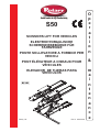 1
1
-
 2
2
-
 3
3
-
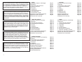 4
4
-
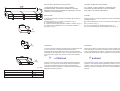 5
5
-
 6
6
-
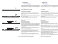 7
7
-
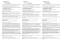 8
8
-
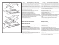 9
9
-
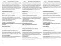 10
10
-
 11
11
-
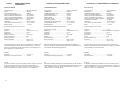 12
12
-
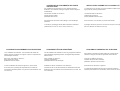 13
13
-
 14
14
-
 15
15
-
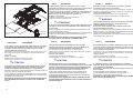 16
16
-
 17
17
-
 18
18
-
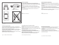 19
19
-
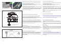 20
20
-
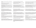 21
21
-
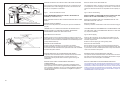 22
22
-
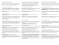 23
23
-
 24
24
-
 25
25
-
 26
26
-
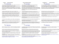 27
27
-
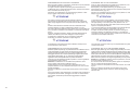 28
28
-
 29
29
-
 30
30
-
 31
31
-
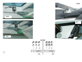 32
32
-
 33
33
-
 34
34
-
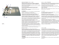 35
35
-
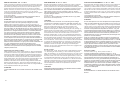 36
36
-
 37
37
-
 38
38
-
 39
39
-
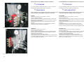 40
40
-
 41
41
-
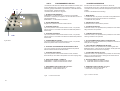 42
42
-
 43
43
-
 44
44
-
 45
45
-
 46
46
-
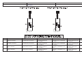 47
47
-
 48
48
-
 49
49
-
 50
50
-
 51
51
-
 52
52
-
 53
53
-
 54
54
-
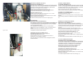 55
55
-
 56
56
-
 57
57
-
 58
58
-
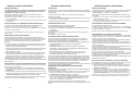 59
59
-
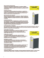 60
60
-
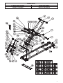 61
61
-
 62
62
-
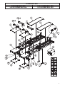 63
63
-
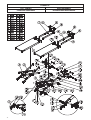 64
64
-
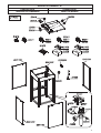 65
65
-
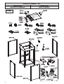 66
66
-
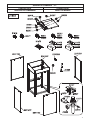 67
67
-
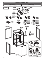 68
68
-
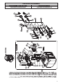 69
69
-
 70
70
-
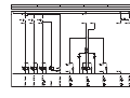 71
71
-
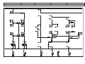 72
72
-
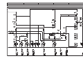 73
73
-
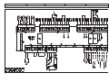 74
74
-
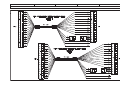 75
75
-
 76
76
-
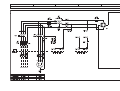 77
77
-
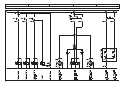 78
78
-
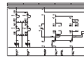 79
79
-
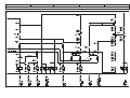 80
80
-
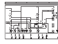 81
81
-
 82
82
-
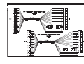 83
83
-
 84
84
-
 85
85
-
 86
86
-
 87
87
-
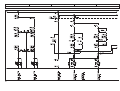 88
88
-
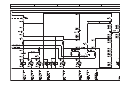 89
89
-
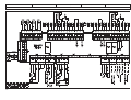 90
90
-
 91
91
-
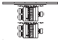 92
92
-
 93
93
-
 94
94
-
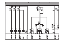 95
95
-
 96
96
-
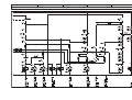 97
97
-
 98
98
-
 99
99
-
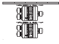 100
100
-
 101
101
-
 102
102
-
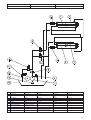 103
103
-
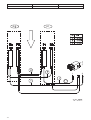 104
104
-
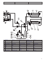 105
105
-
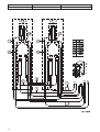 106
106
-
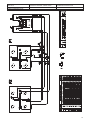 107
107
-
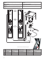 108
108
-
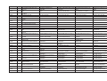 109
109
-
 110
110
-
 111
111
-
 112
112
-
 113
113
-
 114
114
-
 115
115
-
 116
116


Rotary VAS 791021 Owner's manual
- Type
- Owner's manual
- This manual is also suitable for
Ask a question and I''ll find the answer in the document
Finding information in a document is now easier with AI
in other languages
Related papers
Other documents
-
HOMCOM 835-845V00GY User guide
-
KATOOL KT-X95 User manual
-
Husqvarna PP 345 E Owner's manual
-
Atlas Kwik Bay Installation & Operation Manual
-
Columbus KS 51|BM 45 User manual
-
-
-
Bartscher 190174 Product information
-
Facom DL.50 User manual
-
Beta 3006 Operating instructions