Page is loading ...

English
IOM HAN 01-N-3GB
Part number / Code / Teil Nummer / Codice / Código : 3990513GB
Supersedes / Annule et remplace / Annulliert und ersetzt /
Annulla e sostituisce / Anula y sustituye : IOM HAN 01-N-2GB
Français EspañolDeutsch Italiano
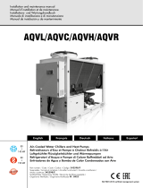
Roof-mouted air conditioning unit
Unite d'air conditionne de toiture
Dachklimagerät
Uunità d’aria condizionata da tetto
Unidad da aire acondicionado de tejado
Installation and maintenance manual
Manuel d’installation et de maintenance
Installations- und Wartungshandbuch
Manuale di installazione e di manutenzione
Manual de instalación y de mantenimiento
IOM HAN 01-N-3
Part number / Code / Teil Nummer / Codice / Código : 3990513
Supersedes / Annule et remplace / Annulliert und ersetzt /
Annulla e sostituisce / Anula y sustituye : IOM HAN 01-N-2
9.8
Ü
31 kW
9.6
Ü
30.5 kW
HAN
10 ÷ 31


INSTALLATION INSTRUCTION
NOTICE D’INSTALLATION
INSTALLATIONSHANDBUCH
ISTRUZIONI INSTALLAZIONE
INSTRUCCIONES DE INSTALACIÓN

2
CONTENTS
GENERAL RECOMMENDATIONS ...............................................................................................................3
SAFETY DIRECTIONS ................................................................................................................................................................ 3
WARNING ............................................................................................................................................................................... 3
EQUIPMENT SAFETY DATA ....................................................................................................................................................... 4
INSPECTION AND STORAGE .....................................................................................................................5
WARRANTY ...............................................................................................................................................5
CONTENTS OF PACKAGE ..........................................................................................................................5
PRESENTATION .........................................................................................................................................5
DIMENSIONS ............................................................................................................................................6
HANDLING ...............................................................................................................................................6
NET WEIGHT ........................................................................................................................................................................... 6
TECHNICAL SPECIFICATIONS ....................................................................................................................7
REFIGERATION SPECIFICATIONS .............................................................................................................................................. 7
ELECTRICAL SPECIFICATIONS ................................................................................................................................................... 7
AERAULIC SPECIFICATIONS ...................................................................................................................................................... 7
OPERATING LIMITS .................................................................................................................................................................. 8
INSTALLATION ..........................................................................................................................................9
PLACE OF INSTALLATION AND REQUIREMENTS ........................................................................................................................ 9
CLEARANCE ............................................................................................................................................................................ 9
ATTACHMENT TO THE GROUND ............................................................................................................................................ 9
CONDENSATE DRAIN PAIN .................................................................................................................................................... 10
AERAULIC CONNECTIONS .................................................................................................................................................... 10
AIR INTAKE AND BLOWING DUCT OUTLET DIMENSIONS ......................................................................................................................... 10
AIR FLOW / PRESSION ADJUSTMENT ........................................................................................................................................................ 11
ELECTRIC HEAT .......................................................................................................................................11
WIRING DIAGRAM AND LEGEND ............................................................................................................12
WIRING DIAGRAM ................................................................................................................................................................. 12
LEGEND ................................................................................................................................................................................ 12
POWER SUPPLY ........................................................................................................................................................................................ 12
WIRING DIAGRAM KEY DESCRIPTIONS .................................................................................................................................................... 12
COOLING / SAFETY......................................................................................................................................................................................................... 12
VENTILATION ................................................................................................................................................................................................................... 12
CONTROL AND REGULATION.......................................................................................................................................................................................... 13
ELECTRIC HEATING KIT .................................................................................................................................................................................................... 13
RANGE AND SETTINGS OF THEMAL PROTECTION / NOMINAL INTENSITY OF THE CONTACTORS (CLASSE AC3) ..................................... 13
COMPRESSOR CRANKCASE HEATER ........................................................................................................................................................ 13
PRESSOSTATS SETTING ........................................................................................................................................................................... 13
COLOUR CODE ...................................................................................................................................................................................... 13
ELECTRICAL CONNECTIONS ...................................................................................................................14
CONNECTION OF RCW2 AND REMOTE ROOM TEMPERATURE ............................................................................................. 15
COMMISSIONING ...................................................................................................................................16
PRE-START CHECK LIST ........................................................................................................................................................... 16
ELECTRICAL CHECK ................................................................................................................................................................................. 16
VISUAL CHECK ........................................................................................................................................................................................ 16
DUCTING ................................................................................................................................................................................................ 16
OPERATING CHECK LIST ........................................................................................................................................................ 17
GENERAL................................................................................................................................................................................................. 17
PHASE ROTATION PROTECTION ............................................................................................................................................................. 17
ELECTRICAL ............................................................................................................................................................................................. 17
OPERATING VOLTAGE: .................................................................................................................................................................................................... 17
CONTROL ....................................................................................................................................................................................................................... 17
AIR BALANCING ...................................................................................................................................................................................... 17
CASE N°1: ....................................................................................................................................................................................................................... 17
CASE N°2: ....................................................................................................................................................................................................................... 17
COMPRESSOR AND REFRIGERATION SYSTEM .......................................................................................................................................... 17
FINAL TASKS ...........................................................................................................................................18
IN CASE OF WARRANTY - MATERIAL RETURN PROCEDURE ....................................................................18
ORDERING SERVICE AND SPARE PARTS ORDER ......................................................................................18
MAINTENANCE .......................................................................................................................................18
REGULAR MAINTENANCE ...................................................................................................................................................... 18
GENERAL INSPECTION .......................................................................................................................................................... 19
OPENING OF ACCESS PANELS .............................................................................................................................................. 19
BLOWER DRIVE SYSTEM ......................................................................................................................................................... 19
COILS ................................................................................................................................................................................... 19
ELECTRICAL SECTION ............................................................................................................................................................ 19
TROUBLE SHOOTING ..............................................................................................................................20

3
POWER SUPPLY MUST BE
SWITCHED OFF
BEFORE STARTING TO
WORK IN THE ELECTRIC
CONTROL BOX
GENERAL RECOMMENDATIONS
Please read the following safety precautions very carefully before installing the unit.
SAFETY DIRECTIONS
Follow the safety rules in forces when you are working on your appliance.
The installation, commissioning and maintenance of these units should be performed by qualified personnel having
a good knowledge of standards and local regulations, as well as experience of this type of equipment.
Given the requirements of pressurising the system and the high current draws involved, this roof-
mounted air conditioning should only be installed by qualified personnel.
The unit should be handled using lifting and handling equipment appropriate to the unit's size and weight.
Given the high refrigerant temperatures present at certain points in the cooling circuit, access to the
area protected by the panels is strictly reserved for qualified personnel only.
Any wiring produced on site must comply with the corresponding national electrical regulations.
Make sure that the power supply and its frequency are adapted to the required electric current of operation, taking
into account specific conditions of the location and the current required for any other appliance connected to the
same circuit.
The unit must be EARTHED to avoid any risks caused by insulation defects.
It is forbidden to start any work on the electrical components if water or high humidity is present on the installation
site.
WARNING
Cutoff power supply before starting to work on the appliance.
The manufacturer declines any responsibility and the warrantly becomes void if these instructions
are not respected.
If you meet a problem, please call the Technical Department of your area.
If possible, assemble the compulsory or optional accessories before placing the appliance on its final location. (see
instructions provided with each accessory).
In order to become fully familiar with the appliance, we suggest to read also our Technical Instructions.
-The informations contained in these Instructions are subject to modification without advance notice.

4
EQUIPMENT SAFETY DATA
Safety Data R410A
Toxicity Low
In contact with skin Skin contact with the rapidly evaporating liquid may cause tissue chilblains. In case of skin contact
with the liquid, warm the frozen tissue with water and call a doctor. Remove contaminated clothing
and footwear. Wash the clothing prior to re-use.
In contact with eyes Vapours have no effect. Liquid splashes or sprays may cause freeze burns. In these cases rinse your
eyes with running water or with a solution for eye lavages for at least 10 minutes. Immediately
apply to a doctor.
Ingestion In this case, burns may result. Do not attempt to make the patient vomit. If the patient is conscious,
rinse the mouth with water. Call a doctor immediately.
Inhalation In case of inhalation, move the patient to an area with fresh air and provide oxygen if ne-
cessary. Perform artificial respiration if the patient has stopped breathing or lacks air. In
case of cardiac arrest, perform external cardiac massage. Call a doctor immediately.
Further Medical Advice Exposure to high concentrations can be dangerous for individuals with cardiac problems, as the
presence of catecholamines such as adrenalin in the bloodstream may lead to increased arrhyth-
mia and possible cardiac arrest.
Occupational exposure
limits
R410A: Recommended limits: 1,000 ppm v/v 8 hours TWA.
Stability Stable product
Conditions to avoid Increased pressure due to high temperatures may cause the container to explode. Keep out of
the sun and do not expose to a temperature >50°C.
Hazardous reactions Possibility of dangerous reactions in case of fire due to the presence of F and/or CI radicals
General precautions Avoid the inhalation of high concentrations of vapours. The concentration in the atmosphere
shall be kept at the minimum value and anyway below the occupational limits. Since vapours
are heavier than air and they tend to stagnate and to build up in closed areas, any opening for
ventilation shall be made at the lowest level.
Breathing protection In case of doubt about the actual concentration, wear breathing apparatus. It should be self-
contained and approved by the bodies for safety protection.
Storage Preservation Refrigerant containers shall be stored in a cool place, away from fire risk, direct sunlight and all
heat sources, such as radiators. The maximum temperature shall never exceed 50°C in the storage
place.
Protection clothes Wear boots, safety gloves and glasses or masks for facial protection.
Behaviour in case of
leaks or escapes
Never forget to wear protection clothes and brething apparatus. Isolate the source of the leakage,
provided that this operation may be performed in safety conditions. Any small quantity of
refrigerant which may have escaped in its liquid state may evaporate provided that the room is
well ventilated.In case of a large leakage, ventilate the room immediately. Stop the leakage with
sand, earth or any suitable absorbing material. Prevent the liquid refrigerant from flowing into
drains, sewers, foundations or absorbing wells since its vapours may create an asphyxiating
atmosphere.
Disposal The best procedure involves recovery and recycle. If this is not possible, the refrigerant shall be
given to a plant which is well equipped to destroy and neutralise any acid and toxic by-product
which may derive from its disposal.
Combustibility features R410A: Non-inflammable at ambient temperatures and atmospheric pressures.
Containers If they are exposed to the fire, they shall be constantly cooled down by water sprays.
Containers may explode if they are overheated.
Behaviour in case of fire In case of fire wear protection clothes and self-contained breathing apparatus.

5
INSPECTION AND STORAGE
At the time of receiving the equipment carefully cross check all the elements against the shipping documents in
order to ensure that all the crates and boxes have been received. Confirmation of the type of unit ordered can be
obtained by reading the maker’s plate.
Inspect the units for any visible or hidden damage.
In the event of shipping damage, write precise details of the damage on the shipper’s delivery note
and send immediately a registered letter to the shipper within 48 hours, clearly stating the damage
caused. Forward a copy of this letter to the manufacturer or their representative.
Never store or transport the unit upside down. Protect unit at the job side from domages made by others. When
unit is stored on the ground, avoid mud store unit leveled.
CONTENTS OF PACKAGE
1 HAN
1 Installation and maintenance manual
1 Control manual
WARRANTY
The appliances are delivered fully assembled, factory tested and ready to operate.
Any modification to the units without the manufacturer’s prior approval, shall automatically render the warranty
null and void.
The following conditions must be respected in order to maintain the validity of the warranty:
² Commissioning shall be performed by specialised technicians from technical services approved by
the manufacturer.
² Maintenance shall be performed by technicians trained for this purpose.
² Only Original Equipment spare parts shall be used.
² All the operations listed in the present manual shall be performed within the prescribed schedule.
THE WARRANTY SHALL BE NULL AND VOID IN THE EVENT
OF NON-COMPLIANCE WITH ANY OF THE ABOVE CONDITIONS.
PRESENTATION
The machine has been designed for an outdoor application, ensuring perfectly weatherproof circulation of the air
in the air treating compartments.
The HAN features a compact design and has an optimal foot print/weight ratio. All units are charged and tested
at the factory and are supplied ready to start for quick and easy installation.

6
DIMENSIONS
HANDLING
SEE APPENDIX
NET WEIGHT
10 13 15 17 19 25 31
Weight Kg 165 219 223 223 243 320 343
The unit can also be lifted by using slings.
A spreader must be used to avoid damaging the casing of the machine.
600
A
178
78
10 13-15-17-19 25-31
A 275 360 425

7
TECHNICAL SPECIFICATIONS
10 13 15 17 19 25 31
Compressor type Scroll Scroll Scroll Scroll Scroll Scroll Scroll
Compressor quantity 1 1 1 1 1 1 1
Number of circuit 1 1 1 1 1 1 1
Refrigerant HFC R410A
Charge of circuit kg SEE NAME PLATE
Units are supplied pre-charged with refrigerant fluid.
This equipment contains fluorinated gas with greenhouse gas effects covered by the Kyoto agreement.
ELECTRICAL SPECIFICATIONS
IMPORTANT
A main fuse must mandatorily be provided on the power supply.
² Fuses not supplied
² Cables not supplied
10 13 15 17 19 25 31
Power supply
3+N /400 /50Hz
Maximum current
A
14 16 17 20 21 29 30
Starting current
A
54 70 69 79 107 119 126
Fuse rating FFG aM
A
16 16 20 20 25 32 32
AERAULIC SPECIFICATIONS
REFIGERATION SPECIFICATIONS
10 13 15 17 19 25 31
INDOOR FAN
Number of fan 1 1 1 1 1 1 1
Type Centrifugal
Drive type Direct Belt / variable pitch pulley
Motor nominal power
input
kW 0.40 0.60 0.75 0.75 1.10 1.10 1.50
Power supply
V/Ph/Hz
230/1/50 230/1/50 400/3/50 400/3/50 400/3/50 400/3/50 400/3/50
Nominal airflow m
3
/h 1930 2640 2940 3190 3860 4780 5530
Available static pressure
(1)
Pa 90 100 170 160 210 240 250
OUTDOOR FAN
Number of fan 1 1 1 1 1 1 1
Type Propeller
Number of blades 5 3 3 3 3 5 5
Fan diameter mm 510 610 610 610 610 710 710
Drive type Direct
Nominal airflow m
3
/h 5200 9000 9000 9000 9000 12000 12000
Motor nominal power
input
kW 0.49 0.49 0.49 0.49 0.49 0.90 0.90
Power supply
V/Ph/Hz
230/1/50 230/1/50 230/1/50 230/1/50 230/1/50 230/1/50 230/1/50
(1) At nominal air flow and at maximum fan speed without air filter

8
10 13 15 17 19 25 31
Cooling mode
Outside temperature
min. for standard
version
°C 15 15 15 15 15 15 15
Outside temperature
min. with all seasons
kit
°C -10 -10 -10 -10 -10 -10 -10
Inside temperature
min. DB/WB
°C 21 / 15 21 / 15 21 / 15 21 / 15 21 / 15 21 / 15 21 / 15
Outside temperature
max..
°C 50 50 50 50 50 50 50
Inside temperature
max. DB/WB
°C 32 / 23 32 / 23 32 / 23 32 / 23 32 / 23 32 / 23 32 / 23
Heating mode
Outside temperature
min.
°C -10 -10 -10 -10 -10 -10 -10
Outside temperature
max. DB
°C 24 24 24 24 24 16 24
Inside temperature
max. DB
°C 27 27 27 27 27 27 27
The All Seasons kits modulates the outdoor fan speed to enable the machine to operate in Cooling mode at outdoor
ambient temperatures as low as -10°C.
DB: Dry Bulb temperature
WB: Wet bulb temperature
OPERATING LIMITS

9
CLEARANCE
ATTACHMENT TO THE GROUND
SEE APPENDIX
INSTALLATION
The unit is not designed to withstand weights or stresses from adjacent equipment, pipe work or
constructions. Any foreign weight or stress on the unit structure could lead to a malfunction or a
collapse with dangerous consequences for personnel and property. In such an event, the warranty
shall be null and avoid.
² The building structure must be capable to carrying the weight of the unit during operation.
² The place of installation must not be subject to flooding.
² The HAN should be installed on a flat, clean surface without any obstacles. The surface area must
be sufficient to spread the weight of the unit over the building structure.
² Ensure that the recommended free clearances around the unit are maintained to avoid any risk of
malfunctions.
² Ensure that there are no obstructions around the condenser or the air outlet to avoid any risk of
recycling old air.
² In addition to the service clearances stated on the dimensions sheet, it is imperative to provide a safe
and appropriate access to the unit for repairs and servicing.
² The installer is responsible for providing the weaterproof seal between the building and the HAN.
The installer must be fully versed in the practice of roof mounted equipments and must comply with
the recommendations and rules detailed in the Technical Directives.
² In order to avoid risk of condensation and energy losses, all outdoor ducting and piping must be
insulated.
PLACE OF INSTALLATION AND REQUIREMENTS
Models 10 13-15-17-19 25-31
A mm 800 800 800
B mm 800 800 800
C mm 800 800 800
D mm 650 850 1000
E mm 3000 3000 3000
A
B
D
E
C

10
CAUTION
For Heatpump models, where the outdoor temperature is likely to fall below +1°C, provide a system to prevent
the syphon from freezing (e.g. heating cord).
CONDENSATE DRAIN PAIN
The installer must imperatively initiate thte syphon action.
75 mm (Mini)
75 mm
2% Mini
Ø1" (25.4 mm)
A
30
10 13-15-17-19 25-31
A 146 156 156
Syphon to be supplied
by the installer
AERAULIC CONNECTIONS
A
B
C
D
E
F
G
H
A B C D E F G H
10
290 295 157 272 40 535 155 562
13 290 295 110 272 35 765 155 712
15-17-19 320 345 110 316 35 765 155 712
25 320 345 137 316 35 860 155 1030
31 320 345 85 405 35 860 155 1030
AIR INTAKE AND BLOWING DUCT OUTLET DIMENSIONS

11
ELECTRIC HEAT
If the unit is to be equipped with an electric heating kit, the latter must be installed on the blown air duct inside
the building.
Safety devices (automatic and manual reset thermostats) protect the appliance against any possible risks of
overheating due to insufficient flow around the shielded elements.
The electric heating kit power supply must be separated from the HAN unit's power supply. Only the electric heating
control functions are managed by the HAN unit (refer to appended wiring diagrams).
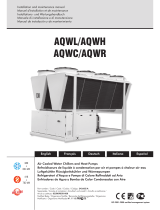
AIR FLOW / PRESSION ADJUSTMENT
SEE TO APPENDED AERAULIC CHARACTERISTICS
The HAN models 10 and 13 are equipped with direct drive centrifugal compressors.
From HAN model 15 upwards, air flow / static pressure is adjusted via a variable pulley. When adjusting this pulley
it is important to ensure that the drive belt is positioned correctly. The latter must not move out of its groove or be
located at the bottom of the groove. The pulley/drive belt assembly must be perfectly aligned and the belt must be
properly tightened in accordance with specifications.
10 mm maxi.
5 kg
90
For a quick check, make sure that the small
rope touch each end of the pulleys as shown
on drawing above.
Belt alignment Belt tensioning
The HAN roof-mounted units are designed for ducted applications. In the event of an application
without a duct network on the blowing side ("free" blowing) it is necessary to create an artificial pressure
loss on the blowing side to avoid damage to the fan motor due to an abnormally high current draw.
This pressure loss can be created for example by adding a perforated plate that will also have the
effect of improving blown air distribution.
To achieve optimal performance, this plate should be of an adequate size and suitably positioned to ensure that
the airflow is close to the unit's nominal airflow.
Perforated plate
(air distributor)

12
LEGEND
N771
WIRING DIAGRAM
SEE APPENDIX
POWER SUPPLY
This supply is protected upstream by an FFG general supply fuse holder, to be provided by the installer, in accordance
with "ELECTRICAL SPECIFICATIONS".
The electrical installation and the wiring of this unit shall comply with local electrical installation standards.
² Three phase 400 V~ + Neutral + Ground:
On terminals PE, N, L1, L2, L3 on the Q1 mains supply circuit switch.
On the ground screw for the earth cable.
WIRING DIAGRAM KEY DESCRIPTIONS
COOLING / SAFETY
WIRING DIAGRAM AND LEGEND
SE 3676 HAN 10/13 400V/230V +/- 10% 50Hz
SE 3678 HAN 15/17/19 400V/230V +/- 10% 50Hz
SE 3679 HAN 25/31 400V/230V +/- 10% 50Hz
FFG : Protective fuses (not supplied)
Q1 : Mains supply circuit switch
K1 : M1 compressor power circuit contactor
KA1 : Three-phase network control relay (phase sequence and cut-out)
HP1 : Automatic reset high-pressure pressostats
LP1 : Automatic reset low-pressure pressostats
M1 : Compressor
R1 : M1 compressor crankcase heater
RV1 : Cycle inversion valve (option)
VENTILATION
MO1 : Outdoor fan motor
CO1 : Outdoor fan motor condenser
FO1 : MO1 motor internal protection
MI3 : Indoor fan motor
K3 : MI3 contactor.
FT3: MI3 thermal relay.

13
CONTROL AND REGULATION
PRESSOSTATS SETTING
LP1 : Factory low pressure adjustment 2bars (29PSI)
HP1 : Factory high pressure adjustment 42bars (609.16PSI)a
RANGE AND SETTINGS OF THEMAL PROTECTION / NOMINAL INTENSITY OF THE
CONTACTORS (CLASSE AC3)
RT : Ambient temperature probe (option)
ICT : Indoor exchanger temperature probe
OCT : Outdoor exchanger temperature probe
SM1 : Remote ON/OFF switch (not supplied) (remove the "SHM" shunt on the circuit board)
K5/6 : Heating elements power contactors
FM5/6 : Heating manual reset safety thermostat
FA5/6 : Heating automatic reset safety thermostat
ELECTRIC HEATING KIT
10 13 15 17 19 25 31
thermal relay
FT3 Range / / 1.8-2.6A 1.8-2.6A 1.8-2.6A 2.6-3.7A 2.6-3.7A
Adjustment / / 1.9A 1.9A 2.5A 2.6A 3.4A
Contactor AC3
K1 9A 12A 18A 18A 18A 25A 25A
K3 / / 9A 9A 9A 9A 9A
COLOUR CODE
BK : Black OG : Orange GNYE : Green/Yellow
BN : Brown WH : White RD : Red
BU : Blue GY : Grey VT : Violet
YE : Yellow
COMPRESSOR CRANKCASE HEATER
10 13 15 17 19 25 31
Power w 70 70 70 70 70 90 90

14
ELECTRICAL CONNECTIONS
WARNING
BEFORE CARRYING OUT ANY WORK ON THE
EQUIPMENT, MAKE SURE THAT THE ELECTRICAL
POWER SUPPLY IS DISCONNECTED AND THAT THERE
IS NO POSSIBILITY OF THE UNIT BEING STARTED
INADVERTENTLY.
NON-COMPLIANCE WITH THE ABOVE INSTRUCTIONS
CAN LEAD TO INJURY OR DEATH BY ELECTROCUTION.
The electrical installation must be performed by a fully qualified electrician, and in accordance with local electrical
standards and the wiring diagram corresponding to the unit model.
Any modification performed without our prior authorisation may result in the unit’s warranty being declared null
and void.
The power supply cable section must be sufficient to provide the appropriate amperage to the unit’s main power
terminals, at start-up and under full load operating conditions.
The power supply cable shall be selected in accordance with the following criteria:
1. Power supply cable length.
2. Maximum unit starting current draw – the cables shall supply the appropriate amperage to the unit
terminals for starting.
3. Power supply cables’ installation mode. (do not leave cable weight hang on connecting lugs)
4. Cables’ capacity to transport the total system current draw.
Short circuit protection shall be provided by others. This protection shall comprise fuses or circuit breakers with
high breaking capacity, mounted on the distribution board. The distribution board must support the intensity of the
whole of the machines installed.
VERY IMPORTANT:
3N~400V-50Hz +
The outdoor unit is equipped as standard with a phase sequence and cut-out controller located in the electrical
box.
THIS PRODUCT IS EQUIPPED WITH A PHASE SEQUENCE CONTROLLER. THE LED’s INDICATE THE
FOLLOWING CONDITIONS:
Green LED = 1
Yellow LED =1
Low voltage supply
The compressor rotation
direction is correct
Green LED = 1
Yellow LED =0
Phase inversion or phase absent
(L1)
The compressor and the fans
do not start.
Green LED = 0
Yellow LED =0
Phase absent (L2 or L3)
the compressor and the fans do
not start.

15
Use a pozidrive M3.5 screwdriver, Form Z, to make the connections.
These units are equipped with a local switch used as general terminal board.
The proximity switch can be mounted at two different locations:
The switch can be padlocked.
A circuit breaker or fuse holder ( not supplied ) must be installed on the main power
supply of the unit in accordance with the circuit diagram; for the raitings, refer to the
electrical specifications.
3N~400V
CONNECTION OF RCW2 AND REMOTE ROOM TEMPERATURE
100 m MAXI
1 mm² MAXI
Shielded cable
RS485
GND
12v
12V
GND
1
2
RT
GND
IF the RT sensor is not used, the RCW2 must be configured in Zone 1 with the local temperature function
activated.
Remote room temperature
sensor delivred with
the machine (optional
installation)
1000 m MAXI
Shielded 2 twisted pairs cable
with setting with terminal GND.
0,12 à 0,3 mm²

16
COMMISSIONING
PRE-START CHECK LIST
ELECTRICAL CHECK
1. Electrical installation has been carried out according to unit wiring diagram and the Supply Authority
Regulations.
2. size fuses or circuit breaker has been installed at the main switchboard.
3. Supply voltages as specified on unit wiring diagram.
4. All cables are properly identified and tight connected at the unit.
5. That the wiring is not in contact with surfaces subject to high temperatures or sharp angles, or is
protected against such risks.
VISUAL CHECK
1. Clearances around unit including outdoor air entry and discharge openings and service accesses.
2. Unit mounted as specified.
3. For loose or missing bolts or screws.
4. For refrigerant leaks in connections and components.
5. All panels are in place and secured.
6. The unit is clean and free of any extraneous installation materials.
DUCTING
1. Connections flexible type, secure and detachable for service access.
2. Fan drive from HAN model 15 upwards
Correct variable diameter pulley adjustment guaranteeing the intended air quantity and static pressure
(see § "AIR FLOW / PRESSURE ADJUSTMENT").
3. Check that the fan shaft and motor pulleys are mounted correctly and turn true.
4. Ensure that both pulley grooves are correctly aligned. Improper alignment of the pulleys and belt may
cause vibration in the blower drive and result in premature wear and noise.

17
AIR BALANCING
A variable pulley is fitted to the motor shaft in order to adjust the blower performance to the pressure drop at the duct
work. The pulley must be adjusted when the measured external static pressure and air volume (motor current draw)
differ from the nominal values at the unit. As a default setting, the variable diameter pulley is open by 2 turns.
CASE N°1:
The measured air flow is higher than the nominal air flow. You must reduce the fan rotation speed by opening the
variable diameter pulley. It is imperative to adjust the pulley, otherwise the motor’s internal protection will trigger
because of overheating taking the entire unit out of operation.
CASE N°2:
The measured air flow is lower than the nominal air flow. You must increase the fan rotation speed by closing the
variable diameter pulley.
OPERATING CHECK LIST
GENERAL
Cheek for any unusual noises or vibration in the running components, particularly at the main blower.
PHASE ROTATION PROTECTION
If the phase at the power supply are not correct, the phase rotation protection device will prevent the machine
from starting.
ELECTRICAL
OPERATING VOLTAGE:
Recheck voltage at unit supply terminals.
CONTROL
1. Operate system and thermostat switches.
2. Check unit is wired for correct control of blower, cooling and heating modes.
3. Verify all sensor signal, using the controller display.
COMPRESSOR AND REFRIGERATION SYSTEM
1. If outdoor air temperature is below 0°C make sure that the compressor crankcase heater has been
on for at least one hour before starting compressor.
2. Running check: Start the compressor. Check for any unusual noise or vibration.
3. Operating Pressures: Operate the unit for at last 20 minutes and ensure that the refrigerant pressures
are stabilised, and cheek that they are within the normal operating ranges.
4. Operating Temperature: Check discharge, suction and liquid temperatures.
5. Compressor output temperature in cooling mode should not normally exceed 105° C.
6. Compressor intake air superheating must be between 5° K and 12° K.
This section applies to all HAN from model 15.

18
The user is responsible for ensuring that it is in a proper working condition and that technical installation
as well as the regular maintenance operations are performed by properly trained technicians and in
accordance with the instructions contained in this manual.
MAINTENANCE
REGULAR MAINTENANCE
These units have been designed to require only minimal servicing, thanks to the use of a maximum number of
lubricated-for-life components. Nevertheless, certain regular servicing operations are necessary to guarantee
optimal system operation.
Servicing must be performed by experienced and qualified personnel only.
WARNING : Isolate unit from main power supply before working on unit.
FINAL TASKS
Operate the air conditioner in the presence of the user and explain all functions.
As required, demonstrate filter removal, cleaning and replacement.
IN CASE OF WARRANTY - MATERIAL RETURN PROCEDURE
Material must not be returned without permission of our After Sales Department.
To return the material, contact your nearest sales office and ask for a "return form". The return form shall be sent
with the returned material and shall contain all necessary information concerning the problem encountered.
The return of the part is not an order for replacement. Therefore, a purchase order must be entered through your
nearest distributor or regional sales office. The order should include part name, part number, model number and
serial number of the unit involved.
Following our personal inspection of the returned part, and if it is determined that the failure is due to faulty material
or workmanship, and in warranty, credit will be issued on customer's purchase order. All parts shall be returned to
our factory, transportation charges prepaid.
ORDERING SERVICE AND SPARE PARTS ORDER
The part number, the order confirmation and the unit serial number indicated on the name plate must be provided
whenever service works or spare parts are ordered.
For any spare part order, indicate the date of unit installation and date of failure. Use the part number provided
by our service spare parts, if it not available, provide full description of the part required.
IT IS RECOMMENDED THAT THE DISCONNECT SWITCH BE PADLOCKED
CAUTION
BEFORE CARRYING OUT ANY OPERATION ON THE EQUIPMENT, CHECK
THAT THE ELECTRICAL POWER SUPPLY IS SWITCHED OFF AND THAT IT
CANNOT BE SWITCHED ON INADVERTENTLY.
/