Aeg-Electrolux 135H92RB Owner's manual
- Category
- Lawnmowers
- Type
- Owner's manual

Instruction manual
Please read these instructions care-
ful ly and make sure you un der stand
them before using this ma chine.
Anleitungshandbuch
Bitte lesen Sie diese Anleitungen sorg-
fältig durch und vergewissern Sie sich,
daß Sie diese verstehen, bevor Sie die
Maschine in Betrieb nehmen.
Manuel d’instructions
Merci de lire trés attentivement le
manuel d'instructions. Assurez-vous
d'avoir tout compris avant d'utiliser ce
tracteur.
Manual de las instrucciones
Por favor lea cuidadosamente y com-
prenda estas intrucciones antes
de usar esta maquina.
Manuale di istruzioni
Prima di utilizzare la macchina leggete
queste istruzioni con attenzione ed ac-
certatevi di averle comprese bene.
Instructieboekje
Lees deze instructies aandachtig en
zorg dat u ze begrijpt voordat u deze
machine gebruikt.
02227_PL_LT_CRD
BL14536RBH
BL14592RBH
BL16536RBHK
BL16592BHK
CRDH135-92
CRDH145-36
CRDH155-42
CRDH165-107
CRDH180-42
CRDH180-107
MI145HCRD
M180HCRD
MBA16H107BR
MC135TH92RB
P145H107RB
P18H107RB
RE145H92RB
RE155H107RB
REB145HRB
REN145HRB
REN145THRB
REQ145HRB
WZ145H92RB
WZ155H107RB
WZ18H107RB
135H92RB
165H107RB

2
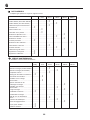
We reserve the right to make changes without prior notice.
Ånderungen ohne vorherige Mitteilung sind vorbehalten.
Nous nous réservons le droit d'apporter des modifi cations sans avis préalable.
Nos reservamos el derecho a introducir modifi caciones sin previo aviso.
Ci riserviamo il diritto di modifi che o cambiamenti senza preavviso.
Wij houden ons het recht voor om veranderingen aan te brengen zonder voorafgaande
mededeling.
1
2
3
4
5
6
7
8
3
18
37
46
49
61
82
85
Safety rules. Reglas de seguridad.
Sicherheitsvorschriften. Norme antinfortunistiche.
Règles de sécurité. Veiligheidsregels.
Assembly. Montaje.
Zusammenbau. Montaggio.
Montage. Montering.
Functional description. Descripción del funcionamiento.
Funktionsbeschreibung. Funzionamento.
Description du fonctionnement. Beschrijving van functies.
Before starting. Antes del arranque.
Maßnahmen vor dem Anlassen. Prima dell’avviamento.
Avant de démarrer. Maatregelen vóór het starten.
Driving. Conducción.
Betrieb. Guida.
Conduite. Rijden.
Maintenance, adjustment. Mantenimiento, ajuste.
Wartung (Instandhaltung), Einstellung. Manutenzione.
Entretien, réglages. Onderhoud, afstelling.
Troubleshooting. Búsqueda de averías.
Störungssuche. Ricerca guasti.
Recherche des pannes. Het localiseren van fouten.
Storage. Conservación.
Aufbewahrung. Rismessaggio.
Remisage. Stallen.

3
I. Training
• Read the instructions carefully. Be familiar with the con trols
and the proper use of the equipment.
• Never allow children or people unfamiliar with the ins truc -
tions to use the lawnmower. Local regulations may restrict
the age of the operator.
• Never mow while people, especially children, or pets are
nearby.
• Keep in mind that the operator or user is responsible for
accidents or hazards occurring to other people or their
property.
Do not carry passengers.
• All drivers should seek and obtain professional and prac-
ti cal instruction. Such instruction should em pha size:
- the need for care and concentration when work ing
with ride-on machines;
- control of a ride-on machine sliding on a slope will
not be regained by the application of the brake.
The main reasons for loss of control are:
a) insuffi cient wheel grip;
b) being driven too fast;
c) inadequate braking;
d) the type of machine is unsuitable for its task;
e) lack of awareness of the effect of ground
conditions,especially slopes;
f) incorrect hitching and load distribution.
II. Preparation
• While mowing, always wear substantial footwear and long
trousers. Do not operate the equipment when barefoot
or wearing open sandals.
• Thoroughly inspect the area where the equipment is to
be used and remove all objects which may be thrown by
the machine.
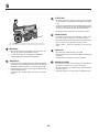
• WARNING - Petrol is highly fl ammable.
- Store fuel in containers specifi cally de signed for this
pur pose.
- Refuel outdoors only and do not smoke while re fu -
el ing.
- Add fuel before starting the engine. Never remove
the cap of the fuel tank or add petrol while the engine
is running or when the en gine is hot.
- If petrol is spilled, do not attempt to start the engine
but move the machine away from the area of spillage
and avoid cre at ing any source of ig ni tion until petrol
vapors have dis si pat ed.
- Replace all fuel tanks and container caps securely.
• Replace faulty silencers.
• Before using, always visually inspect to see that the
blades, blade bolts and cutter assembly are not worn or
damaged. Replace worn or damaged blades and bolts
in sets to preserve balance.
• On multi-bladed machines, take care as rotating one blade
can cause other blades to rotate.
III. Operation
• Do not operate the engine in a confi ned space where
dan ger ous carbon monoxide fumes can collect.
• Mow only in daylight or in good artifi cial light.
• Before attempting to start the engine, disengage all blade
attachment clutches and shift into neutral.
• Do not use on slopes of more than 10°.
• Remember there is no such thing as a “safe” slope. Travel
on grass slopes requires particular care. To guard against
overturning;
- do not stop or start suddenly when going up or down-
hill;
- engage clutch slowly, always keep machine in gear,
especially when traveling down hill;
- machine speeds should be kept low on slopes and
during tight turns;
- stay alert for humps and hollows and oth er hidden
haz ards;
- never mow across the face of the slope, unless the
lawnmower is designed for this pur pose.
• Use care when pulling loads or using heavy equipment.
- Use only approved drawbar hitch points.
- Limit loads to those you can safely control.
- Do not turn sharply. Use care when re vers ing.
- Use counterweight(s) or wheel weights when sug-
gest ed in the instruction hand book.
• Watch out for traffi c when crossing or near roadways.
• Stop the blades from rotating before crossing surfaces
other than grass.
• When using any attachments, never direct discharge of
material toward bystanders nor allow anyone near the
machine while in operation.
• Never operate the lawnmower with defective guards,
shields or without safety protective devices in place.
• Do not change the engine governor settings or overspeed
the engine. Operating the engine at excessive speed may
increase the hazard of personal injury.
• Before leaving the operator’s position:
- disengage the power take-off and lower the at tach -
ments;
- change into neutral and set the parking brake;
- stop the engine and remove the key.
• Disengage drive to attachments, stop the engine, and
dis con nect the spark plug wire(s) or remove the ignition
key
- before cleaning blockages or unclogging chute;
- before checking, cleaning or working on the lawn-
mower;
- after striking a foreign object. Inspect the lawnmower
for damage and make repairs before re start ing and
op er at ing the equip ment;
- if the machine starts to vibrate abnormally (check
im me di ate ly).
• Disengage drive to attachments when transporting or not
in use.
1. Safety Rules
Safe Operation Practices for Ride-On Mowers
IMPORTANT: THIS CUTTING MACHINE IS CAPABLE OF AMPUTATING HANDS AND FEET AND THROWING OBJECTS. FAILURE
TO OBSERVE THE FOLLOWING SAFETY INSTRUCTIONS COULD RESULT IN SERIOUS INJURY OR DEATH.

4
• Stop the engine and disengage drive to attachment
- before refueling;
- before removing the grass catcher;
- before making height adjustment unless ad just ment
can be made from the op er a tor’s position.
• Reduce the throttle setting during engine run-out and, if
the engine is provided with a shut-off valve, turn the fuel
off at the conclusion of mowing.
IV. Maintenance and Storage
• Keep all nuts, bolts and screws tight to be sure the equip-
ment is in safe working condition.
• Never store the equipment with petrol in the tank inside
a building where fumes may reach an open fl ame or
spark.
• Allow the engine to cool before storing in any enclo-
sure.
• To reduce the fi re hazard, keep the engine, silencer, bat-
tery compartment and petrol storage area free of grass,
leaves, or excessive grease.
• Check the grass catcher frequently for wear or de te -
ri o ra tion.
• Replace worn or damaged parts for safety.
• If the fuel tank has to be drained, this should be done
outdoors.
• On multi-bladed machines, take care as rotating one blade
can cause other blades to rotate.
• When machine is to be parked, stored or left unattended,
lower the cutting means unless a positive mechanical lock
is used.
WARNING: Always disconnect spark plug wire and
place wire where it cannot contact spark plug in
order to prevent ac ci den tal start ing when setting
up, trans port ing, ad just ing or making re pairs.
Page is loading ...
Page is loading ...
Page is loading ...
Page is loading ...
Page is loading ...
Page is loading ...
Page is loading ...
Page is loading ...
Page is loading ...

14
- nadat u een ongewenst voorwerp heeft geraakt.
Inspecteer de maaimachine op schade en voer
reparaties uit voordat u de machine weer start en
gebruikt;
- als de machine abnormaal begint te trillen (onmid-
dellijk controleren).
- vor dem Entfernen von Verstopfungen aus dem Mäh-
werk oder dem Auswurf;
• Schakel de aandrijving naar de hulpstukken uit tijdens
transport of als ze niet worden gebruikt.
• Stop de motor en schakel de aandrijving naar het hulpstuk
uit,
- voordat u tankt;
- voordat u de opvangzak verwijdert;
- voordat u de hoogte verstelt tenzij de hoogte vanuit
de bestuurdersplaats kan worden ingesteld.
• Minder gas tijdens het uitlopen van de motor, en als de
motor met een afsluitklep is uitgerust, moet u de brand-
stoftoevoer aan het einde van het maaien afsluiten.
IV. ONDERHOUD EN OPSLAG
• Houd alle moeren, bouten en schroeven goed vastge-
draaid zodat u er zeker van kunt zijn dat de machine in
een veilige bedrijfsstaat verkeert.
• Sla de machine nooit in een gebouw op, waar dampen een
open vlam of vonk kunnen bereiken, terwijl zich benzine
in de tank bevindt.
• Laat de motor afkoelen voordat u hem in een besloten
ruimte opbergt.
• Beperk brandgevaar: houd de motor, geluiddemper, ac-
curuimte en benzine-opslagruimte vrij van gras, bladeren
of een overmaat aan smeervet.
• Controleer de opvangzak vaak op slijtage of verwering.
• Vervang versleten of beschadigde onderdelen om
veiligheidsredenen.
• Als de brandstoftank afgetapt moet worden, moet dit
buiten worden gedaan.
• Op machines met meerdere messen dient u eraan te
denken dat het draaien van één mes andere messen kan
doen draaien.
• Wanneer de machine moet worden geparkeerd, opgesla-
gen of alleen moet worden gelaten, moet de maai-inrichting
neergelaten worden tenzij een mechanische vergrendeling
wordt gebruikt.
WAARSCHUWING: Maak de bougiekabel altijd
los, plaats hem waar hij de bougie niet kan raken
teneinde onverhoeds starten te voorkomen tijdens
het opstellen, vervoeren, afstellen of uitvoeren van
reparaties.

15
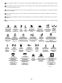
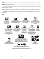
These symbols may appear on your machine or in the literature supplied with the product. Learn and understand their meaning.
Diese Symbole fi nden Sie auf Ihrer Maschine oder in Unterlagen, die mit dem Produkt ausgehändigt wurden. Bitte machen Sie
sich mit deren Bedeutung vertraut.
Ces symboles peuvent fi gurer sur tracteur ou dans les publications fournies avec le produit. Apprenez à comprendre la signifi ca-
tion de ces symboles.
Estos símbolos pueden aparecer sobre su unidad o en la literatura proporcionada con el producto. Aprenda y comprenda sus
signifi cados.
Simboli utilizzati sull'apparato di taglio o nella documentazione fornita unitamente al prodotto. E' importante conoscerne bene il
signifi cato.
Deze symbolen kunnen op uw machine of in de bij het produkt geleverde documentatie aanwezig zijn. Lees en begrijp de betek-
enis.
BATTERY
BATTERIE
BATTERIE
BATERÍA
BATTERIA
ACCU
CAUTION
VORSICHT
DANGER
PRECAUCIÓN
ATTENZIONE
OPGELET
BEWARE OF
THROWN OBJECTS
VORSICHT, HOCHGESCHLEUDERT
GEGENSTÄNDE
ATTENTION AUX PROJECTILES
CUIDADO CON
OBJETOS LANZADOS
ATTENZIONE AGLI OGGETTI
SCAGLIATI
LET OP WEGGESLINGERDE
VOORWERPEN
FORWARD
VORWÄRTSGANG
MARCHE AVANT
MARCHA HACIA
DELANTE MARCIA
VOORUIT
FAST
SCHNELLFAHRT
VITESSE RAPIDE
MARCHA RÁPIDA
AVANZAMENTO VELOCE
VELOCE
SLOW
LANGSAMFAHRT
VITESSE LENTE
MARCHA LENTA
AVANZAMENTO LENTO
LANGZAAM RIJDEN
ENGINE ON
MOTOR LÄUFT
MOTEUR EN MARCHE
MOTOR ENCENDIDO
MOTORE ACCESO
MOTOR AAN
ENGINE OFF
MOTOR AUS
MOTEUR ARRÊTÉ
MOTOR APAGADO
MOTORE SPENTO
MOTOR UIT
OIL PRESSURE
ÖLDRUCK
PRESSION D'HUILE
PRESIÓN DEL ACEITE
PRESSIONE DELL'OLIO
OLIEDRUK
CLUTCH
KUPPLUNG
EMBRAYAGE
EMBRAGUE
FRIZIONE
KOPPELING
LIGHTS ON
LICHT AN
PHARES ALLUMÉS
LUCES ENCENDIDAS
LUCI ACCESE
LICHTEN AAN
FUEL
KRAFTSTOFF
CARBURANT
COMBUSTIBLE
CARBURANTE
BRANDSTOF
CHOKE
STARTKLAPPE
STARTER
ESTRANGULACIÓN
STARTER
CHOKE
MOWER HEIGHT
MÄHWERKHÖHE
HAUTEUR DE COUPE
ALTURA DE LA SEGADORA
ALTEZZA APPARATO
FALCIANTE
MAAIHOOGTE
PARKING BRAKE LOCKED
FESTSTELLBREMSE VERRIEGELT
FREIN DE PARKING VERROUILLÉ
FRENO DE ESTACIONAMIENTO
CERRADO
FRENO DI PARCHEGGIO INNESTATO
PARKEERREM GEBLOKKEERD
UNLOCKED
ENTRIEGELT
DEVERROUILLÉ
ABIERTO
DISINNESTATO
GEDEBLOKKEERD
REVERSE
RÜCKWÄRTSFAHRT
MARCHE ARRIÈRE
MARCHA ATRÁS
RETROMARCIA
ACHTERUIT-RIJDEN
NEUTRAL
LEERLAUF
POSITION NEUTRE
PUNTO NEUTRO
FOLLA
NEUTRAALSTAND
HIGH
HOCH
HAUT
ALTO
AUMENTARE
HOOG
LOW
NIEDRIG
BAS
BAJO
DIMINUIRE
LAAG
ATTACHMENT
CLUTCH ENGAGED
ANBAUGERÄTE-KUPPLUNG
EINGEKUPPELT
LAMES EMBRAYÉES
EMBRAGUE DEL ACCESORIO
ENGANCHADO
FRIZIONE ACCESSORIE
INNESTATA
KOPPELING HULPSTUK
INGESCHAKELD
PARKING BRAKE
FESTSTELLBREMSE
FREIN DE PARKING
FRENO DE ESTACIONAMIENTO
FRENO DI PARCHEGGIO
PARKEERREM
IGNITION
ZÜNDUNG
ALLUMAGE
IGNICIÓN
AVVIAMENTO
ONTSTEKING
ATTACHMENT
CLUTCH DISENGAGED
ANBAUGERÄTE-KUPPLUNG
AUSGEKUPPELT
LAMES DÉBRAYÉES
EMBRAGUE DEL ACCESORIO
DESENGANCHDO
FRIZIONE ACCESSORI
DISINNESTATA
KOPPELING HULPSTUK
UITGESCHAKELD
P
ENGINE START
ANLASSEN DES MOTORS
DÉMARRAGE DU MOTEUR
ARRANQUE DEL MOTOR
AVVIAMENTO DEL MOTORE
HET STARTEN VAN DE MOTOR
REVERSE
RÜCKWÄRTSFAHRT
MARCHE ARRIÈRE
MARCHA ATRÁS
RETROMARCIA
ACHTERUIT-RIJDEN

16
These symbols may appear on your machine or in the literature supplied with the product. Learn and understand their meaning.
Diese Symbole fi nden Sie auf Ihrer Maschine oder in Unterlagen, die mit dem Produkt ausgehändigt wurden. Bitte machen Sie
sich mit deren Bedeutung vertraut.
Ces symboles peuvent se montrer sur votre machine ou dans les publications fournies avec le produit. Apprenez à comprendre la
signifi cation de ces symboles.
Estos símbolos pueden aparecer sobre su unidad o en la literatura proporcionada con el producto. Aprenda y comprenda sus
signifi cados.
Simboli utilizzati sull'apparato di taglio o nella documentazione fornita unitamente al prodotto. E' importante conoscerne bene il
signifi cato.
Deze symbolen kunnen op uw machine of in de bij het produkt geleverde documentatie aanwezig zijn. Lees en begrijp de betek-
enis.
NO OPERATION
ON SLOPES MORE THAN 10
NICHT AUF ABHÄNGEN MIT
MEHR ALS 10 STEIGUNG BETREIBEN
NE PAS UTILISER SUR DES
PENTES DE PLUS DE 10
NO OPERE SOBRE PENDIENTES
DEMÁSDE10
NON USARE SU PENDII CON
UN'INCLINAZIONE DI OLTRE 10
NIET OP HELLINGEN VAN MEER DAN
10 GEBRUIKEN
KEEP BYSTANDERS AWAY
ZUSCHAUER FERNHALTEN
TENIR LES PASSANTS À DISTANCE
GUÁRDESE LEJOS DE GENTE
TENERE LONTANI I PASSANTI
OMSTANDERS UIT DE
BUURT HOUDEN
EUROPEAN MACHINERY
DIRECTIVE FOR SAFETY
EUROPÄISCHE VERORDNUNG
FÜR MASCHINEN-SICHERHEIT
CONFORME AUX NORMES DE
SÉCURITÉ EUROPÉENNES
DIRECTIVO DE MAQUINARIA
EUROPEO PARA LA SEGURIDAD
NORMATIVE ANTINFORTUNISTICHE
EUROPEE PER MACCHINARI
VEILIGHEIDSRICHTLIJN VOOR
EUROPESE MACHINES
DANGER, KEEP HANDS AND FEET AWAY
GEFAHR, HÄNDE UND FÜSSE FERNHALTEN
DANGER, GARDEZ LES MAINS ET LES PIEDS AU LOIN
PELIGRO, MANTENGA LAS MANOS Y LOS PIES LEJOS
PERICOLO. TENERE LONTANI MANI PIEDI
GEVAAR, HANDEN EN VOETEN UIT DE BUURT HOUDEN
WARNING
WARNUNG
ATTENTION
ADVERTENCIA
PERICOLO
WAARSCHUWING
READ OWNERS MANUAL
BETRIEBSANLEITUNG LESEN
LIRE LE MANUEL
D'INSTRUCTIONS
LEA EL MANUAL DE
INSTRUCCIONES
LEGGERE IL MANUALE
DELL'OPERATORE
GEBRUIKERSHANDLEIDING
LEZEN
MOWER LIFT
MÄHWERKHUB
RELEVAGE DE L'UNITÉ DE COUPE
LEVANTAMIENTO DE LA SEGADORA
SOLLEVAMENTO APPARATO FALCIANTE
MAAIHOOGTEREGELING
FREE WHEEL
FREILAUF
ROUE LIBRE
RUEDA LIBRE
COMANDO DISINNESTO
VRIJWIEL
10
DO NOT OPERATE WITHOUT BAGGER OR DEFLECTOR
NICHT IN BETRIEB NEHMEN OHNE GRASFANGBOX ODER DEFLEKTOR
NE JAMAIS UTILISER SANS BAC OU DÉFLECTEUR
NO PONGA EN MARCHA SIN RECOGEDOR O DEFLECTOR
NONAZIONARE LA MACCHINA SENZA IL CESTO O SENZO IL DEFLETTORE DI SCARICO
ZONDER STORTGOOT OF AFWIJKENDE SPATDOEK NIET OPEREREN
HOT SURFACES
HEISSE OBERFLÄCHEN
SURFACES CHAUDES
SUPERFICIES MUY CALIENTES
SUPERFICIE ROVENTE
HETE OPPERVLAKKEN
MAX
+
_
90N
MAX
+
_
150N
DRAWBAR LOADING
ANHÄNGESCHIENENLAST
CHARGEMENT DE LA BARRE DE TRACTION
CARGA DE LA BARRA DE ENGANCHE
CARICO DI TRAZIONE DELLA BARRA
BELASTING OP TREKHAAK
BRAKE/CLUTCH PEDAL
BREMS / KUPPLUNGSPEDAL
PÉDALE DE FREIN / D’EMBRAYAGE
PEDAL DE FRENO / DE EMBRAGUE
PEDALE FRENO/FRIZIONE
REM / KOPPELINGSPEDAAL
SOUND POWER LEVEL
GERÄUSCHPEGEL
NIVEAU DE PUISSANCE ACCOUSTIQUE
NIVEL DE LA POTENCIA ACÚSTICA
LIVELLO DELLA POTENZA SONORA
GELUIDSNIVEAU

17
GEFAHR
AUGEN SCHÜTZEN
EXPLOSIVE GASE
KÖNNEN ERBLINDUNG
UND KÖRPERVERLET-
ZUNGEN VERURSAC-
HEN.
GEVAAR
OGEN BESCHERMEN
EXPLOSIEVE GASSEN
KUNNEN BLINDHEID
OF LETSEL VERO-
ORZAKEN.
PELIGRO
PROTEJE SUS OJOS
GASES EXPLOSIVOS
PUEDEN CAUSAR CE-
GUE-DAD O LESIONES.
PERICOLO
RIPARARE GLI OCCHI
VAPORI ESPLOSIVI
PUO’ PROVOCARE
CECITA’ O LESIONI
ZU VERMEIDEN:
• FUNKEN
• FEUER
• RAUCHEN
GEEN
• VONKEN
• VUUR
• ROKEN
NO
• CHISPAS
• LLAMAS
• FUMAR
DIVIETO
• SCINTILLE
• FIAMME
• SIGARETTE
AUGEN UNVER-
ZÜGLICH MIT WASSER
AUSSPÜLEN. SOFORT
ÄRZTLICHE HILFE
AUFSUCHEN.
OGEN ONMIDDELLIJK
MET WATER SPOELEN.
SNEL MEDISCHE HULP
INROE-PEN.
LÍMPIESE LOS OJOS
CON UN CHORRO DE
AGUA.OBTENGA AYU-
DAMÉDICA RÁPIDAM-
ENTE.
LAVARE IMMEDIATA-
MENTE GLI OCCHI
CON ACQUA. SOT-
TOPORRE AL PIU’
PRES TO ALLE CURE
DEL MEDICO.
SCHWEFELSÄURE
KANN ERBLINDUNG
ODER SCHWERE VERÄT-
ZUNGEN VERURSACHEN.
ZWAVELZUUR
KAN BLINDHEID OF ERN-
STIGE BRANDWONDEN
VER-OORZAKEN.
ÁCIDO SULFÚRICO
PUEDEN CAUSAR CE-
GUE-DAD O QUEMADU-
RAS MUY GRAVES.
ACIDO SOLFORICO
PUO’ PROVOCARE LA
CECITA’ OD USTIONI
GRAVI.
01738
FÜR KINDER UNZUGÄNGLICH AUFBEWAHREN. NICHT KIPPEN. DIE BATTERIE NICHT ÖFFNEN!
UIT DE BUURT VAN KINDEREN HOUDEN. NIET KANTELEN. DE BATTERIJ NIET OPENMAKEN!
MANTENER FUERA DEL ALCANCE DE NIÑOS. NO LA INCLINE. ¡NO ABRA LA BATERÍA!
TENERE LONTANO DALLA PORTATA DEI BAMBINI. NON INCLINARE. NON APRIRE LA BATTERIA!

18
02601
2. Assembly. 2. Zusammenbau. 2. Montage. 2. Montaje
2. Montaggio. 2. Montage.
1
1
1
1
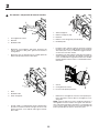
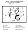
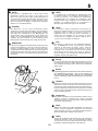
Before the tractor can be used certain parts must be as-
sem bled, which for transportation reasons are enclosed in
the packing.
Vor der Anwendung des Aufsitzmähers müssen gewisse
Teile eingebaut werden, die aus Transportgründen in der
Verpack-ung lose beigefügt sind.
Avant d'utiliser la tondeuse autoportée, certains éléments
livrés dans l'emballage doivent être montés.
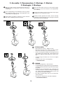
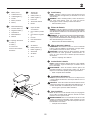
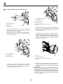
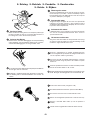
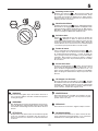
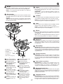
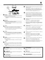
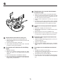
STEERING WHEEL
• Mount extension shaft (1). Tighten securely.
• Mount the main shaft cover. Make sure that the guide
tabs in the cover fi t the cover in respective holes.
• Remove steering wheel adapter from steering wheel and
slide adapter onto steering shaft . Check that the front
wheels are aligned forward and place the wheel on the
hub.
• Assemble large fl at washer and 1/2 hex nut. Tighten
securely.
• Snap insert into center of steering wheel.
1. EX TEN SION SHAFT
LENKRAD
• DieVerlängerungswelle (1). Gut festziehen.
• Lenkwellengehäuse einbauen. Dafür sorgen, daß die Füh-
rungsbolzen in die jeweils dafür vorgesehenen Bohrungen
ein- greifen.
• Nehmen Sie den Lenkradadapter vom Lenkrad ab und
schieben Sie diesen auf die Lenksäulenverlängerung
auf. Prüfen, daß die Vorderräder gerade stehen, und
das Lenkrad auf der Nabe anbringen.
• Die große Unterlegscheibe und die 1/2 kontermutter.
Sicher festziehen.
• Den Einsatz in die Mitte des Lenkrades eindrücken.
1. VERLÄNGERUNGSWELLE
Antes de poder utilizar el tractor, hay que montar algunas
piezas que, por razones de transporte, van empaquetadas
en el embalaje.
Prima di usare il trattore, montare alcune parti che per ragioni
di trasporto sono confezionate a parte.
Voordat de traktor gebruikt kan worden, moeten sommige
onderdelen worden gemonteerd, die vanwege het trans port
apart verpakt zijn in de emballage.
1

19
2
VOLANT DE DIRECTION
• Monter la rallonge de l'arbre de direction (1) en alignant
bien les trous. Bien serrer la vis et l'écrou.
• Positionner le carénage sur la colonne de direction.
S'assurer que les ergots du carénage sont bien placés
dans les trous correspondants du tableau de bord.
• Retirer l'adaptateur cranté du volant et le glisser sur
l'arbre de direction. Vérifi er que les roues avant sont
bien alignées selon l'axe d'avancement et positionner
le volant sur l'adaptateur. La traverse du volant doit être
perpendiculaire à l'axe d'avancement.
• Mettre en place la grande rondelle plate, la rondelle frein
et la vis ou l'écrou hexagonal(e). Serrer fortement.
• Encliqueter l'enjoliveur de volant dans le centre du vo-
lant.
1. RALLONGE DE L'ARBRE DE DIRECTION
VOLANTE DE DIRECCIÓN
• Introduzca el eje de extensión (1). Apriete en forma se-
gura.
• Montar la cubierta del eje del volant. Assegurarse de que
las espigas de guía de la cubierta encajan en los orifi cios
respectivos.
• Remueva el adaptador del volante y deslice el adaptador
sobre la extensión del eje de dirección. Controlar que
las ruedas delanteras están dirigidas hacia adelante y
poner el volante en el cubo.
• Monte una arandela plana grande una terercas de 1/2 y
apriete en forma segura.
• Presione la pieza inserta adentro del centro del volante
de dirección.
1. EJE DE EXTENCIÓN
VOLANTE
• Montare l'albero di estensione (1). Stringere salda-
mente.
• Montare il coperchio del piantone. Controllare che tutti i
pemi di guida entrino nei rispettivi alloggi.
• Rimuovere l’adattatore del volante dal volante e scorrerlo
sull’estensione dell’albero dello sterzo. Controllare che
le ruote anteriori siano ben dritte montare il volante sul
mozzo.
• Assembiare la rondella piatta grande e il dadi 1/2. Tringere
in maniera salda.
• Scattare l'inserto al centro del volante.
1. ALBERO DI ESTENSIONE
HET STUUR
• Monteer de verlengas (1) en deze stevig vast.
• Monteer de stuuraskap. Let erop dat de stuurtaps in de
kap in de respectievelijke gaten vallen.
• Haal de stuuradapter van het stuur af en schuif de adapter
op het verlengstuk van de stuuras. Controleer of de voor-
wielen recht naar voren staan gericht en plaats het stuur
op de naaf.
• Bevestig de grote platte sluitring en de 1/2 borgmoer.
Zet ze stevig vast.
• Klik het inzetstuk in het midden van het stuur.
1. VERLENGAS
1
02466
02701
2
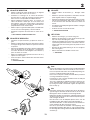
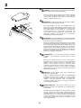
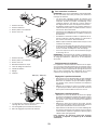
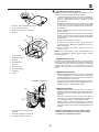
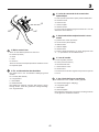
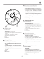
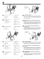
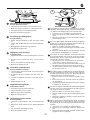
Seat
Remove the hardware securing seat to the cardboard pack ing
and set the hardware aside for assembly of seat to tractor.
Pivot seat upward and remove from cardboard packing. Re-
move the cardboard packing and discard.
Place seat on seat pan so head of shoulder bolt is positioned
over large slotted hole in pan (1).
Push down on seat to engage shoulder bolt in slot and pull
seat towards rear of tractor.
The seat is adjustable for individual setting in relation to the
clutch and brake ped al. Set the seat to the correct position
by moving it forwards or backwards. Tighten the adjustment
bolt securely (2).
Sitz
Entnehmen Sie die Teile, mit denen der Sitz an der Karton-
age befestigt ist. Bewahren Sie diese Teile auf, da sie für die
Montage des Sitzes am Traktor noch benötigt werden.
Kippen Sie den Sitz nun nach oben, und nehmen Sie ihn aus
der Kartonage. Entfernen Sie die restlichen Verpackungsteile
und entsorgen Sie diese.
Der Sitz wird so auf die Sitzplatte plaziert, dass sich der
Hauptbolzen über dem Schlitz in der Platte befi ndet (1).
Sitz herunterdrücken, so dass der Bolzen in den Schlitz ein-
rastet und dann den Sitz nach hinten ziehen.
Der Sitz ist persönlich im Verhältnis zum Kupplungs- bzw.
Bremspedal einstellbar. Den Sitz vor- oder zurückschieben,
bis die richtige Sitz-stellung erhalten wird. Die Einstellschraube
anziehen (2).
1
02617
Page is loading ...

21
2
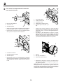
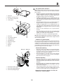
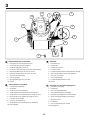
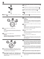
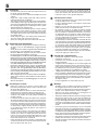
Install battery
NOTE: If battery is put into service after month and year
indicated on label, charge battery for minimum of one hour
at 6-10 amps.
WARNING: Before installing battery remove metal brace-
lets, wrist watch bands, rings, etc. from your person.
Touching these items to battery could result in burns.
• Remove Battery Cover
Einbau der Batterie
HINWEIS: Falls diese Batterie nach dem auf dem Aufkleber
angegebenen Datum (Monat und Jahr) in Betrieb genommen
wird, die Batterie mindestens eine Stunde lang mit 6 bis 10
Ampere aufl aden.
WARNUNG: Vor dem Einbau der Batterie Metallarmbänder,
Uhrarmbänder, Ringe und dgl. ablegen. Wenn diese
Gegenstäande mit der Batterie in Berührung kommen, könnte
dies Brandverletzungen verursachen.
• Entfernen Sie die Batterieabdeckung
Mise en place de la batterie
REMARQUE : Si la batterie est mise en service au-delà de
l'année et du mois indiqués sur l'étiquette, recharger la bat-
terie, pendant une heure au moins, à 6-10 A .
ATTENTION : Avant de mettre en place la batterie, pren dre
la précaution de retirer gourmette, montre-bracelet, an-
neau, etc. Leur contact avec la batterie pouvant entraîner
des brûlures.
• Retirer le capotage de la batterie
Instalación de la batería
NOTA: Si utiliza la bateria después del mes y año indicado
sobre la etiqueta, cargue la batería por un mínimo de una
hora a 6-10 amps.
ADVERTENCIA: Antes de instalar la batería, quitese los
brazaletes metálicos, correas de reloj, sortijas, etc. Si estos
objetos tocan la bateria pueden producirse quemaduras.
• Quite el tapador del acumulador
Installazione della batteria
NOTA: Se questa batteria viene messa in uso dopo il mese
e l’anno indicati sull’etichetta, caricarla per almeno un’ora a
6-10 Ampère.
PERICOLO: Prima di installare la batteria eliminare anelli,
collane,braccialetti e altri oggetti di metallo dalla persona. Il
contatto del metallo con la batteria può causare incendi,
• Portare giuí il coperchio dellíaccumulatore.
Accu installeren
N. B.: Als deze accu na de maand en het jaar, aangegeven
op het etiket, in bedrijf wordt genomen, laad de accu dan
minstens één uur op met 6-10 A.
WAARSCHUWING: Doe voor het intalleren van de accu alle
metalen voorwerpen: armbanden, ringen, horloges enz. Haf.
Anders kan het contact tussen deze voorwerpen en de accu
brandwonden veroorzaken.
• Verwyder het accudeksel.
4
6
5
1
2
3
1. Tapador del
acumulador
2. Cable positivo (+)
3. Cable negativo (-)
4. Protección
5. Terminal de batería
6. Batería
1. Coperchio dellí
accumulatore
2. Cavo elettrico positivo
(+)
3. Cavo elettrico negativo
(-)
4. Paraurti
5. Polo della batteria
6. Batteria
1. Accudeksel
2. Kabel positieve (+)
3. Kabel negatieve (-)
4. Stootwand
5. Accuklem
6. Accu
1. Battery Cover
2. Cable Positive (+)
3. Cable Negative (-)
4. Fender
5. Battery terminal
6. Battery
1. Batterieabdeckung
2. Positives Kabel (+)
3. Negatives Kabel (-)
4. Schutzblech
5. Batterieklemme
6. Batterie
1. Capotage de batterie
2. Câble (+)
3. Câble (-)
4. Carrosserie
5. Borne de la batterie
6. Batterie

22
2
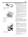
WARNING: Positive terminal must be con nect ed fi rst to
prevent sparks from ac ci den tal grounding.
Remove terminal caps and discard. Connect the red cable
to + and then the black earth ca ble to -. Screw tight the
cables. Grease the battery poles with vaseline to prevent
corrosion. Replace battery cover.
WARNUNG! Um einen Kurzschluß zu vermeiden, muß der
Pluspol zuerst angeschlossen werden.
Die Schutzkappen von den Anschlußklemmen ent-
fernen und entsorgen. Die Batterie in Position neben den
Fahrersitz bringen. Die Batterieklemmen müssen nach
vorn zeigen. Zuerst das rote Kabel an „+“ und dann das
schwarze Kabel an„-“ anschließen. Die kabel fest
anschrauben. Batterieklemmen mit wasserfreiem Fett
(Vaseline) einfetten, um Korrosion zu verhindern.
Batterieabdeckung wieder montieren.
ATTENTION: La borne positive doit être connectée la première
afi n d'éviter les étincelles qui peuvent se produire à la suite
d'une mise à la masse accidentelle.
Retirer les capuchons de protection des bornes et les mettre
de côté. Placer la batterie dans son logement, les bornes du
côté extérieur. Raccorder en premier le câble rouge (+) à la
borne positive de la batterie puis le câble noir (-) à la borne
négative. Fixer les deux câbles à l'aide des vis et des écrous
fournis. Graisser les bornes de la batterie avec une graisse
résistante à l'humidité (vaseline) afi n d'éviter la corrosion.
Replacer le capotage de la batterie.
ADVERTENCIA: A fi n de evitar chispas por contacto
accidental a tierra hay que conectar primero el borne
positivo.
Remueva las tapas protectoras de los terminales y
póngalas de lado. Ponga la batería en su sitio debajo del
asiento. ‘Los bornes han de estar orientados hacia
adelante. Conecte primero el cable rojo al borne positivo
y después el negro de masa al borne negativo. Sujete los
cables. Lubrique los bornes con grasa que no contenga
agua (vaselina) a fi n de evitar la corrosión. Reponga el
tapador del acumulador.
PERICOLO: Il polo positivo deve essere collegato per
primo onde evitare scintille.
Togliere i cappucci protettivi dai poli e scartarli.Montare
la batteria nel vano sotto il sedile, con i poli in avanti.
Collegare il cavo rosso al polo positivo (+) e quello nero
negativo (-) alla terra. Ingrassare i poli con grasso privo
di acqua (vasellina) per evitare corrosione. Rimetter il
coperchiodellíaccumulatore.
WAARSCHUWING: De positieve klem moet eerst
aangesloten worden om vonken door per ongeluk aarden
te voorkomen.
Verwijder de beschermdoppen van de accupolen en gooi
ze weg. Zet de accu op zijn plaats onder de zitting. De
accupolen dienen naar voren te zijn gericht. Sluit eerst de
rode kabel aan op + en daarna de zwarte aard-kabel op
-. Schroef de kabels vast. Smeer de accupolen in met
watervrij vet (vaseline) om corrosie te voorkomen. Plaats
het accudeksel terug.

23
2
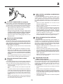
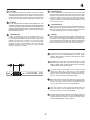
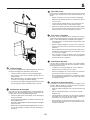
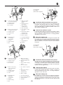
TO ADJUST GAUGE WHEELS (if equipped)
Gauge wheels are properly adjusted when they are slightly
off the ground when mower is at the desired cutting height in
operating position. Gauge wheels then keep the deck in proper
position to help prevent scalping in most terrain con di tions.
• Adjust gauge wheels with tractor on a fl at level surface.
• Adjust mower to desired cutting height.
• With mower in desired height of cut po si tion, gauge wheels
should be assembled so they are slightly off the ground.
In stall gauge wheel in appropriate hole with shoulder bolt,
3/8 washer, and 3/8-16 locknut and tighten se cure ly.
• Repeat for opposite side installing gauge wheel in same
adjustment hole.
EINSTELLEN DER TASTRÄDER
(sofern vorhanden)
Die Tasträder müssen sich in geringem Abstand vom Boden
befi nden, wenn das Mähwerk in Betriebsstellung die gewün-
schte Schnitthöhe aufweist. Die Tasträder halten dann das
Mähwerk in der korrekten Stellung, um in den meisten Terrains
ein Abschuppen zu verhindern.
• Die Tasträder mit dem Traktor auf einer ebenen Fläche
einstellen.
• Den Mäher auf die gewünschte Schnitthöhe einstellen.
• Wenn sich das Mähwerk in der gewünschten Schnit-
thöhe befi ndet, sollten die Tasträder so zusammengebaut
werden, daß sie sich in geringem Abstand vom Boden
befi nden. Das erste Tastrad in die entsprechende Öffnung
einbauen.
• Auf der gegenüberliegenden Seite wiederholen und das
andere Tastrad in dieselbe Einstellöffnung einbauen.
REGLAGE DES ROULETTES DE JAUGE
(si équipé)
Les roulettes de jauge sont correctement réglées lorsqu'elles
se trouvent légèrement au-dessus du sol pendant la tonte, le
carter de coupe étant à la hauteur désirée pour la coupe.
• Régler les roulettes de jauge lorsque le tracteur se trouve
sur un terrain plat.
• Régler le carter de coupe à la hauteur de coupe dési-
rée.
• Lorsque le carter de coupe est à la hauteur souhaitée, la
roulette de jauge doit être placée légèrement au dessus
du sol. Fixer la roulette de jauge dans le trou approprié
du support situé sur le carter de coupe à l'aide de la vis,
de la rondelle plate 3/8 et de l'écrou frein 3/8-16. Serrer
à fond.
• Répéter cette opération pour l'autre côté en plaçant la
seconde roulette dans le trou correspondant à celui utilisé
pour la première roulette de jauge.
PARA AJUSTAR LAS RUEDAS CALIBRADORAS
(si está provisto)
Las ruedas calibradoras están bien ajustadas cuando se en-
cuentran un poco a distancia del terreno al mismo tiempo
que la segadora esté a la altura de corte deseada. Entonces
las ruedas calibradoras mantienen el conjunto segador en
posición para prevenir el corte raspeo en casi todos los ter-
renos.
• Ajuste las ruedas calibradoras con el tractor en una
superfi cie nivelada plana.
• Ajuste la segadora a la altura de corte deseada con la
manilla de ajuste de altura.
• Con la segadora a la altura deseada para la posición de
corte, se tienen que montar las ruedas calibradoras de
modo que queden un poco sobre el suelo. Instale las
ruedas calibradoras en el agujero adecuado con el perno
con resalto, la arandela de 3/8, y la tuerca de seguridad
de 3/8-16 y apriételos en forma segura.
• Repita el procedimiento para el lado opuesto instalando
la rueda calibradora en el mismo agujero de ajuste.
REGOLAZIONE DEI RUOTINI ANTERIORI
(se installato)
La regolazione dei ruotini anteriori può essere eseguita cor-
rettamente se sono leggermente sollevati da terra quando il
tosaerba si trova all’altezza di taglio desiderata in posizione
di esercizio. I ruotini anteriori mantengono il piano di taglio
nella corretta posizione aiutando ad evitare l’asportazione
del prato dalla maggior parte dei terreni.
• Regolare i ruotini anteriori con il trattore posto su una
superfi cie piana e livellata.
• Regolare il tosaerba sulla desiderata altezza di taglio.
• Con il tosaerba nella desiderata altezza della posizione
di taglio, assemblare i ruotini anteriori in modo che siano
leggermente sollevati da terra. Installare il ruotino anteriore
nel foro appropriato.
• Ripetere sul lato opposto installando il ruotino anteriore
nello stesso foro di regolazione.
PEILWIELEN AFSTELLEN
(indien hiermee uitgerust)
De peilwielen zijn goed afgesteld wanneer ze een klein beetje
boven de grond zijn terwijl de maaier in de bedrijfsstand op
de gewenste maaihoogte is. De peilwielen houden het
maaibord dan in de juiste stand om onder de meeste ter-
reinomstandigheden te helpen voorkomen dat er te kort
wordt gemaaid.
• Stel de peilwielen af met de tractor op vlakke, horizontale
grond.
• Stel de maaier op de gewenste maaihoogte af.
• Terwijl de maaier in de gewenste maaihoogtestand is,
dienen de peilwielen zodanig te worden gemonteerd dat
ze een klein beetje boven de grond zijn. Installeer het
peilwiel in het juiste gat.
• Herhaal dit aan de andere kant en installeer het peilwiel
in hetzelfde stelgat.

24
2
02306
0
2277
02330
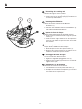
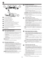
To install bagger com po nents to tractor
02590
1
2
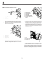
1. Dis charge Chute
2. 3/8 Nut
3. Flat Washer
3
1
2
1. 3/8 Lock nut
2. Flat Wash er
3. Support Tube
3
5
3
1
4
2
1. Support Bracket
2. 3/8 Carriage Bolt
3. 3/8 Lock Nut
4. 3/8 x 63,5mm Hex Bolt
5. 10,3mm (13/32") flat
washer
1. Hook
2. Discharge Chute
3. Back plate slot
2
1
3
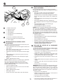
• Remove discharge chute from rear of tractor. Unhook the
two (2) straps and pull chute out and away from tractor.
• Remove the two (2) 3/8 nuts and fl at washers from the
bolts at the tractor back plate.
• Using the nuts and fl at washers removed from tractor
back plate, install the bagger support tube to the back
plate as shown. Tighten securely.
• Install the two upper support brack ets through the back
plate and to the chas sis, using the 10 x 19 mm (3/8"x3/4")
carriage bolts and locknuts sup plied. Tight en se cure ly.
• Assemble both support brackets to the outside of the
baggger support tube using two each 3/8 x 63,5mm hex
bolts13/32" I.D. fl at washers and 3/8 locknuts from parts
bag. Tight en securely.
• Replace discharge chute into rear opening of tractor.
Secure the chute with the two hook straps.
NOTE: The strap hook must go through the discharge chute
only. Do not allow the hook to enter the slot in the tractor
back plate. This will allow the dis charge chute to fl oat with the
mower deck when moving on uneven terrain.
3

25
2
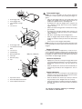
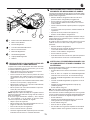
To Assemble Bagger
NOTE: For ease of assembly, you may wish to obtain the
assistance of another person when putting the bagger to-
geth er.
• Holes in front bagger tube are at an angle. Place front
bagger tube against lower bagger tube and check for
proper hole alignment before assembling bolts.
• Assemble front and lower bagger tubes using four (4)
1/4 x 50,8mm carriage bolts and lock nuts supplied.
Tighten se cure ly.
• Slide front and lower bagger tube assembly into the bag-
ger assemby.
• Assemble front and upper bagger tubes using four (4)
1/4 x 50,8mm carraige bolts and lock nuts supplied.
Tighten se cure ly.
• Slip all the vinyl bindings over the bagger tubes
• Slide the bagger dump handle through the hole in the
bagger top, install the clevis pin and secure with retainer
spring.
• Push cap over end of bagger dump handle.
NOTE: For future use, the clevis pin may be removed in order
to use the handle to clear the chute in the event it has become
clogged.
Bagger adjustment
For proper bag function and appearance, it may be nec es -
sary to adjust the bagger assembly. There should be 6mm
(1/4")-9mm (3/8") gap between the bagger top and fender and
the bagger top surface should be even with the top surface
of the fender. To adjust bagger position:
Horizontal adjustment
• Slightly loosen the nuts securing the bagger RH and LH
hor i zon tal adjustment brackets. Loosen only enough so
the brackets keep their position, but allow them to be
moved.
• Move the brackets the amount forward or back ward you
wish the bag assembly to move. Retighten the nuts se-
curely.
Vertical adjustment
• Slightly loosen the nuts securing the vertical adjustment
brackets. Loosen only enough so the brackets keep their
position, but allow them to be moved.
• Move the brackets the amount up or down you wish the
bag assembly to move. Retighten the nuts securely.
• Reinstall the bagger as sem bly and check the bagger to
fender fi t. If necessary, repeat the procedure until proper
fi t is attained.
To convert to bagging, mulching or discharge
See "Sec tion 5" of this manual.
0259
2
02593
2
4
1
3
5
6
2
7
1
4
1. Front bagger tube
2. Lower bagger tube
3. 1/4 x 50,8mm Car riage
Bolts
4. 1/4 Lock nut
1. Front bagger tube
2. 1/4 x 50,8mm Car riage
Bolts
3. 1/4 Lock nut
4. Vinyl Binding
5. Dump handle tube
6. Clevis pin
7. Retainer spring
8. Cap
02329
1
1. Top Surfaces Even
2. Horizontal Adjustment Brack et
3. Vertical Adjustment Brack et
3
6MM (1/4") - 9MM (3/8")
2
3
8

26
2
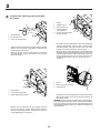
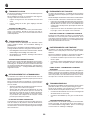
Installation der Aufhängung der Grasfangbox
des Traktors
1. Kontermutter
2. Flache Unterlegscheibe
3. Halterungder Grasfangbox
1. Strebe
2. Tragbolzen 3/8
3. Kontermutter 3/8
4. Sechskantbolzen
3/8 x 63,5mm
5. Flache Unterlegscheibe
10,3mm (13/32)
1. Haken
2. Nut auf der hinteren platte
3. Auswurfkanal
• Nehmen Sie den Auswurfkanal aus dem hinteren Teil des
Traktors. Lösen Sie beide (2) Klammern und ziehen Sie
den Kanal aus dem Traktor.
• Entfernen Sie die zwei (2) 3/8-Zoll-Muttern und fl achen
Unterlegscheiben von den Schrauben an der hinteren
Platte des Traktors.
• Bringen Sie die Halterung der Grasfangbox mit Hilfe
der von der hinteren Platte abgenommenen Muttern
und fl achen Unterlegscheiben an der hinteren Platte an
(siehe Abbildung). Fest anziehen.
• Die beiden oberen Stützwinkel mittels der beigelegten
0.38" [10 mm] dicken und 0.75 Zoll [19 mm] langen
Schloßschrauben und Gegenmuttern durch die Rück-
enplatte am Chassis befestigen. Fest anziehen.
• Montieren Sie nun die beiden Streben an die Außenkante
der Halterung der Grasfangbox mit Hilfe von 3/8 x 63,5-
mm-Sechskantschrauben, fl achen Unterlegscheiben mit
einem Innendurchmesser von 13/32 Zoll (1,03 cm) und
3/8-Zoll-Kontermuttern (0,95 cm), wie gezeigt. Fest
anziehen.
• Schieben Sie nun den Auswurfkanal wieder in die hintere
Öffnung des Traktors. Sichern Sie den Auswurfkanal mit
den beiden Haken.
HINWEIS: Die Haken dürfen nur durch den Auswurfkanal ge-
führt werden. Der Haken darf nicht in die Nut auf der hinteren
Platte des Traktors gesteckt werden. Andernfalls bewegt sich
der Auswurfkanal beim Mähen von unebenem Gelände mit
dem Mäherdeck.
1. Auswurfkanal
2. Kontermutter 3/8
3. Flache unterlegscheibe
02306
02277
02330
02590
1
2
3
1
2
3
5
3
1
4
2
2
1
3
3
Page is loading ...
Page is loading ...
Page is loading ...
Page is loading ...
Page is loading ...
Page is loading ...
Page is loading ...
Page is loading ...
Page is loading ...

36
2
A
A
1
3
4
2
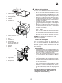
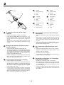
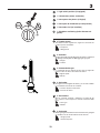
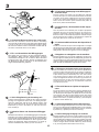
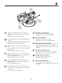
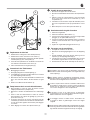
1. Handle
2. Retainer Spring
3. Pin
4. Plug
1. Handgriff
2. Fixierfeder
3. Stift
4. Stöpsel
1. Poignée de l'insert
2. Epingle
3. Axe de fi xation
4. Tête de l'insert
1. Impugnatura
2. Coppiglia
3. Perno
4. Kit Mulch ing
1. Hendel
2. Sluitveer
3. Pen
4. Plug
1. Mango
2. Resorte fi jador
3. Clavija
4. Tapon o tapa
To assemble and install mulcher plug (if
equipped)
• Remove spring retainer and pin from handle.
• Insert plug into handle. Make sure that the letter "A" on
both the plug and handle are on the same side and that
they can both be seen from the top when laying on the
ground.
• Secure with pin and retainer spring provided. For in-
stal la tion see "To Convert Mower" in Section 5 of this
manual.
Montage und Installation des Mulcheinsatzes
(sofern vorhanden)
• Entfernen Sie den Splintstift und Stift vom Griff.
• Stecken Sie den Stöpsel in den Handgriff. Versichern Sie
sich, daß die Markierung „A“ sich sowohl beim Stöpsel,
als auch beim Handgriff auf der gleichen Seite befi ndet.
Beide Markierungen müssen von oben sichtbar sein,
wenn das Teil auf dem Boden liegt.
• Fixieren Sie beide Teile mit dem Stift und der Fixierfeder.
Mehr zum Einsatz des Mulcheinsatzes erfahren Sie in
Abschnitt 5 der Betriebsanweisung.
Pour assembler l'insert broyeur (si équipé)
• Retirer l'épingle et l'axe de fi xation.
• Insérer la tête de l'insert dans la poignée. Vérifi er que
les lettres A et B, moulées sur chacune des parties, se
trouvent bien du même côté sur la tête et sur la poignée
de l'insert, et si elles sont visibles du dessus lorsque
l'insert est posé sur le sol.
• Insérer ensuite l'axe de fi xation à travers les trous prévus
à cet effet dans les deux parties de l'insert et le bloquer
à l'aide de l'épingle. Pour mettre en place l'insert (et pour
passer de la fonction broyage à la fonction éjection ar-
rière), se reporter au chapitre 5 de ce manuel.
Per I'installazione del Kit Mulching (se instal-
lato):
• Rimuovere dall'impugnatura il fermo a molla e il perno.
• Agganciare il Kit all'apposita maniglia. Verifi care che le
due lettere "A" siano allineate.
• Fissare il perno con la coppiglia.
Per l'installazione vedere "Adattamento del trattorino" al
Capitolo 5 del presente Manuale.
Het monteren en installeren van de mulchplug
(indien hiermee uitgerust)
• Verwijder de veerborg en de pin van de hendel.
• Steek de plug in de hendel. Zorg ervoor dat de letter A
op zowel de plug als de hendel aan dezelfde kant staan
en dat ze beide vanaf de bovenkant zichtbaar zijn als ze
op de grond liggen.
• Zet vast met de meegeleverde pen en de sluitveer. Voor
installatie zie "De maaier ombouwen" in Hoofdstuk 5 van
dit handboek.
Para ensamblar y montar la tapa mulching (si
está provisto)
• Remover el retén del muelle y el pasador de la enpuña-
dura.
• Meta la tapa en el mango. averigüe de que las letras "A"
sobre la tapa y el mango sean de un mismo lado y de
que se vean las dos encima en posición hor i zon tal sobre
el suelo.
• Fije con los previstos para este propósito clafi ja y resorte
fi jador. Para la instalación vea "Ajuste de la segadora"
en Parte 5 del manual presente.

37
3. Functional description. 3. Funktionsbeschreibung.
3. Description du fonctionnement.
3. Descripción del funcionamiento. 3. Funzionamento.
3. Beschrijving van functies
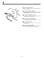
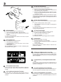
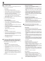
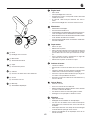
Positioning of controls
1. Light Switch Position.
2. Throttle control.
3. Brake and clutch pedal.
4. Motion Control Lever.
5. Connection/disconnection of the cutting unit.
6. Quick lifting/lower of the cutting unit.
7. Ignition lock.
8. Parking Brake.
9. Free-wheel control lever.
10. Choke Control.
Anordnung der Bedienungseinrichtungen
1. Lichtschalter.
2. Gashebel.
3. Brems- und Kupplungspedal.
4. Ein- und Ausschalten des Antriebes.
5. Ein- und Ausschalten des Mähaggregats.
6. Schnelles Heben und Senken des Mähaggregats.
7. Zündschloß.
8. Feststellbremse.
9. Ein-und Ausschalten des Freilaufes.
10. Kalstartregler.
6
1
7
3
2
5
8
4
9
10

38
3
6
1
7
3
2
5
8
4
9
Emplacement des commandes
1. Interrupteur de commande des phares.
2. Commande des gaz (Accélérateur).
3. Pédale d'embrayage et de frein.
4. Levier de commande dela transmission hydrostatique.
5. Embrayage/débrayage du carter de coupe.
6. Relevage et abaissement du carter de coupe.
7. Clé de contact/démarrage.
8. Frein de parking.
9. Blocage/déblocage de la roue libre.
10. Starter.
Ubicación de los mandosè
1. Interruptor de alumbrado.
2. Acelerador.
3. Pedal de freno y de embrague.
4. Acoplamiento/desacoplamiento de la tansmisión.
5. Acoplamiento y desacoplamiento del equipo de corte.
6. Elevación/descenso rápidos del equipo de corte.
7. Cerradura de encendido.
8. Freno de estacionamiento.
9. Acoplamiento y desacoplamiento de rueda libre.
10. Estrangulador.
Comandi
1. Interruttore luci.
2. Acceleratore.
3. Pedale freno/frizione.
4. Leva del cambio.
5. Inserimento/disinserimento del dispositivo di taglio.
6. Sollevamento/abbassamento del tagliaerba.
7. Chiave di accensione.
8. Freno di parcheggio.
9. Inserimento/disinserimento ruote.
10. Choke.
De plaats van de bedieningsorganen
1. Schakelaar verlichting.
2. Gashendel.
3. Rem- en koppelingspedaal.
4. Aan-/uitschakeling van aandrijving.
5. Koppelen en onkoppeleen van de maaikast.
6. Snelle verhoging/verlaging van maaikast.
7. Stuurslot/contact.
8. Parkeerrem.
9. Aan-en uitschakeling van vrijwiel.
10.Chokeregelaar.
10

39
3
01355
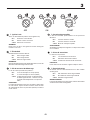
2. Throttle control
The throttle control regulates the engine revs and thus the
rotation speed of the blades.
= Full speed
= Idling speed
2. Gashebel
Mit dem Gashebel wird die Drehzahl des Motors und damit
die Drehgeschwindigkeit des Mähaggregats geregelt.
= Vollgas
= Leerlauf
2. Commande des gaz
La commande des gaz permet de faire varier le régime du
moteur et donc la vitesse de rotation des lames.
= Régime rapide
= Ralenti
2. Acelerador
Se regula con él el régimen del motor y, por lo tanto, también
la velocidad de rotación de las cuchillas.
= Posición de plena aceleración.
= Posición de ralenti
2. Acceleratore
Questo comando aumenta o diminuisce il regime di giri
del motore e di consequenza la velocità di rotazione delle
lame.
= Pieno gas
= Minimo
2. Gashendel
Met de gasregelaar wordt het toerental van de motor geregeld
en daardoor ook de rotatiesnelheid van de messen.
= Volgas-positie
= Stationair-positie
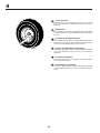
1. Light switch position (if equipped)
1. Lichtschalter (sofern vorhanden)
1. Interrupteur des phares (si équipé)
1. Interruptor de alumbrado (si está provisto)
1. Interruttore luci (se installato)
1. Schakelaar verlichting (indien hiermee uit-
gerust)
Page is loading ...
Page is loading ...
Page is loading ...
Page is loading ...
Page is loading ...
Page is loading ...
Page is loading ...
Page is loading ...
Page is loading ...
Page is loading ...
Page is loading ...
Page is loading ...
Page is loading ...
Page is loading ...
Page is loading ...
Page is loading ...
Page is loading ...
Page is loading ...
Page is loading ...
Page is loading ...
Page is loading ...
Page is loading ...
Page is loading ...
Page is loading ...
Page is loading ...
Page is loading ...
Page is loading ...
Page is loading ...
Page is loading ...
Page is loading ...
Page is loading ...
Page is loading ...
Page is loading ...
Page is loading ...
Page is loading ...
Page is loading ...
Page is loading ...
Page is loading ...
Page is loading ...
Page is loading ...
Page is loading ...
Page is loading ...
Page is loading ...
Page is loading ...
Page is loading ...
Page is loading ...
Page is loading ...
Page is loading ...
Page is loading ...
-
 1
1
-
 2
2
-
 3
3
-
 4
4
-
 5
5
-
 6
6
-
 7
7
-
 8
8
-
 9
9
-
 10
10
-
 11
11
-
 12
12
-
 13
13
-
 14
14
-
 15
15
-
 16
16
-
 17
17
-
 18
18
-
 19
19
-
 20
20
-
 21
21
-
 22
22
-
 23
23
-
 24
24
-
 25
25
-
 26
26
-
 27
27
-
 28
28
-
 29
29
-
 30
30
-
 31
31
-
 32
32
-
 33
33
-
 34
34
-
 35
35
-
 36
36
-
 37
37
-
 38
38
-
 39
39
-
 40
40
-
 41
41
-
 42
42
-
 43
43
-
 44
44
-
 45
45
-
 46
46
-
 47
47
-
 48
48
-
 49
49
-
 50
50
-
 51
51
-
 52
52
-
 53
53
-
 54
54
-
 55
55
-
 56
56
-
 57
57
-
 58
58
-
 59
59
-
 60
60
-
 61
61
-
 62
62
-
 63
63
-
 64
64
-
 65
65
-
 66
66
-
 67
67
-
 68
68
-
 69
69
-
 70
70
-
 71
71
-
 72
72
-
 73
73
-
 74
74
-
 75
75
-
 76
76
-
 77
77
-
 78
78
-
 79
79
-
 80
80
-
 81
81
-
 82
82
-
 83
83
-
 84
84
-
 85
85
-
 86
86
-
 87
87
-
 88
88


Aeg-Electrolux 135H92RB Owner's manual
- Category
- Lawnmowers
- Type
- Owner's manual
Ask a question and I''ll find the answer in the document
Finding information in a document is now easier with AI