Note: Please consider the powdercoated parts can differ slightly in colour and colour effects though they are elaborated in high quality.
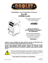
Nr. Art.Nr. Description
1 L01441 Pressure bracket
2 L01447 Ash drawer
3 *1 B15621 Key display
3 *2 B16574 Touch-display plug-in
4 Z34176 Reservoir rear gray
Z34193 Reservoir rear black
5 Z34194 Container lid grey (till serial no.
1305473)
Z34195 Container lid black (till serial no.
1305473)
Z35609 Container lid grey (from serial no.
1305474)
Z35608 Container lid black (from serial no.
1305474)
6 Z34141 Cover panel, bottom grey
Z34196 Cover panel, bottom black
7 N103693 Flat seal black 8x2
8 Z34197 Cover panel grey (till serial no.
1305473)
Z34198 Cover panel black (till serial no.
1305473)
Z35611 Cover panel grey (from serial no.
1305474)
Z35610 Cover panel black (from serial no.
1305474)
9 N110461 Double ball catch
10 N111730 Grommet
11 Z34135 Comb. chamber cover grey
Z33788 Comb. chamber cover black
12 Z34084 Combustion chamber door
B16324 Combustion chamber door assy
Z34235 Combustion chamber door
metallic
B16380 Combustion chamber door
metallic assy
13 Z32866 Combustion chamber door glass
14 Z32867 Front stone soapstone
Z33187 Sandstone front
Z36819 Front stone white
15 *3 L00838 Front holder
L01921 Front holder
16 B16053 Sensor tube
17 N111581 Induced draft fan motor
18 B15807 Hinge BA1
19 L00475 Glass holder
20 N111731 Container seal
21 Z34132 Cast rear panel, top, metallic grey
Z33786 Cast rear panel, top black
22 Z34131 Cast rear panel bottom metallic
grey
Z33785 Cast rear panel bottom black
23 *1 B15856 Motherboard C2 (key display)
23 *2 B16561 Mainboard USB11
24 *4 B17166 Ceramic ignition
25 Z33791 Firebrick lining rear left
26 Z33792 Firebrick lining rear right
27 Z33789
Firebrick lining front left
28 Z33790 Firebrick lining front right
29 Z11915 Lock ring conveyer screw
30 B15506 Convection ns metallic grey
B15646 Convection ns black
31 Z34137 Air blade
32 N111732 Magnetic switch top part
33 N111733 Solenoid switch bottom part
34 Z32345 Fire trough
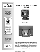
Nr. Art.Nr. Description
35 Z33692 Fire trough holder
36 B16320 Cleaning opening metallic
B16352 Cleaning opening black
37 Z26051 Rest spring
38 N111280 Sealing cord Ø8mm
39 N112551 Round sealing strip grey D11
40 N111825 Door contact switch
41 L01777 Rear wall grey
L01812 Rear wall black
42 N103066 Round sealing strip black D06
43 B16155 Induced draft fan housing
B15913 Induced draft fan assy
44 N112017 Key
45 L01448 Hinge
46 L01772 Hinge left
L02542 Hinge left (from serial no.
1305474)
47 L01773 Hinge right
L02543 Hinge right (from serial no.
1305474)
48 Z30494 Hinge shaft
Z34854 Hinge shaft
49 L01813 Hinge holder (till serial no.
1305473)
L02498 Hinge holder (from serial no.
1305474)
50 N110461 Double ball catch
51 B12301 Auger
52 N112030 Screw motor, stepless
53 N100483 Hexagonal nut M10
54 N107887 Fuse holder
55 Z34138 Cover panel left metallic grey
Z34200 Cover panel left black
56 Z34139 Cover panel right metallic grey
Z34199 Cover panel right black
57 *5 Z35182 Friction bearing Di16
58 Z35183 Friction bearing Di10
59 N111586 Safety temperature limiter
60 B16328 Stone holder left/right
62 L01781 Side casing panel back left grey
L01814 Side casing panel back left black
63 L01816 Side casing connection left grey
L01815 Side casing connection left black
64 *1 L01780 Side casing back right grey
64 *2 B17472 Side casing back right grey for
touch-display
64 *1 L01817 Side casing back right black
64 *2 B17471 Side casing back right black for
touch-display
65 Z32870 Side casing soapstone left
Z34201 Side casing sandstone left
Z36818 Side casing stone white left
66 Z32869 Side casing soapstone right
Z34202 Side casing sandstone right
Z36817 Side casing stone white right
67 B16114 Temperature sensor
68 L01998 Closure ap
L00427 Closure ap black
69 L01449 Lock tongue
70 Z33794 Locking bolt
71 L01450 Closure plate
72 N100485 Round sealing strip black D12
73 LB00757 Bafe plate
B18544 Bafe plate support
Nr. Art.Nr. Description
74 B16030 Additional motherboard for motor,
incl. cable
*1 B16058 Wiring harness for key display
*2 B17364 Wiring harness for touch-display
*1 Z33136 Cable for Key display
*2 Z35018
Cable for touch-screen 1,25 m
L00797 Motor plate
N111604 Fuse 2,5 A
E15471 Sealing kit
Z34841 Cable for additional motherboard
*1 till serial number 1346067
*2 from serial number 1346068
*3 till serial number 276572
*4 requires 2,5A fuse N111604 till
serial number 1346068
*5 up to serial number 1331613 the
motor plate (L00797) must be
supplied as a spare part when
replacing the plastic bearing Di16
(Z35182).
6
Spare part overview article numbers