Trotec MD 05-30 Operating instructions
- Category
- Mobile air conditioners
- Type
- Operating instructions
This manual is also suitable for

DE
EN
FR
IT
NL
ES
PT
TROTEC
®
GmbH & Co. KG • Grebbener Straße 7 • D-52525 Heinsberg
Tel.: +49 2452 962-400 • Fax: +49 2452 962-200
www.trotec.com • E-Mail: [email protected]
TRT-BA-TTK 100 E-TC-003-INT
Bedienungsanleitung – Luftentfeuchter TTK 100 E .............. A - 1
Operating Manual – Dehumidifier TTK 100 E ........................ B - 1
Manuel d'utilisation – Déshumidificateur TTK 100 E ............ C - 1
Istruzioni per l'uso – Deumidificatore TTK 100 E .................. D - 1
Bedieningshandleiding – Luchtontvochtiger TTK 100 E....... E - 1
Manual de instrucciones – Deshumidificador TTK 100 E..... F - 1
Manual de instruções – Desumidificador TTK 100 E ............ G - 1
TTK 100 E
Page is loading ...
Page is loading ...
Page is loading ...
Page is loading ...
Page is loading ...
Page is loading ...
Page is loading ...
Page is loading ...
Page is loading ...
Page is loading ...
Page is loading ...
Page is loading ...

A - 13 Bedienungsanleitung – Luftentfeuchter TTK 100 E DE
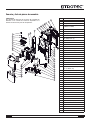
Ersatzteilübersicht und Ersatzteilliste
ij
IJ
ĵ
Ĵ
ķġ
Ķ
ĺġ
Ĺ
IJı
IJIJ
ĴIJ
Ĵı
ijķ
ijĵ
IJĺ
ijIJ
ijĸ
Ĵķ
Ĵĸ
ĵIJ
ĵı
Ĵĺ
ĴĶ
ijij
IJĸ
IJĵ
IJĴ
ijĺ
ĴĴ
Ĵĵ
ĴĹ
IJĶ
IJķ
ijĴ
ijĶ
Ĵij
IJĹ
ijı
ĸ
IJij
ĵij
ijĹ
Hinweis!
Die Positionsnummern der Ersatzteile unterscheiden sich
von den in der Bedienungsanleitung verwendeten Positions-
nummern der Bauteile.
Nr. Ersatzteil
1 Base Pan
2 Turning Wheel Assembly
3 Compressor Assembly
(35D042-A1-ABDA)
4 Rubber Attenuator
5 Suction Pipe
6 Discharge Pipe
7Plate
8 Capacitor (10 uF / 450 V)
(For Compressor (3))
9 Fix Metal
10 Fixture 1
11 Micro Switch
12 Drainage Pan
13 Evaporator Assembly (2R11S17FPI)
14 Condenser Assembly (2R11S21FPI)
15 Y Tube
16 Capillary Tube
17 Fixture 2
18 Fan Motor (LS-16D2-01)
19 Fan Casing
20 Blower Wheel
21 Screen
22 Capacitor (1.5 uF / 450 V)
(For Fan Motor (18))
23 Power Supply Cord Complete
24 Fixture 3
25 Cover
26 Control Board
27 Pc Board
28 Sensor 1
29 Fixture 4
30 Fix Metal
31 Side Plate R
32 Side Plate L
33 Pear Panel
34 Handle
35 Front Panel
36 Control Plate
37 Control Panel
38 Intake Grille (Complete)
39 Tank Lid
40 Float
41 Drain Bucket
42 Sensor 2
43 Cover
Page is loading ...

B - 1 Operating Manual – Dehumidifier TTK 100 E EN
Notes regarding the operating manual............ B - 01
Information about the device .......................... B - 02
Safety............................................................. B - 04
Transport......................................................... B - 05
Operation ........................................................B - 05
Errors and faults.............................................. B - 09
Maintenance................................................... B - 10
Disposal ......................................................... B - 14
Declaration of conformity................................. B - 14
Symbols
Hazardous electric current!
Warns about hazards from electric
current which can lead to injuries or even
death.
Danger!
Warns of a hazard which can lead to
personal injury.
Caution!
Warns of a hazard which can lead to
damage to property.
The current version of the operating manual can be
found at: www.trotec.de
Legal notice
This release replaces all previous releases. No part of
this publication may be reproduced without written
permission. The same applies for electronically
processing, duplicating or spreading the publication.
Subject to technical changes. All rights reserved.
Trademarks are used without guarantee that they may
be used freely and primarily following the spelling of
the manufacturer. The product names used are
registered and should be treated appropriately. The
delivered product may vary from product images. This
document was produced with all due care. We accept
no liability whatsoever for mistakes or omissions.
©TROTEC
®
Table of contents
Notes regarding the operating manual

EN Operating Manual – Dehumidifier TTK 100 E B - 2
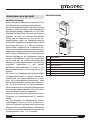
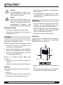
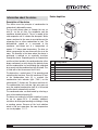
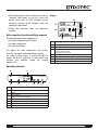
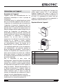
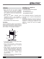
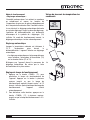
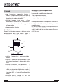
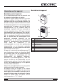
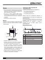
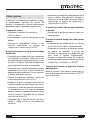
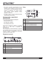
Description of the device
This device uses the principle of condensation to
automatically dehumidify rooms.
The fan sucks damp room air through the rear air
inlet (5), via the air filter, the evaporator and the
condenser located behind it. The air is cooled at the
cold evaporator until it is below the dew point. Water
vapour contained in the room air precipitates on the
evaporator fins as either condensation or frost. The
dehumidified, cooled air is rewarmed at the
condenser and blown out at a temperature of
approx. 5 °C above room temperature. The drier air
which is prepared in this way mixes with the air in the
room. The humidity in the room where the device is
positioned is reduced as air constantly circulates
through the device. Depending on the air temperature
and the relative humidity, the condensed water either
drops continuously or only during the defrost phase
into the condensation tray and through the integrated
drain nozzle into the condensation tank (6) below. This
is fitted with a float to measure the fill level.
The device has a control panel (7) for operating and
controlling the functions. Once the maximum fill level
of the condensation tank (6) is reached, the
condensation tank indicator light ("FULL") on the
control panel (7) flashes red. The device switches off.
The condensation tank indicator light only goes out
once the emptied condensation tank (6) is reinserted
and the device automatically restarts.
The condensed water can be diverted by attaching a
hose at the condensation plug (3).
The device can reduce the relative humidity of a room
by up to approx. 30 %. It provides additional
assistance for drying wet washing or clothing in living
or working spaces. Because of the heat radiation
which is tied up in operation, the room temperature
can rise by approx. 1-4 °C.
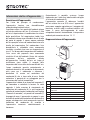
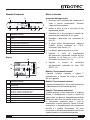
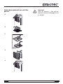
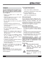
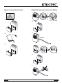
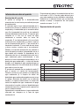
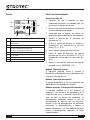
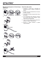
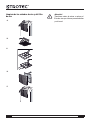
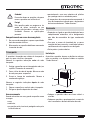
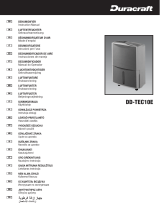
Device depiction
Information about the device
No. Operating element
1 air outlet
2 carry handle
3 cover for attaching a hose to the condensation plug
4 wheels
5 air inlet
6 condensation tank
7 control panel
7
1
2
3
5
4
6

B - 3 Operating Manual – Dehumidifier TTK 100 E EN
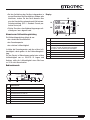
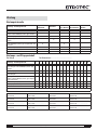
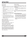
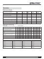
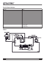
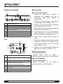
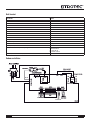
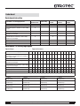
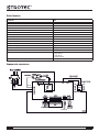
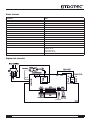
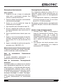
Technical data
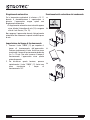
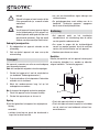
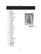
Circuit diagram
Parameters Values
Model TTK 100 E
Dehumidifying capacity, max. 30 l / 24 h
Operating temperature 5-35 °C
Working range for relative humidity 40-100 %
Volume of airflow, max. 200 m³/h
Electric connection 230 V / 50 Hz
Power consumption, max. 630 W
Fuse (home) 4.15 A
Condensation tank 5.5 l
Refrigerant R410A
Amount of refrigerant 180 g
Weight 15.2 kg
Dimensions (HxDxW) 612 x 290 x 390 mm
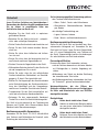
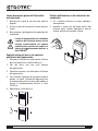
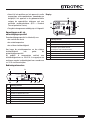
Minimum distance from walls of other objects A: Above: 50 cm
B: Behind: 20 cm
C: Side: 20 cm
D: Front: 20 cm
Sound pressure level LpA (1 m; complies with DIN 45635-01-KL3) 46 dB(A)
HI LO
ORANGE
YELLOW
F/MOTOR
CAPACITOR
WHITE
BLACK
NO
COM.
BLUE
CONTROL BOARD
H.sensor
T.sensor
COM.

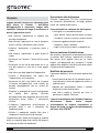
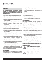
EN Operating Manual – Dehumidifier TTK 100 E B - 4
Read this manual carefully before starting or
using the device. Store the manual near the device
or its site of use!
• Do not use the device in potentially explosive
rooms.
• Do not use the device in atmospheres containing
oil, sulphur, chlorine or salt.
• Set the device in an upright and stable position.
• Do not expose the device to directly squirting
water.
• Ensure that the air inlet and outlet are not
obstructed.
• Ensure that the side of the device where the air
inlet is found is kept free of dirt and loose objects.
• Never insert objects into the device.
• Do not cover or transport the device during
operation.
• Ensure that all electric cables outside of the device
are protected from damage (e.g. from animals).
• Only use extensions to the electric cable which are
appropriate to the device power consumption, the
length of its cable and its use. Avoid electrical
overload.
• Only transport the device in an upright position
with an emptied condensation tank.
• Dispose of the collected condensation. Do not
drink it. There is a risk of infection!
The device is not suitable for drying rooms and areas
after water damages from burst pipes or flooding.
Intended use
Use the device TTK 100 E only for drying and
dehumidifying room air, while adhering to and
following the technical data.
Intended use encapsulates:
• drying and dehumidifying:
– living rooms, bedrooms, bathrooms or
basements
– laundries, holiday homes, camper vans, boats
• maintaining the dryness of:
– store rooms, archives, laboratories
– bathrooms, wash rooms and changing rooms
Improper use
Do not place the device on damp or flooded ground.
Do not use the device outdoors. Do not lay any
objects, e.g. wet clothing, on the device for drying.
Any unauthorised changes, modifications or
alterations to the device are forbidden.
Personnel qualifications
People who use this device must:
• be aware of the dangers that occur when working
with electric devices in damp areas.
• take measures to protect themselves from direct
contact with live parts.
• have read and understood the operating manual,
especially the "Security" chapter.
Maintenance tasks which require the housing to
be opened must only be carried out by specialist
companies for cooling and air-conditioning or by
TROTEC
®
.
Residual risks
Hazardous electric current!
Work on the electrical components must
only be carried out by an authorised
specialist company!
Hazardous electric current!
Before any work on the device, remove
the mains plug from the mains socket!
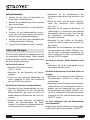
Safety

B - 5 Operating Manual – Dehumidifier TTK 100 E EN
Caution!
To avoid damages to the device, never
operate the device without an air filter
inserted!
Danger!
Dangers can occur at the device when it
is used by untrained people in an
unprofessional or improper way! Observe
the personnel qualifications!
Behaviour in the event of an emergency
1. Disconnect the device from the mains power in an
emergency.
2. Do not reconnect a defective device to the mains
power.
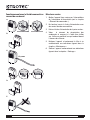
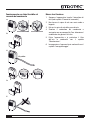
To make the device easier to transport, it is fitted with
wheels and a carry handle.
Before transporting the device, proceed as follows:
1. Switch off the device at the mains switch
(see chapter "Operating elements").
2. Remove the mains plug from the mains socket.
Do not use the power cable to drag the device!
3. Empty the condensation tank. Check for dripping
condensation.
After transporting the device, proceed as follows:
1. Set the device in an upright position after
transport.
2. Wait one hour before switching the device on!
Storage
When out of use, store the device as follows:
•dry,
• with a roof overhead,
• in an upright position where it is protected from
dust and direct sunlight,
• with a plastic cover to protect it from invasive dust,
if necessary.
• The storage temperature is the same as the range
given for the operating temperature in the chapter
"Technical Data".
• After being switched on, the device operates fully
automatically until the float indicates that the
condensation tank is full and the device switches
itself off.
• So that the built in sensor can correctly detect the
humidity, the fan continues to operate until the
device is switched off.
• Avoid open doors and windows.
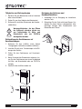
Positioning
When positioning the device, observe the minimum
distance from walls of other objects as described in
chapter "Technical Data".
• Set the device in a level and stable position.
• If possible, set the device in the middle of a room
and keep it away from sources of heat.
Transport
Operation
C
C
A
B
D

EN Operating Manual – Dehumidifier TTK 100 E B - 6
• When positioning the device in wet areas such as
laundries, bath rooms or the like, secure the
device locally with an RCD (Residual Current
protective Device) which complies with the
appropriate regulations.
• Ensure that extension cords are completely
unrolled.
Notes regarding the dehumidifying capacity
The dehumidifying capacity depends on:
• the spatial composition of the room
• the room temperature
• the relative humidity
The higher the room temperature and relative
humidity, the higher the dehumidifying capacity.
For using in living rooms, a relative humidity of
approx. 50-60 % is sufficient. In store rooms and
archives, the humidity should not exceed
approx.50%.
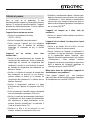
Operating elements
Display
No. Operating element
8 Condensation tank full indicator light (red)
9Display
10 Mains switch:
Switches the device on and off.
11 "TIMER" button
12 Arrow button down
13 Arrow button up
14 "FAN SPEED" button
TANK FULL
ROOM HUMIDITY
88
88
%RH
°C
STOP
(%)
80
70
60
50
40
30
ROOM TEMP
SETTING MODE
°C
10
8
11 12 13 14
9
No. Operating element
15 Condensation tank full or not correctly inserted.
16 Desired level of humidity (30-80 %)
17 Fan speed:
One drop: low fan speed
Two drops: high fan speed
18 "Defrost" symbol
19 "Timer" symbol with operating time (1-12 hours)
20 Room temperature
21 Current humidity
88
88
%RH
°C
STOP
(%)
80
70
60
50
40
30
°C
16
19
20
21
1718
15

B - 7 Operating Manual – Dehumidifier TTK 100 E EN
Start procedure
Switch device on
1. Ensure that the condensation tank is empty and
inserted correctly. Otherwise, the device will not
operate!
2. Insert the mains plug into a properly secured
mains power socket.
3. Check whether the condensation tank indicator
light (8) is out.
4. Switch on the device at the mains switch (10).
5. The first time that you use the device, use the
arrow button (12) to set the desired level of
humidity to < 30 %.
6. Let the device run for approx. one hour.
7. Use the arrow buttons (12 and 13) to adjust the
desired level of humidity to between 30 and 80 %.
8. Regulate the device fan speed by pressing the
"FAN SPEED" button (14).
"Normal" operation mode
The built in humidistat switches the defrost back on or
off depending on the humidity.
"Continuous" operation mode
The device dehumidifies the air constantly and
regardless of the amount of humidity in the air.
"Automatic defrost" operation mode
Upon cooling, the moisture in the room air condenses
and covers the evaporator fins with ice, regardless of
the air temperature and the relative humidity.
Automatic defrost switches on the defrost cycle when
necessary. During the defrost phase, dehumidifying is
temporarily paused and the "defrost" symbol (18) is
shown. Automatic defrost is activated automatically in
"Normal" operation mode.
Automatic defrost
If the room temperature is below 15 °C, the
evaporator becomes covered in frost while
dehumidifying. The device then carries out an
automatic defrost.
• The automatic defrost is interrupted as soon as the
mains switch (10) or the arrow buttons (12 or 13)
are pressed.
Do not turn off the device during the automatic
defrost. Do not remove the mains plug from the mains
socket.
Adjusting the operating time
1. Press the "TIMER" button (11) to set the operating
time of the device. Keep pressing the button until
the desired operating time is displayed (between
1 and 12 hours). After the operating time has
passed, the device automatically switches off.
2. To switch this function off, press the "TIMER"
button (11) again until the "00" operating time is
displayed.

EN Operating Manual – Dehumidifier TTK 100 E B - 8
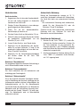
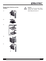
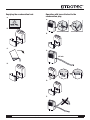
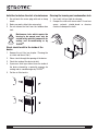
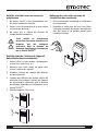
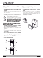
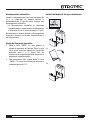
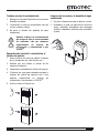
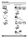
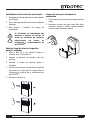
Emptying the condensation tank Operation with hose attached to the
condensation plug
A.
B.
C.
D.
A.
B.
1/2 inch
C.
D.
E.

B - 9 Operating Manual – Dehumidifier TTK 100 E EN
Shut down procedure
1. Switch off the device at the mains switch (see
chapter "Operating elements").
2. Do not touch the mains plug with wet or damp
hands.
3. Remove the mains plug from the mains socket.
4. Empty the condensation tank and wipe it dry with
a clean cloth. Check for dripping condensation.
5. Clean the device, and especially the air filter,
according to chapter "Maintenance".
6. Store the device according to chapter "Storage".
The accurate functionality of the device was tested
during production a number of times. However, if
functionality faults do occur, then check the device
according to the following list.
The device does not start:
• Check the mains power
(230 V/1~/50 Hz).
• Check the mains plug for damages.
• Have the electrics checked by a specialist
company for cooling and air-conditioning or by
TROTEC
®
.
The device runs but forms no condensation:
• Check the condensation tank is positioned
correctly. Check the fill level of the condensation
tank and empty it if necessary. The condensation
tank indicator light must not light up.
• Check the float in the condensation tank for
damages. If necessary, clean the float and
condensation tank. The float must be able to move
freely.
• Check the room temperature. The working range
of the device is between 5 °C and 35 °C.
• Ensure that the relative humidity complies with the
technical data (min. 40 %).
• Check the set operation mode. The humidity in the
room must be above the selected range. If
necessary, reduce the desired level of humidity by
using the arrow button (12).
• Check the air filter is not dirty. If necessary, clean
or replace the air filter.
• From the outside, check the condenser is not dirty
(see chapter "Maintenance"). If your condenser is
dirty, have it cleaned by a specialist company for
cooling and air-conditioning or by TROTEC
®
.
The device is loud or vibrates; condensation leaks:
• Check whether the device is standing upright and
on an even surface.
The device gets very warm, is loud or is losing
performance:
• Check the air inlets and air filter are not dirty.
Remove external dirt.
• Check the inside of the device and especially the
fan, the fan housing, the evaporator and the
condenser for external dirt (see chapter
"Maintenance"). If the inside of the device is dirty,
have it cleaned by a specialist company for cooling
and air-conditioning or by TROTEC
®
.
Does your device still not operate correctly after
these checks?
Bring the device to a specialist company for cooling
and air-conditioning or to TROTEC
®
for repairs.
Errors and faults

EN Operating Manual – Dehumidifier TTK 100 E B - 10
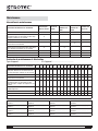
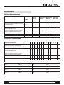
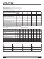
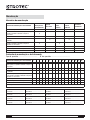
Maintenance intervals
Maintenance and care log
Device type: ........................................ Device number: ........................................
Maintenance
Maintenance and care interval
before every
start
when
necessary
at least every
2 weeks
at least every
4 weeks
at least
annually
empty condensation tank X
check air inlets and outlets for dirt and foreign
objects and clean if necessary
X
clean housing X X
visually check whether the inside of the device is
dirty
XX
check air inlet grid and air filter for dirt and
foreign objects and clean or replace if necessary
XX
check for damages X
check attachment screws X X
carry out a test run X
Maintenance and care interval 12345678910111213141516
check air inlets and outlets for dirt and foreign
objects and clean if necessary
clean housing
visually check whether the inside of the device
is dirty
check air inlet grid and air filter for dirt and
foreign objects and clean or replace if
necessary
check for damages
check attachment screws
carry out a test run
Remarks:
1. Date: ..................................
Signature:...............................
2. Date: ..................................
Signature:...............................
3. Date: ..................................
Signature:...............................
4. Date: ..................................
Signature:...............................
5. Date: ..................................
Signature:...............................
6. Date: ..................................
Signature:...............................
7. Date: ..................................
Signature:...............................
8. Date: ..................................
Signature:...............................
9. Date: ..................................
Signature:...............................
10. Date: ................................
Signature:...............................
11. Date: ................................
Signature:...............................
12. Date: ................................
Signature:...............................
13. Date: ................................
Signature:...............................
14. Date: ................................
Signature:...............................
15. Date: ................................
Signature:...............................
16. Date: ................................
Signature:...............................

B - 11 Operating Manual – Dehumidifier TTK 100 E EN
Activities for before the start of maintenance
1. Do not touch the mains plug with wet or damp
hands.
2. Before any work, detach the mains plug!
3. Do not remove the float from the condensation
tank.
Maintenance tasks which require the
housing to be opened must only be
carried out by specialist companies for
cooling and air-conditioning or by
TROTEC
®
.
Visual check for dirt in the inside of the
device
1. Remove the air filter (see chapter "Cleaning the
air inlets and the air filter").
2. Shine a torch through the opening of the device.
3. Check the inside of the device for dirt.
4. If you see a thick layer of dust, have the inside of
the device cleaned by a specialist company for
cooling and air-conditioning or by TROTEC
®
.
5. Put the air filter back in.
Cleaning the housing and condensation tank
1. Use a soft, lint-free cloth for cleaning.
2. Dampen the cloth with clean water. Do not use
sprays, solvents, alcohol-based or abrasive
cleaners to dampen the cloth.

EN Operating Manual – Dehumidifier TTK 100 E B - 12
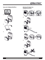
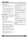
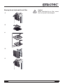
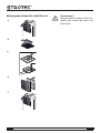
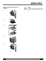
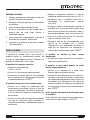
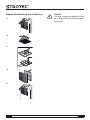
Cleaning the air inlets and the air filter
Caution!
Before reinserting the air filter, ensure
that it is dry and is not damaged!
C.
D.
A.
B.
E.

B - 13 Operating Manual – Dehumidifier TTK 100 E EN
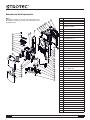
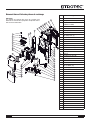
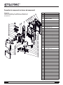
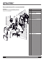
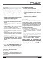
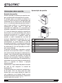
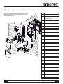
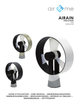
Overview and list of spare parts
ij
IJ
ĵ
Ĵ
ķġ
Ķ
ĺġ
Ĺ
IJı
IJIJ
ĴIJ
Ĵı
ijķ
ijĵ
IJĺ
ijIJ
ijĸ
Ĵķ
Ĵĸ
ĵIJ
ĵı
Ĵĺ
ĴĶ
ijij
IJĸ
IJĵ
IJĴ
ijĺ
ĴĴ
Ĵĵ
ĴĹ
IJĶ
IJķ
ijĴ
ijĶ
Ĵij
IJĹ
ijı
ĸ
IJij
ĵij
ijĹ
Note!
The position numbers of the spare parts differ from those
describing the positions of other parts mentioned in this
operating manual.
No. Spare part
1 Base Pan
2 Turning Wheel Assembly
3 Compressor Assembly
(35D042-A1-ABDA)
4 Rubber Attenuator
5 Suction Pipe
6 Discharge Pipe
7Plate
8 Capacitor (10 uF / 450 V)
(For Compressor (3))
9 Fix Metal
10 Fixture 1
11 Micro Switch
12 Drainage Pan
13 Evaporator Assembly (2R11S17FPI)
14 Condenser Assembly (2R11S21FPI)
15 Y Tube
16 Capillary Tube
17 Fixture 2
18 Fan Motor (LS-16D2-01)
19 Fan Casing
20 Blower Wheel
21 Screen
22 Capacitor (1.5 uF / 450 V)
(For Fan Motor (18))
23 Power Supply Cord Complete
24 Fixture 3
25 Cover
26 Control Board
27 Pc Board
28 Sensor 1
29 Fixture 4
30 Fix Metal
31 Side Plate R
32 Side Plate L
33 Pear Panel
34 Handle
35 Front Panel
36 Control Plate
37 Control Panel
38 Intake Grille (Complete)
39 Tank Lid
40 Float
41 Drain Bucket
42 Sensor 2
43 Cover

EN Operating Manual – Dehumidifier TTK 100 E B - 14
In the European Union, electronic
equipment must not be treated as
domestic waste, but must be disposed of
professionally in accordance with
Directive 2002/96/EC of the European Parliament and
Council of 27th January 2003 concerning old
electrical and electronic equipment. At the end of its
life, please dispose of this instrument in a manner
appropriate to the relevant legal requirements.
The device uses an environmentally friendly and
ozone-neutral refrigerant (see chapter "Technical
Data"). Dispose of the refrigerant/oil mixture
appropriately and according to the national
regulations.
in accordance with the EC Low Voltage Directive
2006/95/EC, Annex III, Section B and the EC Directive
2004/108/EC about electromagnetic compatibility.
Herewith, we declare that the dehumidifier TTK 100 E
was developed, constructed and produced in
compliance with the named EC directives.
Applied harmonised standards:
IEC 60335-1:2001/A2:2006
IEC 60335-2-40:2002/A1:2005
IEC 62233:2005
The marking is found on the device nameplate.
Manufacturer:
Trotec GmbH & Co. KG Phone: +49 2452 962-400
Grebbener Straße 7 Fax: +49 2452 962-200
Heinsberg, 19/04/2012
Managing Director: Detlef von der Lieck
Disposal Declaration of conformity
Page is loading ...
Page is loading ...
Page is loading ...
Page is loading ...
Page is loading ...
Page is loading ...
Page is loading ...
Page is loading ...
Page is loading ...
Page is loading ...
Page is loading ...
Page is loading ...
Page is loading ...

FR Manuel d’utilisation – Déshumidificateur TTK 100 E C - 14
Nomenclature et liste des pièces de rechange
ij
IJ
ĵ
Ĵ
ķġ
Ķ
ĺġ
Ĺ
IJı
IJIJ
ĴIJ
Ĵı
ijķ
ijĵ
IJĺ
ijIJ
ijĸ
Ĵķ
Ĵĸ
ĵIJ
ĵı
Ĵĺ
ĴĶ
ijij
IJĸ
IJĵ
IJĴ
ijĺ
ĴĴ
Ĵĵ
ĴĹ
IJĶ
IJķ
ijĴ
ijĶ
Ĵij
IJĹ
ijı
ĸ
IJij
ĵij
ijĹ
Indication !
Les numéros de repérage des pièces de rechange sont
différents des numéros de repérage des composants utilisés
dans le manuel d'utilisation.
N° Pièce de rechange
1 Base Pan
2 Turning Wheel Assembly
3 Compressor Assembly
(35D042-A1-ABDA)
4 Rubber Attenuator
5 Suction Pipe
6 Discharge Pipe
7Plate
8 Capacitor (10 uF / 450 V)
(For Compressor (3))
9 Fix Metal
10 Fixture 1
11 Micro Switch
12 Drainage Pan
13 Evaporator Assembly (2R11S17FPI)
14 Condenser Assembly (2R11S21FPI)
15 Y Tube
16 Capillary Tube
17 Fixture 2
18 Fan Motor (LS-16D2-01)
19 Fan Casing
20 Blower Wheel
21 Screen
22 Capacitor (1.5 uF / 450 V)
(For Fan Motor (18))
23 Power Supply Cord Complete
24 Fixture 3
25 Cover
26 Control Board
27 Pc Board
28 Sensor 1
29 Fixture 4
30 Fix Metal
31 Side Plate R
32 Side Plate L
33 Pear Panel
34 Handle
35 Front Panel
36 Control Plate
37 Control Panel
38 Intake Grille (Complete)
39 Tank Lid
40 Float
41 Drain Bucket
42 Sensor 2
43 Cover
Page is loading ...
Page is loading ...
Page is loading ...
Page is loading ...
Page is loading ...
Page is loading ...
Page is loading ...
Page is loading ...
Page is loading ...
Page is loading ...
Page is loading ...
Page is loading ...
Page is loading ...
Page is loading ...

D - 14 Istruzioni per l’uso – Deumidificatore TTK 100 E IT
Prospetto dei componenti ed elenco dei componenti
ij
IJ
ĵ
Ĵ
ķġ
Ķ
ĺġ
Ĺ
IJı
IJIJ
ĴIJ
Ĵı
ijķ
ijĵ
IJĺ
ijIJ
ijĸ
Ĵķ
Ĵĸ
ĵIJ
ĵı
Ĵĺ
ĴĶ
ijij
IJĸ
IJĵ
IJĴ
ijĺ
ĴĴ
Ĵĵ
ĴĹ
IJĶ
IJķ
ijĴ
ijĶ
Ĵij
IJĹ
ijı
ĸ
IJij
ĵij
ijĹ
Avvertenza!
I numeri di posizione dei componenti si differenzia dai
numeri di posizione degli elementi costruttivi utilizzati nelle
istruzioni d'uso.
N. Componente
1 Base Pan
2 Turning Wheel Assembly
3 Compressor Assembly
(35D042-A1-ABDA)
4 Rubber Attenuator
5 Suction Pipe
6 Discharge Pipe
7Plate
8 Capacitor (10 uF / 450 V)
(For Compressor (3))
9 Fix Metal
10 Fixture 1
11 Micro Switch
12 Drainage Pan
13 Evaporator Assembly (2R11S17FPI)
14 Condenser Assembly (2R11S21FPI)
15 Y Tube
16 Capillary Tube
17 Fixture 2
18 Fan Motor (LS-16D2-01)
19 Fan Casing
20 Blower Wheel
21 Screen
22 Capacitor (1.5 uF / 450 V)
(For Fan Motor (18))
23 Power Supply Cord Complete
24 Fixture 3
25 Cover
26 Control Board
27 Pc Board
28 Sensor 1
29 Fixture 4
30 Fix Metal
31 Side Plate R
32 Side Plate L
33 Pear Panel
34 Handle
35 Front Panel
36 Control Plate
37 Control Panel
38 Intake Grille (Complete)
39 Tank Lid
40 Float
41 Drain Bucket
42 Sensor 2
43 Cover
Page is loading ...
Page is loading ...
Page is loading ...
Page is loading ...
Page is loading ...
Page is loading ...
Page is loading ...
Page is loading ...
Page is loading ...
Page is loading ...
Page is loading ...
Page is loading ...
Page is loading ...

E - 13 Bedieningshandleiding – Luchtontvochtiger TTK 100 E NL
Reserveonderdeeloverzicht en reserveonderdeellijst
ij
IJ
ĵ
Ĵ
ķġ
Ķ
ĺġ
Ĺ
IJı
IJIJ
ĴIJ
Ĵı
ijķ
ijĵ
IJĺ
ijIJ
ijĸ
Ĵķ
Ĵĸ
ĵIJ
ĵı
Ĵĺ
ĴĶ
ijij
IJĸ
IJĵ
IJĴ
ijĺ
ĴĴ
Ĵĵ
ĴĹ
IJĶ
IJķ
ijĴ
ijĶ
Ĵij
IJĹ
ijı
ĸ
IJij
ĵij
ijĹ
Opmerking!
De positienummers van de reserveonderdelen onderschei-
den zich van de in de bedieningshandleiding gebruikte posi-
tienummers van de onderdelen.
Nr. Reserveonderdeel
1 Base Pan
2 Turning Wheel Assembly
3 Compressor Assembly
(35D042-A1-ABDA)
4 Rubber Attenuator
5 Suction Pipe
6 Discharge Pipe
7Plate
8 Capacitor (10 uF / 450 V)
(For Compressor (3))
9 Fix Metal
10 Fixture 1
11 Micro Switch
12 Drainage Pan
13 Evaporator Assembly (2R11S17FPI)
14 Condenser Assembly (2R11S21FPI)
15 Y Tube
16 Capillary Tube
17 Fixture 2
18 Fan Motor (LS-16D2-01)
19 Fan Casing
20 Blower Wheel
21 Screen
22 Capacitor (1.5 uF / 450 V)
(For Fan Motor (18))
23 Power Supply Cord Complete
24 Fixture 3
25 Cover
26 Control Board
27 Pc Board
28 Sensor 1
29 Fixture 4
30 Fix Metal
31 Side Plate R
32 Side Plate L
33 Pear Panel
34 Handle
35 Front Panel
36 Control Plate
37 Control Panel
38 Intake Grille (Complete)
39 Tank Lid
40 Float
41 Drain Bucket
42 Sensor 2
43 Cover
Page is loading ...
Page is loading ...
Page is loading ...
Page is loading ...
Page is loading ...
Page is loading ...
Page is loading ...
Page is loading ...
Page is loading ...
Page is loading ...
Page is loading ...
Page is loading ...
Page is loading ...
Page is loading ...

ES Manual de instrucciones – Deshumidificador TTK 100 E F - 14
Sumario y lista de piezas de recambio
ij
IJ
ĵ
Ĵ
ķġ
Ķ
ĺġ
Ĺ
IJı
IJIJ
ĴIJ
Ĵı
ijķ
ijĵ
IJĺ
ijIJ
ijĸ
Ĵķ
Ĵĸ
ĵIJ
ĵı
Ĵĺ
ĴĶ
ijij
IJĸ
IJĵ
IJĴ
ijĺ
ĴĴ
Ĵĵ
ĴĹ
IJĶ
IJķ
ijĴ
ijĶ
Ĵij
IJĹ
ijı
ĸ
IJij
ĵij
ijĹ
¡Advertencia!
Los números de referencia de las piezas de recambio son
diferentes a los números de referencia empleados en el
manual de instrucciones para los componentes.
Nº Pieza de recambio
1 Base Pan
2 Turning Wheel Assembly
3 Compressor Assembly
(35D042-A1-ABDA)
4 Rubber Attenuator
5 Suction Pipe
6 Discharge Pipe
7Plate
8 Capacitor (10 uF / 450 V)
(For Compressor (3))
9 Fix Metal
10 Fixture 1
11 Micro Switch
12 Drainage Pan
13 Evaporator Assembly (2R11S17FPI)
14 Condenser Assembly (2R11S21FPI)
15 Y Tube
16 Capillary Tube
17 Fixture 2
18 Fan Motor (LS-16D2-01)
19 Fan Casing
20 Blower Wheel
21 Screen
22 Capacitor (1.5 uF / 450 V)
(For Fan Motor (18))
23 Power Supply Cord Complete
24 Fixture 3
25 Cover
26 Control Board
27 Pc Board
28 Sensor 1
29 Fixture 4
30 Fix Metal
31 Side Plate R
32 Side Plate L
33 Pear Panel
34 Handle
35 Front Panel
36 Control Plate
37 Control Panel
38 Intake Grille (Complete)
39 Tank Lid
40 Float
41 Drain Bucket
42 Sensor 2
43 Cover
Page is loading ...
Page is loading ...
Page is loading ...
Page is loading ...
Page is loading ...
Page is loading ...
Page is loading ...
Page is loading ...
Page is loading ...
Page is loading ...
Page is loading ...
Page is loading ...
Page is loading ...
Page is loading ...
Page is loading ...
Page is loading ...
Page is loading ...
-
 1
1
-
 2
2
-
 3
3
-
 4
4
-
 5
5
-
 6
6
-
 7
7
-
 8
8
-
 9
9
-
 10
10
-
 11
11
-
 12
12
-
 13
13
-
 14
14
-
 15
15
-
 16
16
-
 17
17
-
 18
18
-
 19
19
-
 20
20
-
 21
21
-
 22
22
-
 23
23
-
 24
24
-
 25
25
-
 26
26
-
 27
27
-
 28
28
-
 29
29
-
 30
30
-
 31
31
-
 32
32
-
 33
33
-
 34
34
-
 35
35
-
 36
36
-
 37
37
-
 38
38
-
 39
39
-
 40
40
-
 41
41
-
 42
42
-
 43
43
-
 44
44
-
 45
45
-
 46
46
-
 47
47
-
 48
48
-
 49
49
-
 50
50
-
 51
51
-
 52
52
-
 53
53
-
 54
54
-
 55
55
-
 56
56
-
 57
57
-
 58
58
-
 59
59
-
 60
60
-
 61
61
-
 62
62
-
 63
63
-
 64
64
-
 65
65
-
 66
66
-
 67
67
-
 68
68
-
 69
69
-
 70
70
-
 71
71
-
 72
72
-
 73
73
-
 74
74
-
 75
75
-
 76
76
-
 77
77
-
 78
78
-
 79
79
-
 80
80
-
 81
81
-
 82
82
-
 83
83
-
 84
84
-
 85
85
-
 86
86
-
 87
87
-
 88
88
-
 89
89
-
 90
90
-
 91
91
-
 92
92
-
 93
93
-
 94
94
-
 95
95
-
 96
96
-
 97
97
-
 98
98
-
 99
99
-
 100
100
-
 101
101
-
 102
102
-
 103
103
-
 104
104


Trotec MD 05-30 Operating instructions
- Category
- Mobile air conditioners
- Type
- Operating instructions
- This manual is also suitable for
Ask a question and I''ll find the answer in the document
Finding information in a document is now easier with AI
in other languages
- italiano: Trotec MD 05-30 Istruzioni per l'uso
- français: Trotec MD 05-30 Mode d'emploi
- español: Trotec MD 05-30 Instrucciones de operación
- Deutsch: Trotec MD 05-30 Bedienungsanleitung
- Nederlands: Trotec MD 05-30 Handleiding
- português: Trotec MD 05-30 Instruções de operação
Related papers
-
Trotec MD 01-10 Operating Ma
-
-
Trotec TTK 125 S Operating instructions
-
-
Trotec TTk75e dehumidifier comfort User manual
-
Trotec TTK 650 S Original Instructions Manual
-
Trotec TTK95E dehumidifier COMFORT User manual
-
Trotec ttk 120 e User manual
-
Trotec TTK 69 E Operating instructions
-
Trotec TTK 900 MP dehumidifier construction dryers User manual
Other documents
-
Stadler Form Albert Operating instructions
-
 Duracraft DD-TEC10E User manual
-
 Duracraft DD-TEC10E Owner's manual
-
 Duracraft DD-TEC10E Owner's manual
-
Stadler Form Albert little Operating instructions
-
-
Infiniton DHM-W20L Owner's manual
-
Groupe Brandt DH-10D Owner's manual
-
-
 Air And Me AIRA0001 AIRAIN BLANC User manual


