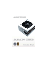
PECOS 420W ATX Power Supply Unit

SPEEDLINK PECOS 420W ATX Power Supply Unit, PECOS 420W ATX User guide

  • Hello! I am an AI chatbot trained to assist you with the SPEEDLINK PECOS 420W ATX Power Supply Unit User guide. I’ve already reviewed the document and can help you find the information you need or explain it in simple terms. Just ask your questions, and providing more details will help me assist you more effectively!
10
En
Disclaimer of liability
Jöllenbeck GmbH accepts no liability whatsoever for any product deciencies or injuries caused
to people due to careless, improper or incorrect use of the product or use of the product for
purposes not recommended by the manufacturer. Under no circumstances will Jöllenbeck GmbH
be liable for actually incurred, indirect, direct or consequential damages, loss of data, losses of
production, loss of income or lost prot, damage to property and third-party claims for
compensation. You should make a full backup of your system before formatting and partitioning
the hard drive.
Interference
Operation of the device (the devices) may be affected by strong static, electrical or high-
frequency elds (radio installations, mobile telephones, microwave discharges). If this occurs,
try increasing the distance between the devices that are causing interference.
Disposal
The markings on the product and on the associated literature show that this product must not be
disposed of together with normal household waste at the end of its useful life. Please dispose of
this device separately from other waste in order not to cause harm to the environment or human
health through uncontrolled refuse disposal. Recycle the device to facilitate the sustainable
recycling of material resources. Private users should contact the dealer from whom the product
was bought, or the authorities responsible for recycling, to nd out how to recycle the device in
an environmentally friendly way. Commercial users should ask their suppliers and consult the
sales contract terms. This product must not be disposed of together with other commercial waste.
Technical support
Our Technical Support team is there for you in the event of any questions or problems. Visit our
website: http://www.speedlink.com or send an e-mail to: [email protected]
INFORMATIONS
11
En
Power supply
Check the supply voltage before connecting. The power source used to power the power supply
unit must correspond to the values stated on the label. Never use the power supply unit to power
devices whose required voltage is lower than the one specied on the power supply unit as you
risk damaging both the power supply unit and the device.
As this device is mains powered, place it near an easily accessible AC outlet.
This device will only be completely disconnected from the mains once it has been unplugged.
Cleaning
Switch the power supply unit off and unplug it from the mains supply before cleaning it. Only
clean the outside of the device and use a soft, dry cloth to do so.
Troubleshooting/repairs
To avoid the risk of electric shock, do not open the power supply unit casing. This product does
not contain any interchangeable parts. Do not attempt to service or repair the product yourself;
leave any repairs to qualied personnel. Do not attempt to modify the product in any way as doing
so will invalidate the warranty.
Moisture/heat
Do not operate the device near water (e.g. sinks, baths, etc.) and keep it away from moisture,
areas where liquids are likely to drip or be sprayed as well as rain. Do not expose the product to
high temperatures, high humidity or direct sunlight.
IMPORTANT SAFETY NOTES
12
En
What’s included: • 1 × PSU
• 1 × Mains cable
• 1 × User manual
• 4 × Screws
• 4 × Cable ties
• 1 × PATA/SATA adapter
Model description: CP4-420-V.2.0 – 420 Watt PC Power Supply (SL-6910-SSV-01)
Form factor: ATX/ATX 2.3
Connectors: 1 × 20/24-pin main ATX (420 mm), 1 × 4-pin P4, 3 × IDE/PATA,
2 × SATA (plus 1 × PATA/SATA adapter), 1 × FDD, 1 × 6-pin PCIe
Ventilation: 120mm fan (temperature controlled)
Total power: 420W
Input voltage (AC): 200-240V, 47-53Hz, 6A
PFC: Passive PFC
Dimensions: 148 × 140 × 86mm
Weight: 1270g
Certicates: TÜV, CE, RoHS pursuant to 2002/95/EC
Manufacturer: ACOS GmbH
Kulemannstieg 34
D-22457 Hamburg
Germany
Distributor: Jöllenbeck GmbH
Kreuzberg 2
D-27404 Weertzen
Germany
Power Output
TECHNICAL INFORMATION
+3.3V
24A
+5V
21A
+12V
31A
5VSB
2.5A
-12V
0.3A
13
En
Important:
The mainboard’s power supply requirements may vary depending on the manufacturer and
product. Please refer to your mainboard’s operating instructions for detailed specications and
instructions. If you do not have the necessary level of technical knowledge to install the device,
please arrange for an expert or specialist company to install it.
Removing the old power supply unit
Set the power switch on the power supply unit to off and unplug the computer from the
mains socket. Wait around 20 minutes to allow any residual power to discharge and to allow the
power supply unit to cool down.
Following that, open the computer by unscrewing the left side panel. Now disconnect all
connections between the old power supply unit and the various components such as the
motherboard, the hard drive and graphics card, etc.Then unscrew the screws that are used to
secure the power supply unit to the back of the computer and carefully remove the power
supply unit.
Installing the new power supply unit
You can now slot the new power supply unit into the mount. When doing so, make sure that the
single ventilation grill on the inside of the computer is not blocked so that hot air from inside the
computer can be sucked in and vented to the outside.
After that, tighten the screws on the back of the computer again.
Connecting the power supply unit
You can now start connecting the components to the power supply unit. Never try and plug a
connector into a socket using force as this may result in the power supply unit and hardware
components sustaining damage which is not covered by our warranty.
INSTALLATION
14
En
20+4-pin MAIN power connector – motherboard
4-pin +12V AUX/P4 power connector – 12V AUX/P4
5-pin SATA power connector – SATA hard drives,
SATA CD-ROM/DVD drives/writers
6-pin PCI Express power connector – PCI Express graphics cards
4-pin peripheral device connector – IDE hard drives, CD-ROM drives/writers,
DVD drives/writers, AGP graphics cards
4-pin oppy connector – disc/oppy drives
First, connect the main power connector (1) on the power supply unit to the mother board.
Some motherboards require a 20-pin connector, others a 24-pin connector. For this reason the
Pecos 420W has a 20-pin connector with an additional 4-pin connector. This 4-pin 20 to 24-pin
combo connector extender must not be plugged into the 12V AUX/P4 socket. It should either be
plugged into the 24-pin extended ATX socket or, if an ATX 20-pin socket is present, must be left
unplugged.
There is a dedicated 4-pin +12V plug (2) for the 12V AUX connector which is easy to identify as it
only has two black and two yellow cables.
The 5-pin SATA power connector (3) is a very at, black connector which is used to connect the
power supply unit to a SATA hard drive or SATA CD-ROM/DVD drives or writers.
The 6-pin PCI Express power connector (4) is intended for PCI Express graphics cards. Certain
AGP graphics cards as well as IDE hard drives and CD-ROM and DVD drives and writers require
1 2 3
1
2
3
4
5
6
4 5 6
15
En
a 4-pin peripheral power connector (5).
If your computer has a disc/oppy drive, please connect this to the power supply unit using the
4-pin FDD connector (6).
Powering on the power supply unit
Check all cable connections and make sure that all devices have been connected correctly. Now
plug the power cord into the power supply unit and a mains socket. Set the switch on the power
supply unit from ‘0’ to ‘I’. If the computer boots correctly, you have connected all devices correctly
and the process of installing the power supply unit is now complete.
Pin Function Colur Pin Function Colour
1 +3.3V Orange
13
+3.3V Orange
2 +3.3V Orange +3.3Vs Brown
3 COM Black 14 -12V Blue
4 +5V Red 15 COM Black
5 COM Black 16 PS-ON Green
6 +5V Red 17 COM Black
7 COM Grey 18 COM Black
8 PWR OK Blue 19 COM Black
9 +5VSB Yellow 20 --- ---
10 +12V Yellow 21 +5V Red
11 +12V Orange 22 +5V Red
12 +3V 23 +5V Red
24 COM Black
20+4-pin MAIN power connector
CABLE DIAGRAMS
1
13
12
24
16
En
Pin Function Colour
1 +3.3V Orange
2 COM Black/Black
3 +5V Red/Red
4 COM Black/Black
5 +12V Yellow/Yellow
5-pin SATA power connector
Pin Function Colour Pin Function Colour
1 +12V Yellow 1 COM Black
2 +12V Yellow 2 COM Black
3 +12V Yellow 3 COM Black
6-pin PCI Express power connector
1
4
4-pin +12V AUX/P4 power connector
1
3
Pin Function Colour
1 COM Black
2 COM Black
3 +12V Yellow
4 +12V Yellow
17
En
4-pin peripheral device connector
Pin Function Colour
1 +12V Yellow/Yellow
2 COM Black/Black
3 COM Black/Black
4 +5V Red/Red
Pin Function Colour
1 +12V Yellow
2 COM Black
3 COM Black
4 +5V Red
4-pinoppyconnector
If the computer doesn’t boot correctly please take the following steps:
• Make sure the power switch is set to ‘I’.
Check to see if the power cord has been correctly plugged into the power supply unit and the
mains socket.
• Check to see if all components are correctly connected to the power supply unit.
Switch the power supply unit off, wait a few seconds, and then switch it back on again.
If the computer still won’t boot despite taking these steps, please refer to a specialist. You
should neither attempt to open the power supply unit nor modify the device!
TROUBLESHOOTING
white
©2010 Jöllenbeck GmbH. All rights reserved. SPEEDLINK
®
, the SPEEDLINK word mark and the SPEEDLINK swoosh
are registered trademarks of Jöllenbeck GmbH. All other trademarks are the property of their respective owners.
llenbeck GmbH shall not be made liable for any errors that may appear in this manual. Information contained
herein is subject to change without prior notice. JÖLLENBECK GmbH, Kreuzberg 2, 27404 Weertzen, GERMANY
CP4-420-V.2.0 (Sl-6910-SSV-01) | VERS. 1.1
/