- 10 -
HALOGEN BULBS
This range hood requires two halogen bulbs
(Type MR16, 12V, 20W). To change bulbs:
1. Remove the grease filter.
2. Remove bulbs by pulling them straight
downward. Do not rotate bulbs.
3. Remount the grease filter.
4. Replace bulbs by aligning the bulb’s pins
with the receptacle holes and pushing bulb
upward.
BROAN-NUTONE LLC ONE YEAR LIMITED WARRANTY
Broan-NuTone LLC warrants to the original consumer purchaser of its products that such products will be free from defects
in materials or workmanship for a period of one year from the date of original purchase. THERE ARE NO OTHER WAR-
RANTIES, EXPRESS OR IMPLIED, INCLUDING, BUT NOT LIMITED TO, IMPLIED WARRANTIES OR MERCHANT
ABILITY OR FITNESS FOR A PARTICULAR PURPOSE.
During this one-year period, Broan-NuTone LLC will, at its option, repair or replace, without charge, any product or part which
is found to be defective under normal use and service.
THIS WARRANTY DOES NOT EXTEND TO FLUORESCENT LAMP STARTERS, TUBES, HALOGEN AND
INCANDESCENDT BULBS. This warranty does not cover (a) normal maintenance and service or (b) any products or parts
which have been subject to misuse, negligence, accident, improper maintenance or repair (other than by Broan-NuTone LLC),
faulty installation or installation contrary to recommended installation instructions.
The duration of any implied warranty is limited to the one-year period as specified for the express warranty. Some states do
not allow limitation on how long an implied warranty lasts, so the above limitation may not apply to you.
BROAN-NUTONE LLC’S OBLIGATION TO REPAIR OR REPLACE, AT BROAN-NUTONE LLC’S OPTION, SHALL BE
THE PURCHASER’S SOLE AND EXCLUSIVE REMEDY UNDER THIS WARRANTY. BROAN-NUTONE LLC SHALL
NOT BE LIABLE FOR INCIDENTAL, CONSEQUENTIAL OR SPECIAL DAMAGES ARISING OUT OF OR IN CONNEC-
TION WITH PRODUCT USE OR PERFORMANCE. Some states do not allow the exclusion or limitation of incidental or
consequential damages, so the above limitation or exclusion may not apply to you.
This warranty gives you specific legal rights, and you may also have other rights, which vary from state to state. This warranty
supersedes all prior warranties.
To qualify for warranty service, you must (a) notify Broan-NuTone LLC at the address stated below or telephone: 1-800-637-
1453, (b) give the model number and part identification and (c) describe the nature of any defect in the product or part. At the
time of requesting warranty service, you must present evidence of the original purchase date.
Broan-NuTone LLC. 926 West State Street, Hartford, WI 53027 (1-800-637-1453)
NuTone, Inc., 4820 Red Bank Road, Cincinnati, OH 45227 (1-800-543-8687)
WARRANTY
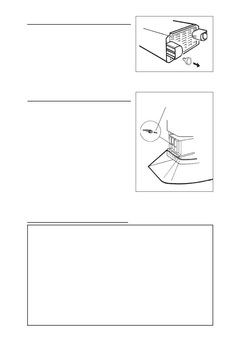
FUSE REPLACEMENT
SWITCH OFF THE ELECTRICITY SUPPLY.
Push the lower flue upwards.
Open the electrical box.
Replace with the same type of fuse (5x20mm,
4A, 125V).
FUSE


