Shindaiwa AHS2510 User manual
- Category
- Power hedge trimmers
- Type
- User manual
This manual is also suitable for

AHS2510/EVC
ARTICULATED HEDGE TRIMMER
Part Number 89311 Rev. 06/09
SHINDAIWA OWNER’S/OPERATOR'S MANUAL
English ........... 1
Español ....SP_1
Français ... FR_1
Always wear eye and ear protection when operat-
ing this machine! To minimize the risk of injury to
yourself and others, read this manual and familiarize
yourself with its contents
.
WARNING!

2
WARNING!
The engine exhaust from this
product contains chemicals known to
the State of California to cause can-
cer, birth defects or other reproduc-
tive harm.
Introduction
The Shindaiwa C4 series of hand-held
power equipment is designed and built to
deliver superior performance and reliabil-
ity without compromise to quality, comfort,
safety or durability. Shindaiwa engines
represent the leading edge of high-per-
formance engine technology, delivering
exceptionally high power with remarkably
low displacement and weight. As an owner/
operator, you’ll soon discover for yourself
why Shindaiwa is simply in a class by itself!
Throughout this manual are special “atten-
tion statements”.
Attention Statements
WARNING!
A statement preceded by the
triangular attention symbol and the
word “WARNING” contains information
that should be acted upon to prevent
serious bodily injury.
CAUTION!
A statement preceded by the word
“CAUTION” contains information
that should be acted upon to prevent
mechanical damage.
IMPORTANT!
A statement preceded by the word
“IMPORTANT” is one that possesses spe-
cial significance.
NOTE:
A statement preceded by the word “NOTE”
contains information that is handy to know
and may make your job easier.
DANGER!
A statement pre-
ceded by the triangular attention sym-
bol and the word “DANGER” contains
information that should be acted upon
to prevent serious injury or death.
IMPORTANT!
The operational procedures described in this manual are intended to help you get the most from this unit as well as to protect you and oth-
ers from harm. These procedures are guidelines for safe operation under most conditions, and are not intended to replace any safety rules
and/or laws that may be in force in your area. If you have questions regarding your Shindaiwa hand-held power equipment, or if you do not
understand something in this manual, contact Shindaiwa Inc. at the address printed on the back of this Manual.
Safety...........................................................3
Product Description...................................5
Specifications..............................................5
Assembly.....................................................6
Mixing fuel..................................................9
Filling the fuel tank....................................9
Starting the Engine .................................10
Stopping the Engine ................................11
Adjusting Engine Idle..............................11
Operation ..................................................12
Maintenance.............................................13
Long Term Storage..................................17
Troubleshooting Guide ...........................18
Emission System Warranty.....................21
Shindaiwa Inc. reserves the right to make
changes to products without prior notice,
and without obligation to make alterations
to units previously manufactured.
IMPORTANT!
The information contained in these instruc-
tions describes units available at the time
of publication.
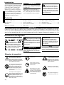
Safety and operation labels
Contents
PAGE PAGE
PAGE
Read and follow this manual,
make sure anyone using the trim-
mer does likewise. Failure to do
so could result in serious personal
injury or machine failure. Keep
this manual for future reference.
Safety tip shoes or boots with
non-slip sole should be worn.
Keep bystanders at least 50
feet (15 meters) away from the
operating trimmer to reduce
the risk of being cut by the cut-
ting blades or struck by falling
objects or thrown debris.
This product conducts electricity.
Keep the product and/or opera-
tor a minimum distance of 33
feet (10 meters) away from elec-
trical sources and power lines.
Be aware of the danger of fall-
ing debris.
33 ft
10 M
Always wear a hard hat to reduce
the risk of head injuries during
operation of this machine. In addi-
tion, always wear eye and hearing
protection. Shindaiwa recom-
mends wearing a face shield as
additional face and eye protection.
Wear non-slip heavy-duty
gloves.
The blades / cutting attach-
ments are SHARP! Handle
with care.
An articulated hedge trimmer has
the potential to cause serious
personal injury to the operator or
bystanders if misused, abused or
mishandled. You must observe
all special safety iinstructions to
reduce the risk of personal injury.

3
DANGER!
THE ARTICULATED
HEDGE TRIMMER IS NOT INSULATED
AGAINST ELECTRICAL SHOCK!
Approaching or contacting electrical
lines with the trimmer could cause
death or serious injury. Keep the trim-
mer at least 10 meters away from
electrical lines or branches that con-
tact electrical lines.
Safety
Operating Precautions
Never transport the articulated hedge Ŷ
trimmer or leave it unattended with the
engine running. An engine that’s run-
ning could be accidently accelerated
causing the blades to oscillate.
Make sure that the blade cover is in
Ŷ
place when transporting or storing the
articulated hedge trimmer.
Always make sure that the cutter
Ŷ
attachment and all handles and guards
DUHSURSHUO\LQVWDOOHGDQG¿UPO\WLJKW-
ened before operation.
Inspect for broken, missing or improp-
Ŷ
erly installed parts or attachments.
Never use a cracked or warped cutter
Ŷ
or cutter bar: replace it with a service-
DEOHRQHDQGPDNHVXUHLW¿WVSURSHUO\
Make sure there are no missing or loose
Ŷ
fasteners, and that the stop switch and
throttle controls are working properly.
Ŷ Make sure there is always good ven-
tilation when operating the articulated
hedge trimmer. Fumes from engine
exhaust can cause serious injury or
death. Never run the engine indoors!
1HYHUVPRNHRUOLJKW¿UHVQHDUWKH
Ŷ
hedge trimmer. Keep the unit away
from excessive heat. Engine fuel is very
ÀDPPDEOHDQG¿UHFRXOGOHDGWRVHULRXV
personal injury or property damage.
When carrying the articulated hedge
Ŷ
trimmer by hand, the cutter attachment
should be pointing backward with the
cutter blade in the retracted or trans-
porting position. (Refer to the section,
”Transporting the Articulated Hedge
Trimmer”.)
Do not operate this machine with the
Ŷ
PXIÀHUUHPRYHG
Make sure the cutters are correctly
Ŷ
adjusted before operating the articu-
lated hedge trimmer (see the section
”Cutter Adjustment” for cutter adjust-
ment procedures). Never attempt cut-
ter adjustment with the engine running!
Before starting the engine, make sure
Ŷ
the cutter is not contacting anything.
$OZD\VFRQ¿UPVDIHRSHUDWLRQZKHQ
Ŷ
using the machine, especially when
operating on steps or a ladder.
Immediately stop the engine with the
Ŷ
stop switch if the machine suddenly
begins to vibrate or shake.
Always stop the engine immediately
Ŷ
and check for damage if you strike
a foreign object or if the machine
becomes tangled. Do not operate with
broken or damaged equipment.
When cutting a branch that is under
Ŷ
tension, be alert for spring-back so that
you will not be struck by the moving
branch.
If a cutter should bind fast in a cut,
Ŷ
shut off the engine immediately. Push
the branch or tree to ease the bind and
free the cutter.
Always stop the engine and allow it to
Ŷ
FRROEHIRUHUHIXHOLQJ$YRLGRYHU¿OOLQJ
and wipe off any fuel that may have
spilled.
7RUHGXFH¿UHKD]DUGNHHSWKHHQJLQH
Ŷ
DQGPXIÀHUIUHHRIGHEULVOHDYHVRU
excessive grease.
CAUTION!
Always maintain the articulated
Ŷ
hedge trimmer according to this own-
er’s manual and follow the recom-
mended scheduled maintenance.
Never modify or disable any of the
Ŷ
hedge trimmer’s safety devices.
Doing so may cause damage and
lead to personal injury
Always use genuine Shindaiwa parts
Ŷ
and accessories when repairing or
maintaining this machine.
'RQRWPDNHXQDXWKRUL]HGPRGL¿FD-
Ŷ
tions to the articulated hedge trimmer
or its components.
Keep the cutters sharp and properly
Ŷ
adjusted.
Never allow the engine to run at high
Ŷ
without a load. Doing so could dam-
age the engine.
When transporting the hedge trim-
Ŷ
mer in a vehicle, tie it down securely
to prevent fuel spillage or damage to
the machine.
Always stop the engine and allow it
Ŷ
to cool before refueling. Avoid over-
¿OOLQJDQGZLSHRIIDQ\IXHOWKDWPD\
have spilled.
1HYHUSODFHÀDPPDEOHPDWHULDOFORVH
Ŷ
WRWKHHQJLQHPXIÀHUDQGQHYHUUXQ
the engine without the spark arrestor
screen in place.
Always clear your work area of trash
Ŷ
or hidden debris to help ensure
good footing.
Keep the articulated hedge trimmer
Ŷ
as clean as possible. Keep it free of
loose vegetation, mud, etc.
An articulated hedge trimmer has the
potential to cause serious personal injury
to the operator or bystanders if misused,
abused or mishandled. To reduce the risk
of injury, you must maintain control at all
times, and observe all safety precautions
during operation. Never permit a person
without training or instruction to operate
this trimmer!
WARNING!
WARNING!
Do not make unauthorized
PRGL¿FDWLRQVRUDOWHUDWLRQVWR\RXUDUWLF-
ulated hedge trimmer or its components.
Never operate this tool or any other
power equipment if you are tired, ill, or
XQGHUWKHLQÀXHQFHRIDOFRKROGUXJV
or any substance that could affect
your ability or judgement.
WARNING!

Handle
Ignition
(STOP)
switch
Throttle
interlock
Cutter blade cover
4
Safety (continued)
Operator Safety
Wear sturdy footwear with nonslip
soles to provide good footing.
Steel-toed safety boots are
recommended. Never operate
machine bare-footed.
Keep bystanders at least
15 meters away from the
operating trimmer to reduce
the risk of being struck by
falling objects or thrown
debris.
Always operate with both hands
¿UPO\JULSSLQJWKHPDFKLQH
Always wear a hard hat
to reduce the risk of head
injuries during operation of
this machine.
Always wear eye and hearing protection.
Shindaiwa recommends wearing a
face shield as additional face and eye
protection.
Keep a proper footing
and do not overreach—
maintain your balance
at all times during
operation.
This machine is designed
for trimming hedges. Do
not use this machine for
other purposes.
NEVER allow children to
use the unit. Avoid operating
near bystanders or when
children are nearby.
$/:$<6ZHDUFORVH¿WWLQJ
clothing. Gloves offer added
proctection and are strongly
recommended. Do not wear
clothing or jewelry that could
get caught in machinery.
ALWAYS protect
yourself from hazards
such as thorny brush
DQGÀ\LQJGHEULVE\
wearing gloves and
FORVH¿WWLQJFORWKLQJ
that covers arms and
legs. Never wear
shorts. Don't wear loose
clothing or items such
as jewelry that could
get caught in machinery
or underbrush. Secure
long hair so it is above
shoulder level.
ALWAYS clear your work area
of trash or hidden debris that
could be thrown back at you or
toward a bystander.
ALWAYS be aware of
your surroundings and
alert to any danger that
you may not hear due to
machine noise.
Safety Equipment and Labels
IMPORTANT!
Caution, Danger, Warning, and Operation
Information Labels: Make sure all informa-
tion labels are undamaged and readable.
Immediately replace damaged or missing
information labels. New labels are available
from your local authorized Shindaiwa dealer.

5
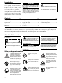
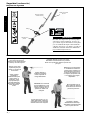
Product Description
Using the illustration as a
guide, familiarize yourself
with the Shindaiwa AHS2510
articulated hedge trimmer
and its various components.
Understanding your machine
helps ensure top performance,
longer service life, and safer
operation.
Handle
Outer
Tube
Hedge Trimmer Cutter
Assembly
Cutter
Assembly
Adjustment
Lever
Cutter
Blade
Cover
Fuel
Tank
Guard
Gearcase
Hedge Trimmer
Cutter Assembly
Cutter Bar and
Cutter Blades
Latch
Release
Latch Lock
Air Filter
Assembly
Powerhead Assembly
Spark Plug
Fuel
Tank
Ignition
Throttle
interlock
Fuel Tank
Guard
Throttle Trigger
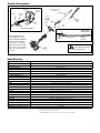
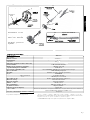
6SHFLÀFDWLRQV
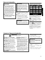
* The EPA emission compliance referred to on the emission compliance label located on the engine, indicates the number of operat-
ing hours for which the engine has been shown to meet Federal emission requirements. Category C = 50 hours (Moderate), B = 125
hours (Intermediate) and A = 300 hours (Extended).
** The NGK CMR5H also meets the requirements for electro magnetic compliance (EMC).
Specifications are subject to change without notice.
Model AHS2510
Engine Type 4-cycle, vertical cylinder, air cooled
Engine Bore x Stroke 34 x 27 mm/1.34 x 1.06 in.
Engine Displacement 24.5cc/1.5 cu. in.
Unit Weight, Less Fuel 6.2 kg/13.6 lbs.
Unit Dimensions (LxWxH) 1670 x 197 x 250 mm / 65,8 x 7,8 x 9,9 in.
Max. Power 7,500 min
-1
(rpm)
Recommended idle speed 3,000 (±300) min
-1
Fuel Tank Capacity 590 ml/20 oz..
Fuel/oil ratio 50:1 with *ISO-L-EGD or JASO FC class 2-cycle Mixing Oil
Carburetor Walbro WYL, Diaphragm type
Ignition Fully electronic, program controlled
Spark Plug NGK CMR5H
Electrode Gap 0.6 - 0.7 mm/ .024 -.028 in.
Torque 100-150 kg cm / 9.8 - 14.7 N∙m
Air Cleaner Foam pre-filter; main filter: dry element
Starting Method Recoil type
Stopping Method Slide switch, grounding type
Blade Length 590 mm / 20.3 in
Clutch Type Automatic, centrifugal clutch with bevel gear
Gear Type Spur gears
Gear Lubrication Lithium-based grease
Standard Equipment
Tool kit w/ spark plug wrench, 4mm hex wrench, 8 x 10 mm spanner, front handle w/guard, tool set, blade scabbard.
EPA Emission Compliance Period* Category A
WARNING!
Do not alter this machine
or any of its components!

6
Assembly
This unit comes fully assembled. You
only need attach the accessory tool of
your choice to the powerhead. Your unit
includes:
Engine/outer tube assembly
Ŷ
Gearcase/cutter assemblyŶ
Prior To Assembly
This manual and tool kit for routine Ŷ
maintenance.
Cutter blade cover
Ŷ
Carefully inspect all components for
damage.
IMPORTANT!
The terms “left”, “left-hand”, and “LH”;
“right”, “right-hand”, and “RH”; “front” and
“rear” refer to directions as viewed by the
operator during normal operation.
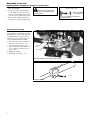
Index Screw
Gearcase/Cutter
Assembly
Mainshaft
Tube
Clamp
Outer Tube
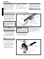
Place the powerhead/outer tube assem-1.
bly on a clean, flat surface, spark plug
facing up.
Use the 4mm hex wrench to loosen the 2.
tube clamp and index screw. Verify that
the D-shaped shim washer is positioned
as shown.
Connect the Powerhead/Outer Tube to the Gearcase
Clamp Screw
D-Washer
Index Hole
CAUTION!
Do not force the shaft tube into the
gearcase! Excessive force can dam-
age the shaft tube and mainshaft.
CAUTION!
Do not remove the D-shaped shim
washer! The shim washer prevents
damage from overtightening the
tube clamp screw.
Slide the outer tube into the tube clamp 3.
until the tube bottoms. If installation is
difficult, rotate the outer tube or main
shaft slightly until you feel the main-
shaft splines engage with the gearcase.
Position the outer tube so that the index 4.
hole on the outer tube is aligned with the
index screw on the gearcase tube clamp.
Using finger pressure only, thread the 5.
index screw into the index hole located
on the outer tube until it bottoms out.
Tighten the index screw and the clamp 6.
screw firmly.
NOTE:
It may be necessary to twist the outer tube
slightly for the index screw to be inserted fully.
Outer Tube
Socket-head
Capscrews
Handle
Mounting Bracket
Throttle Assembly
Position the handle on the outer tube as shown
Connect the outer tube to the gearcase
Handle
This unit comes with the handle installed.
It can be re-adjusted for operator comfort
in the following manner.
Loosen the four hex screws.1.
Rotate/slide handle assembly to best 2.
position for operator comfort, usually
25 cm (10 in.) ahead of the throttle
assembly.
Tighten hex screws in a crisscross 3.
manner.

7
The cutter blades are very sharp. Ŷ
Do not grasp the blades with your
hands. Always use gloves when
working near the cutter assembly.
Do not allow the blades to contact
Ŷ
your body.
Do not touch the cutter blades
Ŷ
when the engine is running. The
blades can oscillate even if the
engine is idling.
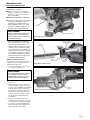
Adjusting the Hedge Trimmer Cutter Assembly
Assembly (continued)
WARNING!
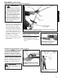
With your right hand, grasp the outer 1.
tube near the handle. With your left
hand, grip the adjustment lever on the
cutter assembly.
With the index finger of your left hand, 2.
press the latch lock. With your left
thumb, press the latch release.
While holding the latch release down, 3.
pivot the cutter assembly using the
adjustment lever until it is at the
desired cutting angle.
Release the latch lock and the latch 4.
release. Make sure the latch lock and
the latch release return securely to the
straight ahead position.
Latch release
Latch lock
Adjustment lever
IMPORTANT!
The latch lock provides an interlock to
help prevent inadvertent depression of the
latch release.
:LWKWKHLQGH[¿QJHURI\RXUOHIWKDQGSUHVV
WKHODWFKORFN:LWK\RXUOHIWWKXPESUHVV
the latch release.
:LWK\RXUULJKWKDQGJUDVSWKHRXWHUWXEHQHDUWKHKDQGOH:LWK\RXUOHIWKDQGJULSWKH
adjustment lever on the cutter assembly
Handle
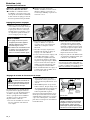
Travel Limiter
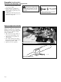
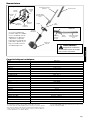
The cutter assembly can be adjusted to
10 different positions ranging from 90° to
225° from the outer tube as shown. Always
make sure the lock latch is securely locked
after each adjustment.
NOTE:
This articulated hedge trimmer is
equipped with a travel limiter that pre-
vents the cutter assembly from rotating
outside of the 90°- 225° range.
7KHWUDYHOOLPLWHUSUHYHQWVWKHFXWWHU
DVVHPEO\IURPURWDWLQJRXWVLGHRIWKH
UDQJH
7KHFXWWHUDVVHPEO\FDQEHDGMXVWHGWR
GLIIHUHQWSRVLWLRQV
Remove the cover from the cutter 5.
blade. The engine now may be started
(refer to the section ”Starting the
Engine”.)
Grasp the outer tube
near the handle
Outer tube
Travel limiter and adjustment range
Latch lock
Latch release
WARNING!
Always make sure the lock
latch is securely locked after each
adjustment
Various
positions
possible
225°
135°
90°

Cable
Adjuster
Lock Nut
5RWDWHFDEOHDGMXVWHULQRURXWWRREWDLQSURSHUIUHHSOD\
4 - 6 mm
7KURWWOHOHYHUIUHHSOD\
8
The throttle lever free play should be
approximately 4 - 6 mm. Make sure that
the throttle lever operates smoothly with-
out binding. If it becomes necessary to
adjust the lever free play, follow the pro-
cedures and illustrations that follow.
Loosen the air cleaner cover knob(s) 1.
and remove the air cleaner cover.
Loosen the lock nut on the cable 2.
adjuster. Turn the cable adjuster in or
out as required to obtain proper free
play 4 - 6 mm.
Tighten the locknut.3.
Reinstall the air cleaner cover.4.
Throttle lever free play
Adjusting cutter assembly for storage or transportation
Assembly (continued)
With the engine off, install the scab-1.
bard onto the blade.
Release the latch lock and the latch 2.
release. Make sure the cutter blades,
latch lock, and the latch release return
securely to the straight ahead position.
Make sure the scabbard is in place on 3.
the blade before storing or transporting.
WARNING!
Never run the engine when
adjusting the cutter assembly to the
storage position.
0DNHVXUHWKHVFDEEDUGLVLQSODFHEHIRUH
VWRULQJRUWUDQVSRUWLQJ
Transport / storage position

9
NEVER
Ŷ VPRNHRUOLJKW¿UHVQHDUWKH
engine.
ALWAYS
Ŷ stop the engine and allow
it to cool before refueling.
ALWAYS
Ŷ Wipe all spilled fuel and
move at least 3 meters (10 feet) from
the fueling point and source before
starting.
NEVER
Ŷ SODFHÀDPPDEOHPDWHULDO
FORVHWRWKHHQJLQHPXIÀHU
NEVER
Ŷ
operate the engine without the
PXIÀHUDQGVSDUNDUUHVWHUVFUHHQLQ
place and in good working condition.
FUEL IS HIGHLY FLAMMABLE.
Ŷ
ALWAYS
Ŷ
store gasoline in a con-
WDLQHUDSSURYHGIRUÀDPPDEOHOLTXLGV
ALWAYS
Ŷ
inspect the unit for fuel
leaks before each use. During each
UH¿OOFKHFNWKDWQRIXHOOHDNVIURP
around the fuel cap and/or fuel tank. If
fuel leaks are evident, stop using the
unit immediately. Fuel leaks must be
repaired before using the unit.
ALWAYSŶ move the unit at least 3
meters (10 feet) away from a fuel
VWRUDJHDUHDRURWKHUUHDGLO\ÀDP-
mable materials before starting the
engine.
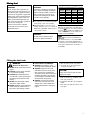
Mixing fuel
Filling the fuel tank
CAUTION!
This engine is designed to operate on
a 50:1 mixture consisting of unleaded
gasoline and ISO-L-EGD or JASO FD
class 2-cycle mixing oil only. Use of
non-approved mixing oils can lead to
excessive carbon deposits.
Use only fresh, clean unleaded gasoline Ŷ
with a pump octane of 87 or higher.
Mix all fuel with a 2-cycle air-cooled
Ŷ
mixing oil that meets or exceeds ISO-L-
EGD and/or JASO FD classified oils at
50:1 gasoline/oil ratio.
Examples of 50:1 mixing quantities
WARNING!
Minimize the Risk of Fire
IMPORTANT!
Mix only enough fuel for your immediate
needs! If fuel must be stored longer than 30
days and
oil with fuel stabilizer is not
used, it should first be treated with a fuel
stabilizer such as STA-BIL™.
Oil is a registered JASO FD classi-
fied oil and also meets or exceeds ISO-L-EGD
performance requirements. Shindaiwa One is
recommended for use in all Shindaiwa low emis-
sions engines. Shindaiwa One also includes a
fuel stabilizer.
Mixing fuel
CAUTION!
Never use any type of gasoline con-
taining more than 10% alcohol by vol-
ume! Some types of gasoline contain
alcohol as an oxygenate. Oxygenated
gasoline may cause increased operat-
ing temperatures. Under certain con-
ditions, alcohol-based gasoline may
also reduce the lubricating qualities of
some 2-cycle mixing oils.
Generic oils and some outboard
oils should never be used in your
Shindaiwa engine.
Place the unit on a flat, level surface.1.
Clear any dirt or other debris from 2.
around the fuel filler cap.
Remove the fuel cap, and fill the tank 3.
with clean, fresh fuel.
Reinstall the fuel filler cap and tighten 4.
firmly.
Wipe away any spilled fuel before start-5.
ing engine.
CAUTION!
Slowly remove the fuel cap only after
stopping the engine
CAUTION!
Mix and pour fuel outdoors where
WKHUHDUHQRVSDUNVDQGÀDPHV
U.S. METRIC
Gasoline
2-cycle
mixing oil
Gasoline
2-cycle
mixing oil
US Gallons Fl.oz. Liter cc.
1 2.6 4 80
2 5.2 8 160
5 13 20 400
10 25.6 30 600
20 51.2 50 1000
50 128 100 2000

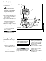
Slide ignition to ON
ON
Throttle Lock
Button
Make sure the
attachment is clear
of obstructions!
...and pull recoil
starter handle
upward
Hold
the unit
¿UPO\
Open
$IWHUHQJLQHVWDUWVPRYHFKRNHWR23(1
SRVLWLRQ
Primer Bulb
Return Tube
3UHVVSULPHU
bulb...
Close
choke
6HWWKHFKRNHOHYHUWRWKH&/26('SRVLWLRQ
10
Starting the Engine
IMPORTANT!
Engine ignition is controlled by a two position switch mounted on the throttle housing labeled, “I” for ON or START and “O” for OFF or STOP.
Slide the ignition switch to the “ON” 1.
position.
Set the throttle lever to the “fast idle”:2.
Squeeze the throttle lever toward a.
the handgrip on the shaft tube.
Depress and hold the throttle lock b.
button.
While depressing the throttle lock c.
button, release the throttle lever.
Press the primer bulb until fuel can 3.
be seen flowing in the transparent
return tube.
WARNING!
Never start the engine from
the operating position.
Set the choke lever to the CLOSED 4.
position if engine is cold.
While holding the outer tube firmly 5.
with left hand. Use your other hand
to slowly pull the recoil starter handle
until resistance is felt, then pull quickly
to start the engine.
IMPORTANT!
The primer system only pushes fuel
through the carburetor. Repeatedly press-
ing the primer bulb will not flood the
engine with fuel.
CAUTION!
Do not pull the recoil starter to the end
of the rope travel. Pulling the recoil
starter to the end of the rope travel
can damage the starter.
WARNING!
The cutting attachment may
move when the engine is started!
IMPORTANT!
If the engine fails to start after several
attempts with the choke in the closed
position, the engine may be flooded with
fuel. If flooding is suspected, refer to the
”Starting a Flooded Engine” section of
this manual.
When the engine starts, slowly move 6.
the choke lever to the “OPEN” posi-
tion. (If the engine stops after the initial
start, close the choke and restart.)
Operating the throttle will automatically 7.
disengage the fast idle setting.
After the engine starts, allow the
Ŷ
engine to warm up at idle 2 or 3 min-
utes before operating the unit.
After the engine is warm, pick up the
Ŷ
unit and clip on the shoulder strap, if
so equipped.
When the Engine Starts...
Advancing the throttle makes the cutting Ŷ
attachment move faster; releasing the
throttle permits the attachment to stop
moving. If the cutting attachment con-
tinues to move when the engine returns
to idle, carburetor idle speed should be
adjusted (see “Adjusting Engine Idle”.).

Slide ignition to OFF
OFF
NEVER operate the unit with the cut-
ting attachment shield or other protec-
tive devices removed!
Use only authorized Shindaiwa parts and
accessories with your Shindaiwa trimmer.
Do not make modifications to this unit with-
out written approval from Shindaiwa, Inc.
ALWAYS make sure the cutting attach-
ment is properly installed and firmly
tightened before operation.
NEVER use a cracked or warped
cutting attachment: replace it with a
serviceable one.
Checking Unit Condition
ALWAYS make sure the cutting attach-
ment fits properly into the appropriate
attachment holder. If a properly installed
attachment vibrates, replace the attach-
ment with new one and re-check.
ALWAYS stop the engine immediately
and check for damage if you strike a
foreign object or if the unit becomes
tangled. Do not operate with broken or
damaged equipment.
NEVER allow the engine to run at high
RPM without a load. Doing so could dam-
age the engine.
NEVER operate a unit with worn or dam-
aged fasteners or attachment holders.
WARNING!
A cutting attachment shield or
other protective device is no guarantee
of protection against ricochet. YOU
MUST ALWAYS GUARD AGAINST
FLYING DEBRIS!
11
Idle the engine briefly before stopping
(about 2 minutes), then slide the ignition
switch to the “O” (Engine OFF) position.
Stopping the Engine
Adjusting Engine Idle
Idle Adjusting
Screw
The engine must return to idle speed
whenever the throttle lever is released.
Idle speed is adjustable, and must be set
low enough to permit the engine clutch to
disengage the cutting attachment.
WARNING!
The cutting attachment must
NEVER rotate at engine idle! If the
idle speed cannot be adjusted by
the procedure described here, return
the unit to your Shindaiwa dealer for
inspection.
Idle Speed Adjustment
Place the unit on the ground, then start 1.
the engine, and then allow it to idle 2-3
minutes until warm.
If the attachment rotates when the 2.
engine is at idle, reduce the idle speed
by turning the idle adjustment screw
counter-clockwise.
If a tachometer is available, adjust idle. 3.
Check Specifications page for correct
idle speed
Starting the Engine (continued)
NOTE
Carburetor fuel mixture adjustments are
preset at factory and cannot be serviced
LQWKH¿HOG
Disconnect the spark plug lead and use 1.
the spark plug wrench to remove the
spark plug (turn counter clockwise to
remove).
Slide the ignition switch to the “O” 2.
(STOP) position.
If the spark plug is fouled or
Ŷ
soaked with fuel, clean the plug as
necessary.
Open the choke and fully depress the 3.
throttle lever with your left hand, then
pull the starter handle rapidly with your
right hand to clear excess fuel from the
combustion chamber.
Replace the spark plug and tighten it 4.
firmly with the spark plug wrench. If a
torque wrench is available, torque the
spark plug to the values recommended
in the “Specifications” section.
Repeat the starting procedure for a 5.
warm engine.
If the engine still fails to start, refer to 6.
the troubleshooting section near the
end of this manual.
Starting A Flooded Engine

12
Operation
Safe Operation
This machine is designed especially for
trimming hedges.
Never use this machine for any other pur-
poses. Never try to cut stones, metals, plas-
tics or any other hard objects. Using this
Articulated Hedgetrimmer for other pur-
poses than trimming hedges may damage
the machine or cause serious injury.
Before trimming:
Wear suitable protective clothing and Ŷ
equipment. See the section “Safety:
The Properly Equipped Operator” for
information.
Choose the best working position
Ŷ
for safety against the falling objects
(branches, etc.).
Start the engine.
Ŷ
Put on the strap, if so equipped.Ŷ
Rest when you feel fatigued.Ŷ
Never stand directly underneath the Ŷ
branch you are cutting. Be aware of
falling branches. Note that a branch
may spring back at you after it hits the
ground.
NOTE:
Rest when you feel fatigued.
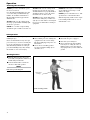
Working Position
Hold the shaft grip above the power-Ŷ
head with your right hand, and the loop
handle with your left hand.
Your left arm should be extended to
Ŷ
the most comfortable position.
2SHUDWRULQZRUNLQJSRVLWLRQ
Right hand on
shaft grip
Hold the loop
handle with your
left hand
Checking Unit Condition
ALWAYS make sure the cutting attach-
ment fits properly into the appropriate
attachment holder. If a properly installed
attachment vibrates, replace the attach-
ment with new one and re-check.
ALWAYS stop the engine immediately
and check for damage if you strike a for-
eign object or if the unit becomes tangled.
Do not operate with broken or damaged
equipment.
NEVER allow the engine to run at high
speeds without a load. Doing so could
damage the engine.
NEVER operate a unit with worn or dam-
aged fasteners or attachment holders.
When transporting, make sure the engine
is not running and the blade is covered
with the blade cover.
NEVER operate the unit with the protec-
tive devices removed!
Use only authorized Shindaiwa parts and
accessories with your Shindaiwa hedge
trimmer. Do not make modifications to
this unit without written approval from
Shindaiwa, Inc.
ALWAYS make sure the cutting attach-
ment is properly installed and firmly tight-
ened before operation.
NEVER use a cracked or warped cutting
attachment: replace it with a serviceable one.

13
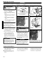
Prior to each work day, perform the
following:
Remove all dirt and debris from the
Ŷ
engine, check the cooling fins and
air cleaner for clogging, and clean as
necessary.
Carefully remove any accumulations
Ŷ
of dirt or debris from the muffler and
fuel tank. Check cooling air intake
area at base of crankcase. Remove
all debris. Dirt build-up in these areas
can lead to engine overheating, fire,
or premature wear.
Daily maintenance
Lubricate the blades before use and Ŷ
after refueling. Check the cutters for
damage or incorrect adjustment.
Clean any debris or dirt from the cut-
Ŷ
ting attachment.
5HPRYHDOOGLUWDQGGHEULVIURPWKHHQJLQHDQGFKHFNWKHFRROLQJ¿QV
Cooling
¿QV
Air
intake
Cooling
¿QV
WARNING!
Always wear gloves when
working around the cutter assembly.
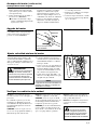
Maintenance
WARNING!
Before performing any mainte-
nance, repair, or cleaning work on the
unit, make sure the engine and cutting
attachment are completely stopped.
Disconnect the spark plug wire before
performing service or maintenance.
WARNING!
Non-standard accessories, cut-
ting attachment, or replacement parts
may not operate properly with your unit
and may cause damage and lead to
personal injury.
IMPORTANT!
MAINTENANCE, REPLACEMENT
OR REPAIR OF EMISSION CONTROL
DEVICES AND SYSTEMS MAY BE PER-
FORMED BY ANY REPAIR ESTABLISH-
MENT OR INDIVIDUAL; HOWEVER, WAR-
RANTY REPAIRS MUST BE PERFORMED
BY A DEALER OR SERVICE CENTER
AUTHORIZED BY SHINDAIWA INC. THE
USE OF PARTS THAT ARE NOT EQUIVA-
LENT IN PERFORMANCE AND DURA-
BILITY TO AUTHORIZED PARTS MAY
IMPAIR THE EFFECTIVENESS OF THE
EMISSION CONTROL SYSTEM AND MAY
HAVE A BEARING ON THE OUTCOME
OF A WARRANTY CLAIM.
0XIÁHU
This unit must never be operated with a
faulty or missing spark arrester or muf-
fler. Make sure the muffler is well secured
and in good condition. A worn or damaged
muffler is a fire hazard and may also cause
hearing loss.
Spark Plug
Keep the spark plug and wire connections
tight and clean.
Fasteners
Make sure nuts, bolts, and screws (except
carburetor adjusting screws) are tight.
General maintenancel
NOTE:
Using non-standard replacement parts
could invalidate your Shindaiwa warranty.
Air Filter
The C4 engine that powers your Shindaiwa
model is a hybrid 4-stroke engine. As a
hybrid, the engine is lubricated by oil mixed
with the gasoline and air from the carburetor
that moves through and around the internal
parts of the engine in a similar way that a
2-stroke engine is lubricated. Without the
heavy duty 2-stage air filter equipped on all
C4 engines, dust and dirt could also move
through the engine, decreasing engine life,
increasing valve wear and the need for more
frequent valve adjustments. To keep your
C4 engine strong and reliable, Shindaiwa
recommends that you check and service the
air filter as instructed in the 10-Hour Mainte-
nance section that follows.
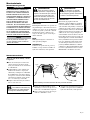
Check for loose or missing screws or Ŷ
components. Make sure the cutter
attachment is securely fastened.
Check the entire unit for leaking fuel
Ŷ
or grease.
Make sure nuts, bolts, and screws
Ŷ
(except carburetor idle speed adjusting
screws) are tight.

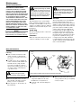
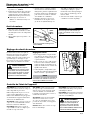
Lubricate cutter assembly and gearcase
Gearcase
JUHDVH¿WWLQJ
A
5HPRYHDQGLQVSHFWVSDUNSOXJ
0,6 - 0.7 mm
Clean the spark
plug and check
the gap at the
electrode.
&RPSRQHQWVRIDLU¿OWHU
Filter element
3UH¿OWHU
Loosen
fasteners
5HPRYHWKHFRYHURIWKHDLU¿OWHU
14
Lubricate the cutter assembly Ŷ
gearcase by pumping one or two
strokes of lithium-base grease into the
grease fitting (A) using a lever-type
grease gun.
CAUTION!
Before removing the spark plug, clean
the area around the plug to prevent
dirt and debris from getting into the
engine’s internal parts.
10/15-Hour maintenance
Maintenance (continued)
CAUTION!
Over lubricating can cause the gear-
case to operate sluggishly and can
cause grease to leak out.
Gearcase lubrication
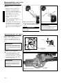
10-Hour maintenance
(more frequently in dusty conditions)
Remove the air filter cover by loosen-1.
ing the cover screw(s) and lifting.
Remove and inspect the pre-filter. If 2.
the pre-filter is torn or otherwise dam-
aged, replace it with a new one.
Clean the pre-filter with soap and water. 3.
Let dry before reinstalling.
Inspect the air filter element. If the ele-4.
ment is damaged or distorted, replace it
with a new one.
Tap filter gently on a hard surface to dis-5.
lodge debris from element or use com-
pressed air from the inside to blow debris
out and away from the air filter element.
Install the air filter element, pre-fil-6.
ter and cover in the reverse order of
removal.
IMPORTANT!
Direct the air stream at the inside face of
the filter only!
CAUTION!
Never operate the unit if the air cleaner
assembly is damaged or missing!
Remove and clean or replace the spark
plug.
Clean the spark plug. Adjust electrode
Ŷ
gap according to the values listed in the
”Specifications” section. If the spark plug
must be replaced, use only the type rec-
ommended in ”Specifications” or equiva-
lent resistor type spark plug of the correct
heat range.

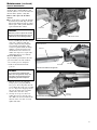
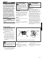
Lubricate cutter assembly and gearcase
Gearcase
JUHDVH¿WWLQJ
B
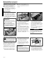
)XHO¿OWHUPDLQWHQDQFH
)XHO¿OWHUHOHPHQW
Hooked wire
Outer tube
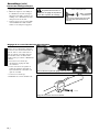
Gearcase
Gearcase Clamp bolt
Index bolt
5HPRYHWKHRXWHUWXEHIURPWKHJHDUFDVH
Gearcase lubrication
15
Maintenance (continued)
CAUTION!
Do not remove the D-shaped shim
washer from the gearcase clamp! The
shim washer prevents damage from
overtightening the tube clamp bolt.
Slide the gearcase out of the tube. 3.
Using a grease gun, pump lithium-
base grease (about 10 grams) into the
grease fitting (B) on the gearcase until
you see old grease being purged from
the gearcase. Purged grease will be
visible in the outer tube cavity.
Clean up excess grease, then reas-4.
semble the gearcase onto the outer
tube. Make sure the index bolt fits into
the hole on the outer tube. Securely
tighten both bolts.
50-hour maintenance
Every 50 hours of operation; more fre-
quently in dusty conditions:Remove and
clean the cylinder cover and clean dirt and
debris from the cylinder cooling fins.
Remove and replace the fuel filter
element.
Use a hooked wire to extract the fuel filter
Ŷ
from inside the fuel tank. Inspect the fuel
filter element. If it shows signs of contam-
ination, replace with a genuine Shindaiwa
replacement fuel filter element.
CAUTION!
Make sure you do not pierce the fuel line
with the end of the hooked wire. The line
is delicate and can be damaged easily.
Before reinstalling the new filter element,
inspect the condition of all the fuel
system components (fuel pick-up line,
fuel return line, tank vent line, tank
vent, fuel cap and fuel tank). If damage,
splitting or deterioration is noted, the
unit should be removed from service
until it can be inspected or repaired by a
Shindaiwa-trained service technician.
Gearcase lubrication
To perform this operation, first remove the
gearcase from the outer tube as follows:
Loosen the gearcase clamp bolt.1.
Remove the index bolt from the 2.
gearcase.

16
Maintenance (continued)
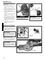
Cutting performance of your machine
depends a great deal on proper cutter blade
adjustment. Properly adjusted blades will
oscillate freely yet help prevent binding of
cut material between blades. Adjust blades
as follows:
Loosen all blade locknuts at least one 1.
full turn.
Tighten each blade shoulder bolt 2.
firmly, and then loosen the shoulder
bolts 1/4 to 1/2 turn.
Locknut
Guide Bar
Cutter
Blades
Shoulder Bolt
Washer (should
turn freely)
Adjusting cutter blades
Cutter blade adjustment
Working from the gearcase end, lock 3.
each bolt in place by firmly tightening
its locknut while preventing the shoul-
der bolt from turning.
When shoulder bolt adjustment is cor-
rect, there should be a gap of 0.25–0.50
mm between the cutter blades and the flat
washers, and the flat washer beneath each
bolt head should turn freely.
WARNING!
The cutter blades are very
sharp! Always wear gloves when work-
ing around the cutter assembly.
CAUTION!
Operating the trimmer with worn or
improperly adjusted cutters will reduce
cutter performance and may also dam-
age your machine. Never operate the
machine with damaged or worn cutters.
IMPORTANT!
If a new gasket is not available and/or the
old gasket is not damaged, the old gasket
may be reused. Never use cracked or dam-
aged gaskets!
Turn engine over several times, and 6.
returnthe to TDC-compression.
Recheck with proper feeler gauge to
make sure clearance adjustment did
not change as a result of tightening the
locknut. Readjust as necessary.
Replace rocker arm cover gasket to 7.
assure proper sealing and install cover.
139/150-Hour Maintenance
Maintenance after first 139-hours,
then every 150-hours thereafter.
Combustion chamber should be decar-
Ŷ
bonized, and the valve clearance should
be adjusted. It is highly recommended
that this is done by a Shindaiwa-trained
service technician.
Replace the spark plug annually: Use
Ŷ
only the type recommended in the
”Specifications” section or an equivalent
resistor type spark plug of the correct
heat range. Set spark plug electrode
gap to 0.6 -0.7 mm.
Remove cylinder cover, rocker arm cover, 1.
and spark plug.
Rotate the crankshaft
while observing the piston through the
spark plug opening. When the piston
is at the top of the compression stroke
(TDC), the valves can be adjusted.
Loosen adjuster locknut so that the 2.
2.5 mm Allen socket head adjustment
screw can turn freely.
Insert 0.10 mm feeler gauge between 3.
valve stem tip and rocker arm.
Turn adjustment screw (clockwise = 4.
tighter, counter-clockwise = looser)
until feeler gauge is almost snug. Back
off just enough to allow gauge to slip
out with limited resistance.
While holding the adjustment screw in 5.
place with the Allen driver, tighten the
locknut with a wrench.
CAUTION!
Performing a valve adjustment
Ŷ
incorrectly may cause hard starting
and/or can damage the engine.
If you are unfamiliar with this
Ŷ
engine or uncomfortable with this
procedure, consult with an autho-
rized Shindaiwa servicing dealer.
Valve Adjustment
The valve clearance should be adjusted Ŷ
annually or every 135 hours. It is
highly recommended that this is
done by a Shindaiwa-trained service
technician.

17
Maintenance (continued)
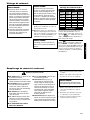
Whenever the unit will not be used for 30
days or longer, use the following proce-
dures to prepare it for storage:
Clean external parts thoroughly.
Ŷ
Drain all the fuel from the carburetor Ŷ
and the fuel tank.
To do so:
Prime the primer bulb until no more 1.
fuel is passing through.
Start and run the engine until it 2.
stops running.
Repeat steps 1 and 2 until the engine 3.
will no longer start.
Long Term Storage
Remove the spark plug and pour about Ŷ
1/4 ounce of 2-cycle mixing oil into the
cylinder through the spark plug hole.
Slowly pull the recoil starter 2 or 3
times so oil will evenly coat the interior
of the engine. Reinstall the spark plug.
Before storing the unit, repair or
Ŷ
replace any worn or damaged parts.
Remove the air cleaner element from
Ŷ
the carburetor and clean it thoroughly
with soap and water, let dry and reas-
semble the element.
Store the unit in a clean, dust-free area.
Ŷ
IMPORTANT!
All stored fuels should be stabilized with a
fuel stabilizer such as STA-BIL.
CAUTION!
Gasoline stored in the carburetor for
extended periods can cause hard start-
ing, and could also lead to increased
service and maintenance costs.
0XIÁHUDQGVSDUNDUUHVWHUPDLQWHQDQFH
NOTE
Damage caused by stale or contaminated
fuel is not covered by the Shindaiwa war-
ranty policy.
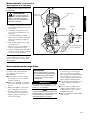
Engine Cover
Screws
Engine Cover
0XIÀHU
0XIÀHU*DVNHW
0XIÀHU%ROWV
Spark Arrester Screen
Spark Arrester Cover
Cover Screws
With a 3 mm hex wrench remove the 1.
4 engine cover screws and the engine
cover.
If the engine becomes sluggish and low
on power, check and clean the spark
arrester screen.
IMPORTANT!
If you note excessive carbon buildup, con-
sult with an authorized servicing dealer.
WARNING!
Never operate the unit with a
GDPDJHRUPLVVLQJPXIÀHURUVSDUN
arrester! Operating with a missing or
GDPDJHGVSDUNDUUHVWHULVD¿UHKD]DUG
and could also damage your hearing.
With a 4 mm hex wrench, remove the 3 2.
muffler bolts and the muffler.
With a small flat bladed screwdriver 3.
remove the 2 screws holding the
spark arrester screen and cover to the
muffler.
Remove the screen and clean it with a 4.
stiff bristle brush.
Inspect the cylinder exhaust port for 5.
any carbon buildup.
Reassemble the spark arrester, muffler 6.
and engine cover in the reverse order
of disassembly.

18
NO
NO
NO
NO
NO
YES
YES
YES
YES
YES
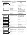
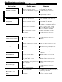
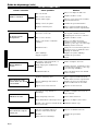
Troubleshooting Guide
Does the engine crank?
Good compression?
Does the tank contain
fresh fuel of the proper
grade?
Is fuel visible and moving
in the return line when
priming?
Is there spark at the spark
plug wire terminal?
Check the spark plug.
The plug is damaged internally or of the
wrong size.
What To Check Possible Cause Remedy
ENGINE DOES NOT START
Faulty recoil starter.
Fluid in the crankcase.
Internal damage.
Loose spark plug.
Excess wear on cylinder, piston,
rings.
Fuel incorrect, stale, or contaminated;
mixture incorrect.
Check for clogged fuel filter and/
or vent.
The ignition switch is in “O” (OFF)
position.
Shorted ignition ground.
Faulty ignition unit.
If the plug is wet, excess fuel may be in
the cylinder.
The plug is fouled or improperly gapped.
Consult with an authorized servicing
dealer.
Tighten and re-test.
Consult with an authorized servicing
dealer.
Refill with fresh, clean unleaded gasoline
with a pump octane of 87 or higher
mixed with a premium 2-cycle mixing oil
or with an equivalent high quality 2-cycle
mixing oil.
Replace fuel filter or vent as required.
Restart.
Move switch to “I” (ON) position and
restart.
Consult with an authorized servicing
dealer.
Crank the engine with the plug removed,
reinstall the plug, and restart.
Clean the spark plug. Check the
Specifications section for the correct plug
and gap for your unit. Restart.
Replace the spark plug. Check the
Specifications section for the correct plug
and gap for your unit. Restart.

19
Troubleshooting Guide (continued)
Operator is overworking the unit.
Carburetor mixture is too lean.
Improper fuel ratio.
Fan, fan cover, cylinder fins dirty or
damaged
Carbon deposits on the piston or in the
muffler.
Clogged air cleaner element.
Loose or damaged spark plug.
Air leakage or clogged fuel line.
Operate at slower rate.
Consult with an authorized servicing
dealer.
Refill with clean fresh unleaded gasoline
with a pump octane of 87 or higher, mixed
with a premium 2-cycle mixing oil at a 50:1
gasoline/oil ratio.
Clean, repair or replace as necessary.
Consult with an authorized servicing
dealer
Clean or replace the air filter
Tighten or replace the spark plug.
Restart. Check the Specifications section
in this manual for the correct spark plug
for this unit.
Repair or replace fuel filter and/or fuel
line.
Water in the fuel.
Piston seizure.
Faulty carburetor and/or diaphragm
Overheating condition.
Improper fuel.
Carbon deposits in the
combustion chamber.
Check fuel octane rating; check for
presence of alcohol in the fuel. Refuel as
necessary.
Consult with an authorized servicing
dealer.
Refill with fresh fuel/oil mixture.
Consult with an authorized servicing
dealer.
Consult with an authorized servicing
dealer.
Is the engine overheating?
Engine is rough at all
speeds. May also have black
smoke and/or unburned
fuel at the exhaust.
Engine is knocking.
LOW POWER
What To Check Possible Cause Remedy
Valve clearance set incorrectly.

20
ADDITIONAL PROBLEMS
Fuel tank empty.
Clogged fuel filter.
Water in the fuel.
Shorted spark plug or loose terminal.
Ignition failure.
Piston seizure.
Ground (stop) wire is disconnected or
switch is defective
Overheating due to incorrect spark plug
Clogged air filter.
Clogged fuel filter.
Lean fuel/air mixture.
Idle speed set too low.
Switch turned off.
Refuel. See Fuel section of manual.
Replace fuel filter.
Drain; replace with clean fuel. See Fuel
section of manual..
Clean or replace spark plug. Check the
Specifications page in this manual for the
proper spark plug for your unit. Tighten
the terminal.
Replace the ignition unit.
Consult with an authorized
servicing dealer
Test and replace as required.
Replace the spark plug. Check the
Specifications page in this manual for the
proper spark plug for your unit.
Clean or replace the air filter.
Replace the fuel filter.
Consult with an authorized
servicing dealer.
Adjust idle. Check Specifications page for
correct idle speed.
Reset the switch and re-start.
Overheated engine.
Engine idle too high.
Broken clutch spring or worn clutch
spring boss.
Loose attachment holder.
Warped or damaged attachment.
Loose gearcase.
Poor acceleration.
Engine stops abruptly.
Engine difficult to
shut off.
Cutting attachment
moves at engine idle.
Excessive vibration.
Cutting attachment will
not move.
Idle engine until cool.
Adjust idle. Check Specifications page for
correct idle speed.
Replace spring/shoes as required,
check idle speed.
Inspect and re-tighten holders securely.
Inspect and replace attachment
as required.
Tighten gearcase securely.
Bent main shaft/worn or damaged
bushings.
Shaft not installed in powerhead or
gearcase.
Broken shaft.
Damaged gearcase.
Inspect and replace as necessary.
Inspect and reinstall as required.
Consult with a authorized
servicing dealer.
Troubleshooting Guide (continued)
What To Check Possible Cause Remedy
Valve cover is leaking. Consult with an authorized
servicing dealer.
Top of engine is getting
dirty and oily.
Idle set too high. Adjust idle. Check Specifications page for
correct idle speed.
Engine will not
idle down.
Engine has an air leak. Consult with an authorized servicing dealer.
Page is loading ...
Page is loading ...
Page is loading ...
Page is loading ...
Page is loading ...
Page is loading ...
Page is loading ...
Page is loading ...
Page is loading ...
Page is loading ...
Page is loading ...
Page is loading ...
Page is loading ...
Page is loading ...
Page is loading ...
Page is loading ...
Page is loading ...
Page is loading ...
Page is loading ...
Page is loading ...
Page is loading ...
Page is loading ...
Page is loading ...
Page is loading ...
Page is loading ...
Page is loading ...
Page is loading ...
Page is loading ...
Page is loading ...
Page is loading ...
Page is loading ...
Page is loading ...
Page is loading ...
Page is loading ...
Page is loading ...
Page is loading ...
Page is loading ...
Page is loading ...
Page is loading ...
Page is loading ...
Page is loading ...
Page is loading ...
Page is loading ...
Page is loading ...
Page is loading ...
Page is loading ...
Page is loading ...
Page is loading ...
Page is loading ...
Page is loading ...
Page is loading ...
Page is loading ...
-
 1
1
-
 2
2
-
 3
3
-
 4
4
-
 5
5
-
 6
6
-
 7
7
-
 8
8
-
 9
9
-
 10
10
-
 11
11
-
 12
12
-
 13
13
-
 14
14
-
 15
15
-
 16
16
-
 17
17
-
 18
18
-
 19
19
-
 20
20
-
 21
21
-
 22
22
-
 23
23
-
 24
24
-
 25
25
-
 26
26
-
 27
27
-
 28
28
-
 29
29
-
 30
30
-
 31
31
-
 32
32
-
 33
33
-
 34
34
-
 35
35
-
 36
36
-
 37
37
-
 38
38
-
 39
39
-
 40
40
-
 41
41
-
 42
42
-
 43
43
-
 44
44
-
 45
45
-
 46
46
-
 47
47
-
 48
48
-
 49
49
-
 50
50
-
 51
51
-
 52
52
-
 53
53
-
 54
54
-
 55
55
-
 56
56
-
 57
57
-
 58
58
-
 59
59
-
 60
60
-
 61
61
-
 62
62
-
 63
63
-
 64
64
-
 65
65
-
 66
66
-
 67
67
-
 68
68
-
 69
69
-
 70
70
-
 71
71
-
 72
72


Shindaiwa AHS2510 User manual
- Category
- Power hedge trimmers
- Type
- User manual
- This manual is also suitable for
Ask a question and I''ll find the answer in the document
Finding information in a document is now easier with AI
in other languages
- français: Shindaiwa AHS2510 Manuel utilisateur
- español: Shindaiwa AHS2510 Manual de usuario
Related papers
-
Shindaiwa 89310 User manual
-
-
-
-
-
-
-
-
-
Other documents
-
Makita HTR5600 User manual
-
 GARDEO PRO GTHT26RH-BAG Owner's manual
-
Ryobi RYAHT99 Owner's manual
-
Ryobi RYHDG88VN Owner's manual
-
Swisher E4-S3000 User manual
-
Dolmar HT-2249 D User manual
-
-
-
Honda SSHHSA Hedge Trimmer User guide
-
