Craftsman 358.799211 Owner's manual
- Category
- Power tools
- Type
- Owner's manual
This manual is also suitable for

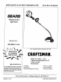
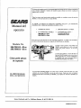
IMPORTANT MANUAL
Do Not Throw Away
8E_A/_S
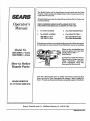
Operator's
Manual
Model No.
358.799211
_k WARNING:
Read the Operator's Manual and
FollowAH Warnings and Safety
Instructions. Failure To Do So
Can Result in Serious Inju_.
Always Wear Eye Protection
8E/_,_8/C RI:1FT$MI:1N_o
21cc GAS WEEDWACKER
2 Cycle Engine
* Assembly
e Operation
Fuel Mix 40:1
• Maintenance
• Repair Parts
. Sears, Roebuck and Co,, Hoffman Estates, IL 60179 USA
530--082430-05/24/94 © 1994, Sears, Roebuck and Co.

i ii ii i i , ii ,,i, ,,i,i1,,,111111ii , • . _ _ i _
[ i ,,,, , , ,,,,,,,
up_ tlmo_rati_a_d_instruct_intlmapera_r'a mam_ Searsw'-lIx_ _ eamrg_any_ec_
in _ or worxmansmp [;_1
This warrantye=ludes the blade, nylon lizze,sparklxlua and airf_e_; wh_h areexpenda_ _rts andbe_on_ worn dur_
uorm_use _
w_r_s_c_ _ Av_"_ _ _G _ _SswAC_ ro_ _-_r_s___ H
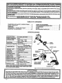
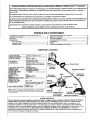
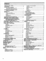
TABLE OF CONTENTS
WARNINGS AND SAFETY INSTRUCTIONS ... 3
KNOW YOUR UNIT .......................... 5
ASSEMBLY .................................. 6
OPERATION -- Fueling Your Engine .......... 9
STARTING YOUR ENGINE ................... 10
USING YOUR TRIMMER ..................... 11
CUSTOMER RESPONSIBILITIES ............ 15
ACCESSORIES ............................. 19
INDEX ..................................... 20
ILLUSTRATED PARTS LIST ................. 21
SPECIFICATIONS
ENGINE TYPE:
DISPLACEMENT:
ENGINE RPM:
i,,,,, ,,, , ,
IGNITION:
IGNITION TIMING:
CARBURETOR:
,,,, ,,,,, ,
ENGINE "OFF":
STARTER:
UF LER:
CUTTING PATH:
FUEL TANK:
i ,,,,,,,,,,,,,,,i
SPARK PLUG:
SPARK PLUG GAP:
, ,,,, ,,, ,, ,,
MODULE AIRGAP:
LUBRICATION:
CUTTING LI_:
!21cc
Operating---8000
SolidState
Spark Advance --
Nonadjustable ,
Diaphragm All Position With
Adjustable Fuel _e Jet
Positive Switch
Auto Rewind
Temperature Limiting
15"
,,_0cc
Champion (CJ' 14)
.025"
.01o" to:'0'i4"
Gasoline/OilMixture-
(see "Fuelin GYour Engine')
.080" diameter line
MANUFACTURED UNDER O_E OR MORE OF T_E _O_OW_O US. PATE_rrS_
_S.AND FOREIGN PATENTS PENDING.
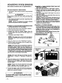
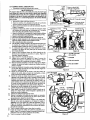
FUEL
CAP
ASSIST
HANDLE
SPARK PLUG
SWITCH _'_
STARTER
ROPE
SAFETY LABEL
DRIVESHAFT
HOUSING
SHIELD
AIRFILTER
SERIALNUMBER
AND STARTING
INSTRUCTIONS
LIMITE_
TRIMMER HEAD
]]luvixatio_may differfrom a_tml model due to d_n _.
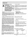
_j SPECIAL NOTICE
For users on U.S. Forest Land and in some states, tncludf:ug Califor_ia(PubHc Resources Codes 4442 and 4443),
_] Idaho, Maine, Minnesota, New Je ._e_ Oregon, and Washingtom Certain. internal combustion engines operated.on for-
|_ _ brush, and/or grass-covered land m the above areas _ required to be equip _pgdw_th a spark arresto_ maintained m etlec- [_
tire working order, or the engine must be constructed,.eqmppe_ and maintaine_ for the prevention of fire. Check vnth your . _]
[_ stateorlocalauthoritiesforregulationspertalnin_totheserequirements.Failuretofollowthesere_tiremer_tsisa violationof
the law. This unit isnot factory--equipped w_th a spark arrestor;,however,a sparkarrestorisavailableas_ optional
part. If a spark arrestor is required in your area, contact your SEAR_ Service Center/Department for the correct kit.

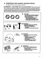
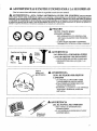
A WARNINGS AND SAFETY INSTRUCTIONS
(See Adch'tional Safety Instructions throughout this Manual)
WARNING - THIS POWER TOOL CANBE DANGEROUS! This unit can cause serious
injury or blindness to the operator and others. The warnings and safety instructious in this manual must be fol-
lowed to provide reasonable s_'ety and efficiency in using this unit. The operator is responsible for following the
warnings and instructions in this manual and on the unit. Read the entire Operator's Manual before assem-
bling and using this unit! Restrict the use of this power tool to persons who read, understand and
follow the warnings and instructions in this manual and on the unit.
QOQ
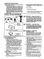
A
DANGER
BLADES OR SLINGING HEADS
CAN COME OFF AND CAUSE
SERIOUS INJURY.
- THIS UNIT IS DESIGNED FOR
LINE TRIMMER USE ONLY
- NEVER USEANY OTHER CUTTING
ATTACItME_T WITH THIS UNIT,
L_gG_d_ _ Thro A
W.AA_qNG
OBJECTS VIO_NTLY.
'_ - YOU CAN BE BLINDED OR
INJURED.
• d Boots - WEAR EYE AND LEG PROTECTION.
60 Foot
(20 meters)
t/ Hazard Zone
_k WARNING
HAZARD ZONE FOR THROWN
OBJECTS
- TRIMMER LINE CAN THROW
OBJECTS VIOLENTLY.
- OTHERS CAN BE BLINDED
OR INJURED,
- KEEP PEOPLE AND ANIMALS
30 FEET (10 METERS) AWAY.
Operator's
Manual
Safety
Labels
_k WARNING
READ OPERATOR'S MA_vTJAL.
- FOLLOW ALL WARNINGS AND
INSTRUCTIONS.
- FAILURE TO DO SO CAN RESULT
IN SERIOUS INJUR_
-3-

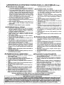
WARNINGS AND SAFETY INSTRUCTIONS....(Continued)
A OPERATOR SAFETY
• Always wear safety eye protection.
• Always wear long pants, Iong sleeves, boots and
gloves. Wearing safety leg guards is recom-
mended. Do not go barefoot or wear sandals, jew-
ehT, short pants, short sleeves, loose clothing, or
clothing with loosely hanging ties, straps, tassels,
etc.; they can be caught in moving parts.
•. Secure hair so it is above shoulder length.
• Do not operate this unit when you are tired, ill, or
under the influence of alcohol, drugs, or medica-
tion.
• Wear hearing protection if"you use this unit for
more than 1-1/2 hours per day.
• Never start or run the engine inside a closed room
or building.BreathingexhaustRnnes can kill.
• Keep handlesfreeofelland fuel.
A UNIT/MAINTENANCE SAFETY
* Look forand replacedamaged or loosepartsbe-
foreeachuse.Look forand repairfad leaks before
use.Keep the unitingood working condition_
• Replacetrimmer head parts that are chipped,
cracked,broken,ordamage in any otherway be-
foreusingthe unit.
* Use only SEARS .08,0" diameter line. Never use
wire, rope, string, etc.
• Make sure the unit is assembled correctly as listed
in this manual.
• M_e carburetoradjustmentswith thelower end
supportedtopreventthe trimmer linefrom con-
tactingany object.
• Keep othersaway when making carburetorad-
justments.
• Disconnect the spark plug before performing
maintenanceexceptcarburetoradjustments.
• Use onlygenuineSEARS accessories and replace-
ment parts as recommended for this unit.
A FUEL SAFETY
• Mix and pour fuel outdoors.
• Keep away from sparks or flames:
• Use a containerapproved forfuel.
• Do not smoke or allowsmoking near fuelor the
unitorwhileusingtheunit.
• Wipe up allfuelspillsbeforestextingengine.
• Move atleastI0feet(3meters)away fromfueling
sitebeforestartingengine.
• Stopengineand allowunittocoolbeforeremov-
ingfuelcap.
• Empty thefueltankbeforestoringtheunit.Use
up fuelleftinthe carburetorby startingtheen-
gineand lettingtheenginerun untilitstops.
• Store unit and fuel in an area where fuel vapors
cannot reach sparks or open flames from water
heaters, electric motors or switches, fiLrnaces, etc.
A CUTTING SAFETY
• Inspect the area to be cut before each usc. Remove
objects (rocks, broken glass, nails, wire, string,
etc.) which can be thrown or become entangled in
the trimmer head.
• Keep others including children, animals, bystand-
ers and helpers outside the 60 foot (20 meter) Haz-
ard Zone. Stop the engine immediately if you are
approached.
• Always keep the engine on the fight-hand side of
your body.
• Hold theunit firmly with beth hands.
• Keep firm footingand balance.Do not over-
reach.
• Keep thetrimmer head belowwaistlevel.
° Do notraisethe engineaboveyourwaist.
• Keep allpartsofyour body away from trimmer
headand mufflerwhen engineisrunning.
• Cut from your right to your left.
• Use only for jobs explained in this manual.
A TRANSPORTING AND STORAGE
• Stop the unit before carrying.
° Keep the muffler away from your body.
* Allowthe engine to cool,and securetheunitbe-
forestoringortransportingina vehicle.
* Empty the fueltank beforestoringortransport.
ingtheunit.Use up fuelleftinthecarburetorby
startingtheengineand lettingtheenginerun un-
tilitstops.
• Store unit and fuel in an area where fuel vapors
cannotreach sparks or open flamesfrom water
heaters, electric motors or switches, furnaces, etc.
• Stere unit so linelimitercannot accidentally
cause injury. The unit can be hung by the bracket
below the engine or by drive shaft housing.
• Store the unit out of the reach of children.
If situations occur which are not covered in this manual, use care and goodjudgment.
[/'you need assistance, contact your Authorized Service Dealer or the
CUSTOMER ASSISTANCE HOTLtNE, 1-800-235-5878.
SAFETY NOTICE
Exposure t.o.vibrati_nsthr_ughpr_.ngeduse_fgas_inep_eredhandto_sc_u_dcauseb_dvesse_rnerve [_
aama_e m erie tzngers,_hands, and wr_s.ts of people prone to circulation disorders or abnormal swe_gs. Pro- [_
,ongect us$ m cola wea[ner has t_een_llnked to blood vessel damage in otherwise healthy people. If symptoms [_i
_su?n .as numbness, pare: loss of _s_. ngth, change m s k_. color or texture, or loss of feelingln the fingers, [_
arias or wrts_s, axe. onrmue .r_e use o_ _ tool and seek medical attention. An anti-vibration system does not [_
guarflnree..r_eavo,aa_tceo_ r_ese prot)tems.. Users who opex_tte power tools on a continual and regular basis [_
m_ member ctosety their pnystcat con_tion and the condition of this tooL _]
-4-

I I I I IIII II IIII II IIIIIIIIIIII IIIIIIHI
III I I I IIII I • I I I I ,,I,l_llllll,l,iiIIIII I _ • | | I I II I I' [ II | i I IIII
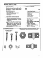
KNOW YOUR UNIT
i i i iii iiiiii i iiii ii | i
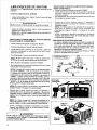
A. C. CARTON CONTENTS
fill IIII I I I I I
INTRODUCTION
Your Trimmer is a versatile product developed for
large lawns and to make short work era variety of
lawn care tasks -- trimming, scalping, mowing,
and sweeping.
Special Features Include:
• 15" Cutting Path
• Semi-Automatic Trimmer Head
• Adjustable Assist Handle
• 2lee Engine
KEY
NO. QTY
B. UNPACKING INSTRUCTIONS
L After removing the contents from the car_n,
check parts against the Carton Contents list.
2. Examine the parts for damage. Do not use
damagedparts.
3. NetifyyourSEARSStoreimmediatelyifapart
is missing or damaged.
Your unit has been shipped with a plastic
shipping guard over the primer bulb (see
"Specifications" for location). Remove and
discardthe plastic shipping guarcL
It is normal to hear the fue! falter rattlein
an empty fuel tank.
• Engine/Trigger Housing 1
• Drive Shai_ Assembly w/Safety Label 1
• Shield 1
• Trimmer Head 1
• Assist Handle 1
• Operator's Manual I
• Loose PartsBag i
B.
C.
D.
E.
E
G.
H.
I.
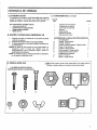
LOOSE PARTS BAG CONTENTS:
Hex Wrench 1
Screw - Nose Cone 2 *
Screw - Shield 2
Square Head Screw - Assist Handle 1
Nut - Nose Cone 2 *
Washer - AssistHandle 1
W'mg Nut - AssistHandle 1
Dust Cup - DriveShaftHousing i
Bracket - Shield !
Bracket - Assist Handle 1
D. HAP_DWARE CHART
HARDWARE SHOWN
ACTUAL SIZE
]XOL]_: This Hardware is packaged in the Plastic ]_g. Refer
to the Hardware reference letters below during assembly.
A. B. C.
D. E. E
G.
I°
H,
-5-

ASSEMBLY
(If tool is received assembled, repeat all steps in this section to be sure assembly is correct and is ad-
justed for the operator.)
A. PREPARATION
This Oparator's Manual is designed to help you as-
semble the tool and to provide its safe operation. It is
important that you read the entire manual to become
familiarwiththe toolbe/oreyou beginassembly.If
you have any _estions or need _er assistance,
callour CUSTOMER ASSISTANCE HOTLINE at
1-800-235-5878.
,,,,,,,,,,,,,.,,,,, i ,,,,,,.,,
1.Read your Operator's Manual
2.Tools you willneed:
- Hex Wrench providedwiththetool.
- AdjustableWrench
- Standard Screwdriver
- PhillipsScrewdriver
i l ii
Hardware referred to in the following sections
is shown actual size in the Hardware Chart, page 5.
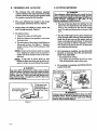
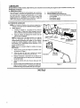
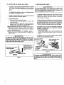
I. TUBE (Figure 1 )
a. InsextscrewsA. and nuts D. inthe nosecone.
Figurei. Tightenwith the hex wrench (pro-
vided)justenough toheldpartstogether.
b. Remove thepacking coverfrom the straight
end of the tube if so equipped.
Make sure the drive shaft does not fall out
of the tube. Dirt on the shaft will significantly re-
duce the life of the tool. If the drive sha_ falls out
ofthe hous_ dean, re-lubricate,and re-ins-
tal!.See the Drive ShaftLuhricatlon" section.
Before performingstep c., it might be nec-
essary to loosen the throttle grip screws.
c. Insert the tube through the throttle grip as
shown in Figure 1.
d. Align the groove on the tube with the ridge on
the inner, lower wall of the nose cone opening.
Figure 1.
e. Firmly push the tube into the nose cone open-
ing until the bold Rue on the decal is not vis-
ible. Make sure the drive shaft is eng_ed by
pulling the starter rope; if the arbor shaft does
not turn, reinstall the tube in the nose cone.
fi Tighten the nose cone screws until secure.
g. Slide the throttle grip toward the engine until
it contacts the nose cone. Then, tighten the
throttle grip screws until secure.
Drive
Shaft
BoldLine
On Decal
Throttle
Grip
/
Nose Cone Ridge
Groove
Throttle
Nuts D. Cable
Tube
Arbor
ShafL----_
Figure i
NOTES
-6-

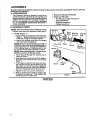
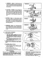
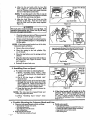
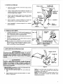
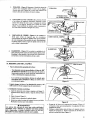
2. ASSIST HANDLE
w Insert the end of the tube through the assist han-
dle. Figure 2 (inset).
b. Align the v.ssist handle between the safety label
and the throttle trigger housing. Seat tube in the
groove in the assist handle. Figure 2.
Co
d_
Insert the tab on bracket I. into the slot on the as-
sist handle. Figure 2. Then, lay the bracket into
place over the tube.
Insert screw C. down through the hole in the assist
handle bracket and then through the assist han-
dle. Figure 2.
e. Assemble washer E. and wing nut E onto the
screw. Tighten securely.
Assist Handle
Figure 2
Handle
Screw C.
3. 'rRI313_R HEAD
v. Placethe dust cup "G._ over the hex nut on the
bottom ofthetube.Figure3. The hexnut should
fitcompletelyinsidethe dustcup.
b. Hold thedustcup withawrench tokeepthearbor
shaftfrom turning.
c. Thread the trimmer head onto the arbor shaft
againstthe dustcup and hand tightenfirmly_
NOTE: Unless trimmer head istightenedade-
quately,itcan:unthreadwhen engineisstartedor
stopped. Ifthissituationoccurs,reinstallthe
trimmer head and tightenmore securely.
H-- i
Nut --'P
Dust
CupG.
Direction
toI_t_1
Use awrenchto k_p the
shaftfrommmingwhile
spinning the trimmer
headonto the unit.
Figure 3
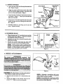
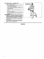
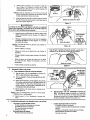
4. SHIELD ATTACHMENT
tisequipped_tk a_b!l_ter which cutsexcess_ I
[Iinb: t°: thei_proP_'iIeng th_:: !,: ': I
Hole m tube
[ CAUTION: IThe line limlter (on the underside of
the shield) is sharp and can cut you.
a. Match the tab on bracket "H." with the hole in the
tube.
b. Attach the shield to the bracket with the two
screws "B." Tighten evenly and securely.
Figure 4
NOTE: Although a screwdriver slot is pro-
vided in screws "B. ", it is easier to install the
screws with a wrench or socket.
NOTE: It is possible that a small space will be
left between the bracket and the shield when
the screws are fi_y tightened.

5. OPERATING POSITION
a. Before starting the engine, stand as shown in "
Figure 5 and check for the following:
1. Left arm fully extended_ hand holding assist
handle.
2. Right arm slightly bent, hand holding throttle
grip,fingerson throttletrigger.
3. Engine below waistlevel
4. Weight of toolevenly distributedbetween
5. Without operatorbending over,the trimmer
head isnearand paralleltotheground andeas-
ilycontacts the material to be cur.
When adjustingthe assist handle for
comfort, be sure that the assist handle remains
between the trigger housing and the safety la-
bel. Figure 2.
b. Adjust assist handle up or down the tube (but
above the safety labels) to a comfortable position.
e. Rotate assist handle from left to right to tilt the
s_ngle of the trimmer head when cutting a large,
oped area such as a ditch bank.
,,,,,,,,,,,,,,,,,, ..................
NOTES
OPERATING
POSITION
-8-

IIII I • I I IIIL I
IIII II III i I I I I I
FUELING YOUR ENGINE
ii ii i .......
BEFORE FUELING ENGINE:
A WARNING
Be sure to read the fuel safety information in the Warn-
ings and Safety Instructions section on page 4 of this
manual before you begin.
l Ifyou do not understand the fuel safety section DO NOT
attempt to fuel your unit; seek help from someone that
does understand the fuel safety section or call the Cus-
tomer Assistance Hotline at 1-800-235-5878.
GASOLINE
The two-cycle engine on this product requires a fuel mix-
ture of regular unleaded gasoline and a high quality en-
gine oil for lubricationofthe bearings and othermoving
parts.The correctfuel!oilmixture is40:1(seeFuel Mix-
tureChart). Too 1ittte oil or the incorrect oil type will
cause poor performance and maycausethe engine to over-
heat and seize.
Gasolineand oilmust be premixedinacleanapprovedfuel
container.Always use freshregularunleadedgasoline.
IMPORTANT:. Experience indicates that alcohol
blended fuels called gasohol (or using ethanol or meth-
anol) can attract moisture, which leads to oil/gas sepa-
ration and formationofacidsduring storage.Acidic
gascan damage the fuelsystem ofan enginewhile in
storage.To avoidengineproblems,the fuelsystem
shouldbe emptiedbeforestoragefor30 daysorlonger.
Drainthegastank,thenrun thefuelout ofthecarbure-
torand fuellinesby startingthe engineand lettingit
run untilitstops. Use freshfuelnext season. See
STORAGE instructionsfor additionalinformation.
Neveruseengineorcarburetorcleanerproductsinthe
fueltank orpermanent damage may occur.
FUEL STABILIZER
Fuel stabilizer is an acceptable alternative in minimizing
the formationoffuelgum depositsduring storage.Add
stabilizerto gasolinein fueltank or storagecontainer.
Always followthe fuelmix ratiofound on thestabRizer
container.Run engine at leastI0 minutes afteradding
stabilizertoallowthe stabilizertoreach thecarburetor.
Youdo nothavetodrainthefueltankforstorageifyouare
usingfuelstabilizer.
CRAFTSMAN 40:1 2 cycle engine oil is specially blended
with fuel stabilizers. If you do not use this Sears oil, you
can add a fuel stabilizer (such as CraRsman No. 33500) to
yourfuel tank.
2-CYCI OIL:
CRAFTSMAN 40:12 cycleoilisstronglyrecommended.
This oilis speciallyblended with fuelstabilizersfor
increased fuel stability (extends fuel life up to 5 times
longer) and reduced smoke.
If CRAFTSMAN 2 cycle oil is not available, use a good
quality 2 cycle AIR-COOLED engine oil that has a
recommended fuel mix 40:1.
IMPORTANT! Do not use:
• AUTOMOTIVE OIL
* BOAT OILS (NMMA, BIA. etc.)
These oils do not have proper additives for 2-cycle,
AIR-COOLED engines and can cause engine damage.
GASOLINE ANDOIL'MIXTURE
Mix gasoline and oil as follows:
* Consult chart for correct quantities.
* Do notmixgasolineandoildirectlyinthefueltank_
FOR ONE GALLON:
• Pour 3.2 ounces of ldgh quality, 2-cycie engine oll
into an empty, approved one gallon gasoline con-
tainer,
• Add one gallonofregularunleadedgasolinetothe
galloncontainer,then securelyreplacethe cap.
Shake the containermomentarily.
• The mixture isnow ready foruse. Fuelstabilizer
can be added atthistime ifdesired;followmixing
instructionson the label.
1W_L MIXTURE CHART
40:1 Fuel:Oil Mix Ratio
Ga_line Oil (fl. oz.)
1 gallon 3.2
1.25 gallons 4.0
2.5 gallons 8.0

STARTING YOUR ENGINE
(For location of controls, refer to "Speclfieatiozls.")
BEFORE STARTING THE ENGINE:
• Fuel engine. Move 10 feet (3 meters) away from fuel-
ing site.
f A WARNING
The trimmer head will turn while starting the
e_ #i_.
• Rest engine and shield on ground, supporting trim-
mer head off ground.
Remove and discard the plastic shipping
guard on the primer bulb (if so equipped).
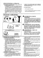
STARTING A COLD ENGINE OR WARM ENGINE
AFTER RUNNING OUT OF FUEL:
• Move the choke lever to the "Full Choke" position.
• Slowly press the primer bulb 6 times.
• Squeeze and hold the throttle trij_ger. Keep the
throttle trigger fully squeezed _ntil the engine lwns
smoothly.
• Pull starter rope sharply 5 times.
The eng_e may sound as if it is trying to
start before the 5rn pull If so, go to the next step im-
mediately
• Move the choke lever to the "Half Choke" position.
• Pull the starter rope shanty until the engine runs,
but no more than 6 pulls.
Iftheenginehas notstartedafter6pulls(at
halfchoke),checktomake surethechoke leverisin
the properposition.Then, move the choke'leverto
the"FullChoke" positionand presstheprimerbulb6
times;squeezeand holdthethrottletriggerand pull
thestarterrope2 more times.Move theChoke lever
to "Half Choke _and pull the starter rope until the en-
gine runs, but no more than 6 more pulls.
Iftheenginestillhas not started,itisprob-
ablyflooded.Proceed to "Startinga Flooded En-
gine."
Allow the engine to run 15 seconds, then move the
choke lever to "OffChoke." Allow the unit to run for
30 more seconds at "Off Choke _ before releasing the
throttle trigger.
If engine dies with the choke lever at the"Off
Choke" position, move the choke lever to "Half
Choke" and pull the rope until the engine runs.
To stop the engine, push and hold the momentary
switch in the "Off" position; do not release until the
engine has completely stopped.
l A WARNING
Avoid any bodily contact with the muffler when
starting a warm engine. A hot muffler can cause
serious burns.
STARTING A WARM ENGINE THAT HAS NOT
RUN OUT OF FUEL:
• Move the choke lever to the "I-IalfCh0ke" position.
• Squeeze and hold the throttle .l_igger. Keep the
throttle trigger fully squeezed un_ t_ engine runs
smoothly.
• Pull starter rope sharply until engine runs, but no
more than 5 pulls.
• Allow the engine to run 15 seconds, then move the
choke lever to "Off Choke.
If engine has not started, pull starter rope 5
more pulls. Ii_engine still does not run, it is probably
flooded. Proceed to "Starting a Hooded Engine. _
• To stop the en_ine, push and hold the momentary
switch in the "Off' position; do not release until the
engine has completely stoppe&
STARTING A FLOODED ENGINE:
Flooded engines can be started by placing the choke
lever in the "Off Choke" position; then, pull the rope
to clear the engine of excess fuel This could requh'e
pulling the starter rope many times depending on
how badly the unit is floode_
If the unit still doesn't start, call the Customer Assis-
tance Hotline at 1-800-235-5878.
ISTART£NGPOSmON I
Momentary Choke
Switch
Figure 6
Primer
Bulb
Choke
Lever
- 10-

OPERATING INSTRUCTIONS
Bring the engine to cutting speed before entering
the material to be cut.
• Do not run the engine at a higher speed
than necessary. The cutting line will cut effi-
_hrottentlywhen the engine is run at less than full
le. At lower speeds, there is less engine noise
and vibration. The cutting llne will last longer
and will be less likely to "weld" onto the spool.
• If the trimmer head does not turn when the
engine is in operation, make sure the tube is
properly seated in engine shrou& Refer to "As-
sembly-Tube."
i nail iiiiiiii
USING YOUR TRIMMER
• Alwa_s release the throttle trigger and al-
low the engine to return to idle speed when
not cutting.
• To stop engine:
• Release the throttle t_ggex.
• Push and hold down the momentery switch
until the engine has stopped completely.
i ii
t9
n ..
Face Boots
Shield
.L I
(20 meter)
_._30_ _ Hazard Zone
ii ,11 i
Semi-Automatic Trimmer Head
(see Accessory List for part number)
Replacement Parts
A
WARNING- THROWS OBJECTS
The rapidly moving line causes objects to be
thrown violently. The shield will not provide
complete protection to the operator or others.
_e operator must wear a safety face
shield or goggles. Always wear heav_
longpants and boots. Keep others at Ieast
30 feet (10 meters) awa_
WARNING - HAZARDZONE
This tool will throw objects and cut. Keep oth-
ers including children, animals, bystand-
ers end helpers at least 30 feet ( 10 meters)
away f_om the operator and tool. Stop
the engine if you are approached.
WARNING - DAMAGED
TRIMMERHEAD
Trimmer head parts that are chipped_ cracked
or damaged in any other way can fly apart and
cause serious injury. Do not use. Replace
damaged parts before using the tool
A. LINE TRIMMER SAFETY
1. OPERATOR SAFETY
a. Always wear safety eye protection.
b. Always wear long pants, boots, and gloves,
Wearing safety leg guards is recommended.
See _Accessories. _Do not go barefoot or wear
sand_, jewelry,shortpants, looseclothing,or
clotl_ng with looselyhanging ties,straps,or
tassels;theycan be-caughtinmoving parts.
c. Securehairso itisabove shoulderlength.
d. Do notoperatethisunltwhenyou aretired,ill,
or under the influenceof alcohol,drugs,or
medication.
e. Do notswing theunitwithsuch forcethatyou
are indanger oflosingyour balance.
f. Never startor run the engine insidea closed
room or building.Breathing exhaust fumes
can kiil.
g. Keep handlesfreeofoiland fuel.
2. TOOL SAFETY
a, Look forand replacedamaged or looseparts
beforeeach use.Look forand repairfuelleaks
beforeuse. Keep the unit in good working
condition.
b. Use only SEARS .080"diameter line.Never
use wire,rope,string,etc.
c. Make sure theunit isassembledcorrectlyas
listedinthismanual.
d. Make carburetora_justmentswiththe lower
end supported to prevent the trimmer line
fromcontactinganyobject.
e. Keep othersawaywhen making carburetorad-
justments.
f. Use onlySEARS accessoriesorattachmentsas
recommended.
3. C_G SAFETY
a. Inspect the area to be cut before each use. Re-
move objects (rocks, broken glass, nails, wire,
string, etc.) which can be thrown or become en-
tangled inthetrimmer head.
b. Always keep the engine on the right-hand
sideofyour body.
c. Hold the toolfLrmlywithbothhands.
d. Kee_ firmfootingand balance.Do not over-
rcaCIL
e. Keep the trimmer head belowwaistlevel.
f. Do not raisethe engineaboveyour waist.
g. When possible,cut with the leftsideof the
trimmer head.
h. Keep allpartsofyourbodyaway fromthetrim-
mer head and mufflerwhen engineisrunning.
i. Use only for jobs explained in this manual.
- 11 -

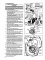
B. TRIMMER LINE ADVANCE
@
The trimmer line wilI advance approxi-
mately 2 inches each time the bottom of the
trimmer head is tapped on the ground with
the engine running at full throttle.
• The most efficient Hne length is the maxl-
mum length allowed by the line Hmiter.
• Always keep the shield in place when the
tool is being operated. Figure 7.
To Advance Line:
1. Operate the engine at full throttle.
2. Held the trimmer head parallel to and above
the grassy area.
3. Tap the bottom of the trimmer head tightly on
the ground one time. See Figure 7. Approxi-
mately 2 inches of line will be advanced with
each tap.
Always tap the trimmer head on a grassy
area. Tapping on surfaces such as concrete or
asphalt can cause excessive wear to the trim-
mer head.
If the line is worn down to two
inches or less, more than one tap will be re-
quired to obtain the most efficient line tength_
, ,,,,,,,,,,,vu,,,Lw, , ,,,,,,,,,
A WARNING
Use only .080"-diameter line. Other sizes of line
will not advance properly and can cause serious
injur_ Do not use other matemals such as wire,
string, rope, etc. Wire can break off during cue-
ring and become a dangerous missile that can
cause serious injury.
Line L/miter Cuts Line
To ProperI_ngt______
To Advance Line,
Tap Bottom Of
Trimmer Head On
Ground One Time.
Figure 7
C. CUTTING METHODS
p ..
A WARN G
I
Use nnmmm speed mad do not _owd the line [
when cutting m-oun .dhard objects (rock, _ravel, !
fence posts, etc), which van damage the trimmer |
head, become entangled m the line, or be[
thrown causing a serious hazard, i
The tip of the line does the cutting. You will
achieve the best performance and minimum line
wear by not crewdJ_g the line into the catting
areal The right and wrong ways are shown in Fig-
ure8.
The llne will easily remove grass and weeds
from around wails, fences, trees and flower
beds, but it also can cut the tender bark of
trees or shrubs and scar fences. To help avoid
damage especially to delicate vegetation or trees
with tender bark, shorten line to 4-5 inches and
use at less than full throttle.
For trimming or scalping, use less than full
throttle to increase llne life and decrease
head wear, especially:.
- duringlight dutycutting.
- near objects around which the llne can wrap
such as small posts, trees or fence wire.
• For mowing or sweeping, use full throttle for
a good clean job.
of the Line
Line Crowded Into
Work Area
WRONG
Figure 8
I ...... Aw q I
Always wear eye protection. Never lean over the
trimmer head. Rocks or debris can ricochet orl
be thrown into eyes and face and cause blind-[
ness or other serious injury. [
- 12-

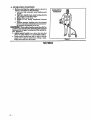
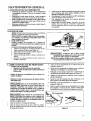
I. TRIMMING - Figure 9. Hold the bottom of
the trimmer head about 3 inches above the ground
and at an angle. Allow only the tip of the line to
make contact. Do not force the trimmer line into
the work are_
2. SCALPING- FIGUP_ 10. The scalpingtech-
nique removes unwanted vegetation. Hold the
bottom of the trimmer head about 3 inches above
the ground and at an angle. Allow the tip of the
line to strike the ground around trees, posts,
monuments, etc. This technique increases line
3. MOWING- Figure I1. Your trimmer is ideal
for mowing in places conventional lawn mowers
cannot reach. In the mowing position, keep the
line parallel to the ground. Avoid pressing the
head into the ground as this can scalp the ground
and damage the tool.
Above Ground v _,."
9
SCALPING
MOWING
Above Ground '
Figure 10
FIN 11
4. SWEEPING - Figure 12. The fanning action
of the rotating]ine can be used fora quick and easy
clean up. Keep the line parallel to and above the
surfaces being swept and move the tooI from side
to side.
i i iiiii i IIHIII
D. LINE REPLACEMENT
• For proper line feed:
- Use only genuine SEARS pre-wound
spools and .080" diameter line. The use of
other types of spools or lines can result in ex-
cessive breakage, line welding, and improper
line feed.
- .Pre-wound spools offer the most conven-
ient method for replacing Iine as well as
optimum performance.
• Always clean dirt and debris from the spool
and hub when performing any type mamte.
nance.
1. Installing Spool w/Line
a. Hold the Trimmer Head as shown in Fig-
ure 13. Press the two Lock Tabs and remove
the cover. Figure 13.
b. Remove the Spool. Figure 14.
c. Clean dirt and debris from all parts.
d. Inspect all Trimmer head parts for damage.
Replace damaged parts.
i WARNING i
Trimmer head parts that are chipped, cracked[
or .d_a_ed m any way can fly apart and cause[
serlot_s _njury. Do not use. Replace damaged[
par_s Dezore using the tool. [
SWEEPING
Figure 12
i
Lock Tab
Lock Tab
Figure 13
Hub
Figure 14
e. Catch the line in the notch in the spool. Fig-
ure 15 (inset). Leave about 4 inches of line
hanging from the spool.
fi Placeyour index finger over the line and notch
as shown in Figure 15. Insert the end of the
Line in the Line Exit Hole. Figure 15.
- !3 -

g. Align the line and notch with the Line Exit
Hole. Figuxe 15. Place Spool in Hub. Make
sure the Trimmer Line is not caught between
the rim of the Spool and the Hub.
N__QTFATo seat the spool in the Hub, it may be
necessary to pull the Linethrough the Line Exit
Hole until the spool drops into place.
h. Align the Lock Tabs on the Cover over the
Catches on the Hub. Push the Cover down
onto the Hub until the parts snap together.
Figure 16.
I A WARNING
The lock tabs must be latched onto the Hub, If[
installed incorrectl_ the Cover can fly off and]
become a dangerous missile. |
i. Check to make sure the Lock Tabs are properly
fastened as shown in Figure 16 (inset).
j. Obtain correct line length (4 inches) by press-
ing the Tap Button (Figure 17 ) and pulling on
the line agviu.
If tap button gets knocked out of the hub,
reassemble parts as follows:
• Remove the cover and spool.
• Place the spring in the hub cylinder. Fig-
ure 18 (inset).
• Place the tap button over the spring and hub
cylinder.
• Align the slotsin the tap button with the fins in
the base of the hub. Figure 18 (inset). Push
parts together.
• Reinstall the spool and cover.
Finger Over Notch
.Line Exit Hole
Figure 15
Catch
Figure 16
,ml ,,,
Approximately 2Inches ofLine Can BePulled _Fromthe
THmmer Head Each Time the Tap Button is 1"_.
Tap Button
Figure 17
Hub WmpoAs
Shown By
Rim
Fin In
Hub Base
2. Installing Line on Spool
a. To replace the Line on existing Spool:
1.) Follow "Installing Spool w/Line," steps
"_-d." and remove any line remaining on
the Spool.
2.) Use a 25 foot length of SEARS .080 _
diameter line.
3.) Insert about 1/4 inch of the end of the line
through the hole in the inner rim of the
Spool. Figure 18. A_ow no more than 1/2
inch of line to extend beyond the rim to
avoid interference with tapping action.
4.) "Wrapthe llne onto the spool as shown by
the arrow. Figure 18.
The Line must be wrapped firmly and
evenly for proper line feed.
5.) Follow "Installing Spool w/Line _ steps
Spool
b, If the Line breaks off or backs up in the
trimmer head, follow "Installing Spool w/
Line," steps "a.-d. Pull slack in Line until.
the Line is tightly wound on Spool, leaving
4-6 inches of extended Line. Continue with
steps "e.-j."
3. Trouble Shooting the Trimmer Head and Line
• Does not advance/breaks while cutting: •
- Improperly wound onto spool.
Line size incorrect.
- Too little line outside head.
- Old cutting line.
Pulls back into head:
- Too little line outside of head.
Welds onto spool:
- Linesizeincorrect.
- Crowding lineagainstmate_rialbeingcut.
- Cuttingathigherspeedsthau.necessary.
- Improperlywound ontospool.
- Oldcuttingline.

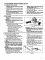
CUSTOMER RESPONSIBILITIES
A. MAINTENANCE SAFETY
1. Maintain the tool according to recom.
mended procedures. Keep the cutting line at
the proper length.
2. Disconnect the spark plug before perform-
lng maintenance except for carburetor adjust-
ments.
3. Make carburetor adjustments with the low-
er end supported to prevent the trimmer
line from contacting any object.
4. Keep others away when making carburetor
adjustments.
5. Replace trimmer head parts that are
cracked, chipped, or damaged in any other
way before using the tool.
6. Use only SF_.RS .080" diameter line. Never
use wire, rope, string, etc.
7. Use only genuine SEARS replacement
parts as recommended.
8. Inspect the entire tool. Replace damaged
parts.Check forfuelleaksand make sure allfas-
tenersareinplaceand securelyfastened.
i
B. AIR FILTER
NOTE." A dirty air filter decreases the life and per-
formance of the engine and increases fuel con-
sumption.
Do not clean the air filter in gase.
line or other flammable solvent to avoid
creating a Fa-e hazard.
1. Clean the Air Filter:
• Always after 5 tanks of fuel or 5 hours of
operation, which ever is less.
• More frequentl_ in dusty conditions.
a. Remove the two screws from the air filter
cover. Remove air filter cover. Figure 19.
b. Remove the air filter. Figure 19.
c. Wash filter in soap and water.
d. Squeeze filter dry and reinstall.
e. Reinstall the air filter cover. Install screws
and tighten securely.
i i ilill i
Air
Filter
Air FilterCover
Screws
Figure 19
_'AUTION---_.. Make sure the air filter is fitted
into the corners of the cover to keep dust
from entering the engine and causing en-
gine damage.
NOTE: If replacing the air filter, see the
Accessory List for proper part number.
i
C. DRIVE SHAFT LUBRICATION
• Lubricate the Drive Shaft:
- After each ten (10) hours of operation.
- Before operating if the tool has been
stored for 90 days or longer.
• When ordering flex shaft lube, see the
Accessory List for proper part number.
• Use the following procedure for the best re-
suits:
_. Lay drive shaft on a clean sur-
face. Avoid laying the shaft on the floor,
_avOUnd or on any. other surface that may
e dirt or debris. Even .af_ter wisping the
shaft, grease residue can pick up dirt parti-
cles that can cause damage or premature
failure.
J CAUTION; [ Take care to avoid injury your
hands and fingers with broken wires when
checking for damage or wiping the drive
shaft. A cloth will not prevent broken wires
from puncturing or tearing your skin.
1, Loosen the screwsin the throttle grip.
2. Loosen the screws in the nose cone. Slide the
tube out of the nose cone, then out of the
throttle grip.
3. Remove the drive shaft from the tube. Fig-
ure 20.
4. Check the drive shaft for broken wires, twists
or kinks, and replace if damage is found.
5. Using a clean cloth, wipe the drive shaft thor-
oughly to remove any old grease. Figure 20.
6. Apply a uniform coat of lube to the entire sur-
face of the drive shaft.
7. Inject the remaining _ontents of the container
into the top of the tube.
8. Replace drive shaft in the tube. Figure 20.
9. Reassemble tube to the throttle grip and the
nose cone. Tighten nose cone screws and
throttle grip screws securely.
T_rive Shaft
Figure 20
- 15-

D. CARBURETOR ADJUSTMENTS
YOUR SEARS PRODUCT HAS BEEN DESIGNED AND MANUFACTURED TO SPECIFICATIONS
THAT REDUCE HARMFUL EMISSIONS. After your unit has been run for 5 hours, the engine has
broken- in. To ensure that your unit is at peak performance and producing the least amoUnt of harm-
ful emissions after break-in, have your SEARS Service Center/Department adjust your carburetor
for optimum operating conditions.
Properly adjusting the carburetor is a complicated task. Read all warnings and instructions
thoroughly before starting adjustments. If you do not think that you completely understand all warn-
ings and instructions, let your SEARS Service Center/Department perform these adjustments.
A WARN a
Make carburetor adjustments with the lower
end sup]_orted to prevent the tri .n_. er line from
contacting any object. Hold tool w_th your hand;
do not use optional shoulder strap for support, i
A WARNn G
Keep others away when making carburetor ad-
ustments.
A WARNING
Serious injury to the operator and others can oc-
cur if the carburetor is not properly adjusted_
• Poor engine performance can be a result of
other causes such as dirty air filter, carbon
build-up on muffler outlets, etc. See
"Trouble Shooting Ch_ct _ before proceed-
mg with carburetor adjustments.
• For best results, it is recommended that you
have your SEARS Ser-Ace Center/Depart-
ment make all carburetor adjustments. Your
dealer has the training, experience, and tools nee-
essary to properly adjust your unit to meet our
factory performance spe_Cications. This service
is not covered by warranty. If it becomes necessary
for you to make carburetor adjustments yotLrself,
follow the described procedures very carefiflly.
• Very small adjustments can affect engine
performance. It is important to turn the screw a
very small amount per adjustment and test per-
formance before making further adjustments.
Each adjustment shouldbe no more than the
width of the slot in the adjusting screw.
• This is a complicated task and it is impor.
taut to follow instructions in sequence as
indicated.
Ie TROUBLE SHOOTING SUGGESTIONS
- Eng_me will not continue to run at idle posi-
tion, See "Idle Speed Adjustment" and "Mix-
ture Adjustment."
- Engine dies or hesitates when it should accel-
erate. See 'Tkcceleration Check."
- Loss of cutting power which cannot be cor-
rected by cleaning the air filter. See "Mixture
Adjustment."
- Engine does not return to idle from full throt-
tle within 2 seconds.See "Deceleration CheCk."
- Engine, will not run. See "Trouble Shooting
Chart. Then, ff carburetor requires adjust-
ment, begin with "Basic Carburetor Settings."
l A . J
The trimmer line will be sp'.mning during this]
procedure. Wear your protective eqmpment and |
observe all safety instructions. I
2. BASIC CARBURETOR SETrINGS
In most cases, your engine can be made to
run properly with minor carburetor adjustments.
Refer to "Trouble Shooting Suggestions, for con-
dition you are experiencing; follow instructions.
Basic carburetor settings are provided below.
• Turn the mixture screw (Figure 21 ) to the
midpoint. Do not attempt to adjust the screw
beyond the stops as damage can occur.
3. ADJUSTING PROCEDURE
a, PREPARATION
L Use fresh fuel mix (see fueling section).
2. Make sure the line extends to the length al-
lowed by the line limiter to provide correct
load on engine.
3. Start the engine. Cut grass for 3 minutes to
warm engine. The engine must be at operat-
ing temperature before carburetor adjust-
rnents can be performed correctly.
b. IDLE SPEED ADJUSTMENT
1. Allow engineto idle. Be sure the trimmer
line is extended to the maximum length al-
lowed by the line limiter.
2. Adjust idle speed screw (Figure 21 ) until
engine continues to run without staIlhag.
- Turn screw clockwise to increase engine
speed if the engine stalls or dies.
- Turn screw counterclockwise to slow en-
_in_ dowm
3. Follow instructions in '_cceleration
Check" and "Deceleration Check."
4. No fizrther adjustments are necessary if
._is satisfacto_ ..........
Mixture Screw (with Limlter Cap;
Air Filter
Cover Idle Speed Screw
Figure 21
- 16-

e. ACCELERATION CHECK
L Allow engine to idle. Be sure the trimmer
line is extended to the maximum length al-
lowed by the line limiter.
2. Squeeze trigger fully:
a.) If performance is satisfactor_ pro-
eeed to "d. Deceleration Cher_k."
b:) If the engine does not accelerate
smoothl_ turn the _ screw
counterclockwise a small mount (no
more than the width of the slot in the ad-
justing screw).
3. Repeat step"2."untilsmooth acceleration
is obtained. Do not attempt to adjust the
screw beyond the stops as damage can occur.
NOTE." It may be necessary to repeat "Idle Speed
Adjustment" through "Acceleration Check," to
obtain correct adjustments.
4. Follow the instructions in the "Decelera-
tion Check _ section.
d. DECELERATION CHECK
1. Allow engine to idle. Be sure the trimmer
line is extended to the maximum length al-
lowed by the line limiter.
2. Squeeze throttle trigger fully.
3. Allow the engine to mn at full speed for
about i second.
4. Releasethethrottletriggertotheidleposi-
tionand listentothedecelerationoftheen-
gine.Itmust retm'n toidlesmoothly and
within I to2 seconds.
a. If performance is satisfaetor_ no
further adjustments are necessary.
i i | i
b. If the eng_. e slowly or erratically
returns to idle or idles erratically,
proceed to Mixture Adjustment.
e. MIXTURE ADJUSTMENT
DO not operate engine at full
r pr?longed periods while mak-
g mLxture adjustments as damage to the
engine can occur.
I. Support the lower end so the trimmer line
is off the ground and will not make contact
with any object. Be sure the trimmer line is
extended to the maximum length allowed
by the line limiter.
2. Start the engine. Allow engine to idle, then
squeeze throttle trigger R_ly.
NOTE.. Perform steps "3." through "5." at full throt-
tle,
3. Turn mixture screw (Figure21) very
slowly clockwise until engine speed is re-
duced.
4. Turn mixture screw very slowlycounter.
clockwise.Stop when the enginebeginsto
runroughly.
5. Turn screw slowly the minimum mount
clockwise until engine runs smoothly. Do
not a_tempt to adjust the screw beyond the
stops as damage can occur.
6. Follow instructions in "Acceleration
Check" and "Deceleration Check".
[ CAUTION; IIf the engine does not operate ac-
cording to these instructions after repeat-
mg the adjusting steps, do not use the tool.
Take _t to your nearest SEARS Service Cen-
ter/Department.
H i i , H,H, HI
E. SPARK PLUG -- Replace the spark plug yearly.
H HH HI HI HH IHI, H
NOTES
-17-

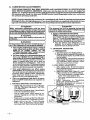
E STARTER ROPE
• Replace a starter rope that breaks. ,
i A W tNXN - i
[Do not remove the retaining tab and screw or the pul- |
| ley_ The sprlngbeneath the puHeyis trader tension and I
| can fly out and cause serious injury. If any part of the |
|pulley housing assembly is damaged other than the |
Irope, do not use tool. Take it to your nearest SEARS |
[Service Center/Department. |
L Disconnect spark plug wire. Figure 22.
2. Remove thrott]etriggerhonsingscrew_; remove throttle
trigger housing from tube.
3. Remove the barre! and ofthe throttle cable frem the trig-
ger. Figure 22 (inset),
4. Push barrel end of throttle cable into cable conduit.
Twist the barrel on cable nntil the Zfitting slips out of the
throttle plate. FigtLre 23 (inset).
5. Remove the pulleyhousingscrews (four on the front, one
by the spark plug) with the small hex wrench provided.
6. Separate the pulley housing from the engine.
7. Disconnect switch wires from switch. Figure 24.
8. Remove theropereteinerscrewfromthe screwpost. Fig-
ure 26. Remove any remaining rope.
9. Hand turn the pulley clockwise as far as it will go.
10. Turn the pulley counterclockwise until the pulley notch
is aligned with the housing notch next to the retaining
tab and screw. Figure 27.
1I. Then, turn the pulley one complete _ counterclock-
wise until the notches are aligned again.
12. Insertthe hex wrench intothe hole formed by the
notchestoholdthepulleyinposition.Figure 27 (inset-
upperleft).
13. Use a 42" lengthofreplacementrope.
14. Move away i0feet(3meters)from thefueltank withthe
replacementrope.Usea match and meltbothends ofthe
ropeto preventfraying.
15. Pullmelted ends.through a thick,cleanrag while the
rope is still-hot to obtain smooth, pointed ends.
16. Insert one end ofthe rope through the handle andsecttre
with a knot. Leave a 3/16" pigtail behind the knot. Fig-
ure 27 (inset-upper right).
I7. Insert theother end oftherope through the ropeexit hole
into the inside of the housing, into the pulley and up
through the pulley hole. Figure 27.
I8. Wrap the repe counterclockwisearound thepulley ratch-
et and tuck loose end under the rope at the pulley hole.
LeaveaIinchtaillayingflaton topofthepulleybetween
theretainerriband theretentionpoetasshown in Fig-
ures26 & 27. The ropetailmustnotextendbeyond the
raisedcircleon thepulleytopreventinterferencewith
theretainingtab.Figure27.
19. Thread theroperetainerscrewintothe screwpost.Fig-
ure 26. Do not overtightenscrew.
20, Hold rope tautatropeexitholesopulleywillnot move.
Remove hex wrench and allowrope torewind slowly.
21. Connect switch wiresto the switch. Figure 24.
22. Reassemble the puUey housing to the engine (it may be
necessary to pull on the rope to allow parts to fit together
properly). Tighten screws securely.
23. Usinga pair ofpllers, reach through the 'window' in the
air filter cover and grip the Z fitting. Figure 23. Install
the Z fitting in the hole in the throttle plate. See Fig-
ure 23 (inset). Putlonthebarrelendofthethrottlecable
to ensure that cable and throttle plate function properly.
24. Reassemble tube to the engine, Tighten screws securely.
25. Install the berrel end ofthrottle cable in the trigger. Fig-
ure 22 (inset). Re_.ssemble throttle trigger housing onto
the tube. Tighten screws securely.
26. Reconnect spark plug wire.
-18-
Spark
Screws
Wire
Throttle
Trigger Housing
hrottle
Plate
Barrel End of
Throttle Cable
-_"Nose Cone" Screws
Tube
Figure 2B Figure 24
_--- Rope
Retainer Screw
Tail
Hex Wrench
Figure 26
Rope
- Tail
Pulley
Notch
Housing
Notch
Figure 27

G. STORAGE
Immediatelyprepareyourunitforstorageattheend of
theseasonorifitwillnotbe used for30 daysor more.
WARNING:
ALLOW THE ENGINE TO COOL, AND SE-
CURE THE UNIT BEFORE STORING OR
TRANSPORTING IT IN A VEHICLE.
STORE UNIT AND FUEL IN AN AREA
WHERE FUEL VAPORS CANNOT REACH
SPARKS OR OPEN FLAMES FROM WA-
TER HEATERS, ELECTRIC MOTORS OR
SWITCHES, FURNACES, ETC.
STORE UNIT WITH ALL GUARDS IN
PLACE. POSITION SO THAT ANY SHARP
OBJECT SUCH AS BLADES CANNOT
ACClDENTLY CAUSE iNJURY TO PASS-
ER BY.
STORE THE UNIT OUT OF THE REACH
OF CHILDREN.
Followthese instructions:
1. Drain the fuel from the unit into an approved
fuelcontainer.
2. Drainthe fuellinesand carburetorby starting
theengineand lettingitrun untilitstops.
3. Allow the enginetocoolbeforestorage.
nVlPORTAN_. Itisimportanttopreventgum deposits
from forminginessentialfuelsystempartssuch asthe
carburetor,fuelfilter,fuellineor tank during storage.
Also,experienceindicatesthat alcoholblended fuels,
thosethatuseethanolormethanol (calledgasoholorox-
ygenatedfuel),can attractmoistureand form acidicgas
which willdamage your engine. To avoidengineprob-
lems,thefuelsystemshouldbe emptiedbeforestorageof
30 daysorlonger.
Fuel stabilizer is an acceptable alternative in
minimizing the formation of fuel gum deposits during
storage. Add stabilizer to the gasoline in the fuel tank or
fuel storage container. Always follow the mix instruc-
tions found on stabilizer container. Run engine at least 5
minutes after adding stabilizer to allow the stabilizer to
reach the carburetor.
GAS TRIMMER STORAGE INSTRUC-
TIONS
Ifyour trireme is to be stored for aperiod oftime, clean it
thoroughly prior to storage. Remove any dirt, saw-
dust,leaves,off,grease,etc.Storeina cleandryarea.
• Clean the entire unit.
• Clean air filter. Refer to "Customer Responsibili-
ties _.
° Open the cutting Line head assembly and clean any
dirt, grass ordebristhat has collected. Inspect the
cutting line, if old (chalky look and sticky to the
touch), remove and discard. Install fresh new line the
next time product is to be used.
• Lightly oil externa! metal surfaces to prevent rust
from forming.
CAUTION: Wear protective gloves when
handling blade. The blade Is sharp and
can cut you even when it is not moving.
• Ifyour unitisequippedwitha blade,remove itfrom
the unit.Referto%ssembly". Apply a coatingofoil
• "totheentiresurfaceofthebladeand wrap itinheavy
paper,cloth,orplastic.Alsoapplya lightcoatofoilto
gearhousingthreads,thentightenbladenut forstor-
age.
• Reassemble alllooseparts,being sure thatallhan-
dlesand guards are in placeand are securelyfas-
tened.Replaceany damaged parts.
• The recommended storagepositioniseithervertical-
ly withthe fuelcap on top,or horizontallywith the
fuel cap up. Do not store unit with the cutting
attachment up, above the engine.
Never use engine or carburetor cleaner products in the
fueltank orpermanent damage may occurtofuelsystem
components.
Craftsman 40:1 2-cycle engine oil is specially
blended with fuel stabilizers. If you do not use this
SEARS oi_ you can add a fuel stabilizer (such as Crafts-
man #33500) to your fuel tanl_
• Remove spark plug and pour I teaspoonof40:1oil
mix throughthesparkplugopening.SlowlypuI!the
starterrope8 to10timestodistributeoiltoinneren-
ginesurfaces.
• Replace spark plug with a new one of the recom-
mendedtypeandheatrange. Referto'ProductSpec-
L_Cations".
Clean airfilter.Refer to "Customer Responsibili-
ties".
€#
• Reinstall an covers and hardware removed for access;
tighten all screws and fasteners.
• Check entire _mit for loose screws, nuts, and bolts.
Replace any damaged, broken, or worn parts.
, Use fresh fuel having the proper gasollne to oil ratio
at the beginning of the next season.
OTHER
• Do not store gasoline from one season to another.
• Replace your gasoline can if your can starts to rust.
Rust and!or dirt in your fuel system wilt cause prob-
lems.
• Store your unit in a well ventilated area and covered,
if possible, to prevent dust and dirt accumulation. Do
not cover with plastic. Plastic cannot breathe and
will induce condensation and eventual rust or corro-
sion.
IMPORTANT; Never cover unit while engine and ex-
haust areas are still warm.
- 19 -

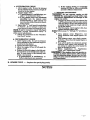
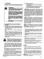
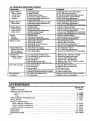
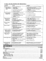
H. TROUBLE SHOOTING CHART
SYMPTOM CAUSE
Engine will not
start or will run
only for a few
seconds after
starting.
Engine will not
idle properly,
Engine wii! not
accelerate,lacks
power, or dies
under a load.
Engine
smokes
excessively.
Engine runs hot.
Cut.gilead tops
under a load or does
not turn when en-
gine is accelerated,
Line does not
advance or breaks
while cutting.
,,LJ
Line welds onto sl_ool,
LinepJl beck .............
into head.
!, Fuel tank empty,
2. Engine flooded,
3, Spark plug not firing,
4, FueI not reaching carburetor.
5. Carburetor requires adjustment.
6. None of the above.
........m..
1, Carburetor set too fast or too slow,
2. Carburetor requires adjustment.
3. None of the above.
I, Air filter
2. Spark plug fouled.
3. Carburetor requires adjustment,
4. Muffler outlets plugged.
5. None of the above.
1, Air filter dirty,
2. Fuel mixture incorrect.
3. Carburetor requires adjustment,
1, Fuel mixture incorrect.
2. Spark plug incorrect.
3. Carburetor set too low (Lean).
4, None of the above,
1, Drive S_aft not engaged,
2. Carburetor requires adjustments,
3. Drive shaft broken.
,,,,,,,,,, , ,,,.,. ,
1, Line hnproperly routed _ head.
2. Line improperly wound onto spool.
3. Line size incorrect.
4. Old cutting line,
5. Too little line outside head,
6. Dirt accumulated on cover cut-outs.
1, Line size incorrect,
2. OId cutting line.
3. Incorrect spool,
4. Crowding line against material being cut.
5. Cutting at higher speed than necessary, .........
I, Too little line outside of head.
2. Old cutting line,
REMEDY
1. Fill tank with correct fuel mixture
2. See "Starting Instructions. _
3. Install new plug/check ignition system.
4. Clean fuel filter; inspect fuel line.
5. See _Carburetor Adjustments."
6. Conta_ _our SEARS Serv:i'ceCenter/Dept.
1. See "Carburetor Adjustments."
2. See "Carburetor Adjustments."
3. Contact your SEARS Service Center!Dept.
1. Clean or replace air filter.
2. Clean or replace spark plug and re-gap.
3. See "Carburetor Adjustments. _
4. Contact your SEARS Service Center/Dept.
5. Contact your SEARS Service Center/Dept.
1. Clean or replace air filter.
2. Refuel with correct fuel mixture.
3. See "Carburetor Adjustments. _
1. See "Fueling Your Unit."
2. Replace with correct plug.
3, See "Carburetor Adjustments,"
4.Contact_rourSEAl,S ServiceCenter/Dept.
1.See "Assembly,""Tube."
2.See _CarburetorAdjustments."
3.Contactyour SEAB_ ServiceCenter/Dept.
,,,,,,,,,,,,, _ .......,
1. Remove coven Check line routing.
2, Rewind line tightly and evenly.
3. Use only ,080" diameter line.
4. Replace with new cutting line.
5. Remove coven Pull 4" of line to outside.
6. Clean cover cut-outs.
1. Use only .080" diameter line.
2. Replace with new cutting line.
3oUse proper spool.
4. Cut with tip of line.
5. Reduce cutting speeck
....1:Remove coven Puff4" °fline t°outside.
2.Replacewith new cuttingline.
IIII IIII II IIIIIIIIIIll IIIIIIIIIIIIII I I IIIIIWIH_[[ liHi IIIIIIII I
, ..Ji r • i ii. • i i illllllllllllll IrIH II I IlllllllllllIH I I
ACCESSORIES
, _ mm irl ii I i iii i iii I r HH
ITEM STOCK NO.
SAFETY GOGGLES . .... 71-85707
SEARS 2-CYCLE ENGINE OIL
--3.2 oz ............................................................................. 71-36552 .
--8 oz............................................................................... 71-36555
- - t6 oz .............................................................................. 71-36553
REPLACEMENT TRIMMER HEAD ....................................................... 71-85801
SPOOL W/_INE .......................................................................... 71-85811
NYLON CUTTING LINE
80 Ft. (.080 Dia.) Cutting Line .......................................................... 71-85773
200 Ft, (,080 Dim) Cutting Line .......................................... •.............. 71-85608
400 Ft. (.080 Dial) Cutting Line ........................................................ 71-85778
SPARK PLUG ........................................................................... 71-85854
AIR FILTER ............................................................................ 530-037331
FLEX SHAFT LUBE ..................................................................... 952-030139
- 20 -
Page is loading ...
Page is loading ...
Page is loading ...
Page is loading ...
Page is loading ...
Page is loading ...
Page is loading ...
Page is loading ...
Page is loading ...
Page is loading ...
Page is loading ...
Page is loading ...
Page is loading ...
Page is loading ...
Page is loading ...
Page is loading ...
Page is loading ...
Page is loading ...
Page is loading ...
Page is loading ...
Page is loading ...
Page is loading ...
Page is loading ...
Page is loading ...
-
 1
1
-
 2
2
-
 3
3
-
 4
4
-
 5
5
-
 6
6
-
 7
7
-
 8
8
-
 9
9
-
 10
10
-
 11
11
-
 12
12
-
 13
13
-
 14
14
-
 15
15
-
 16
16
-
 17
17
-
 18
18
-
 19
19
-
 20
20
-
 21
21
-
 22
22
-
 23
23
-
 24
24
-
 25
25
-
 26
26
-
 27
27
-
 28
28
-
 29
29
-
 30
30
-
 31
31
-
 32
32
-
 33
33
-
 34
34
-
 35
35
-
 36
36
-
 37
37
-
 38
38
-
 39
39
-
 40
40
-
 41
41
-
 42
42
-
 43
43
-
 44
44


Craftsman 358.799211 Owner's manual
- Category
- Power tools
- Type
- Owner's manual
- This manual is also suitable for
Ask a question and I''ll find the answer in the document
Finding information in a document is now easier with AI
in other languages
Related papers
-
Craftsman 358.795390 Owner's manual
-
-
-
-
-
-
-
-
-
