25
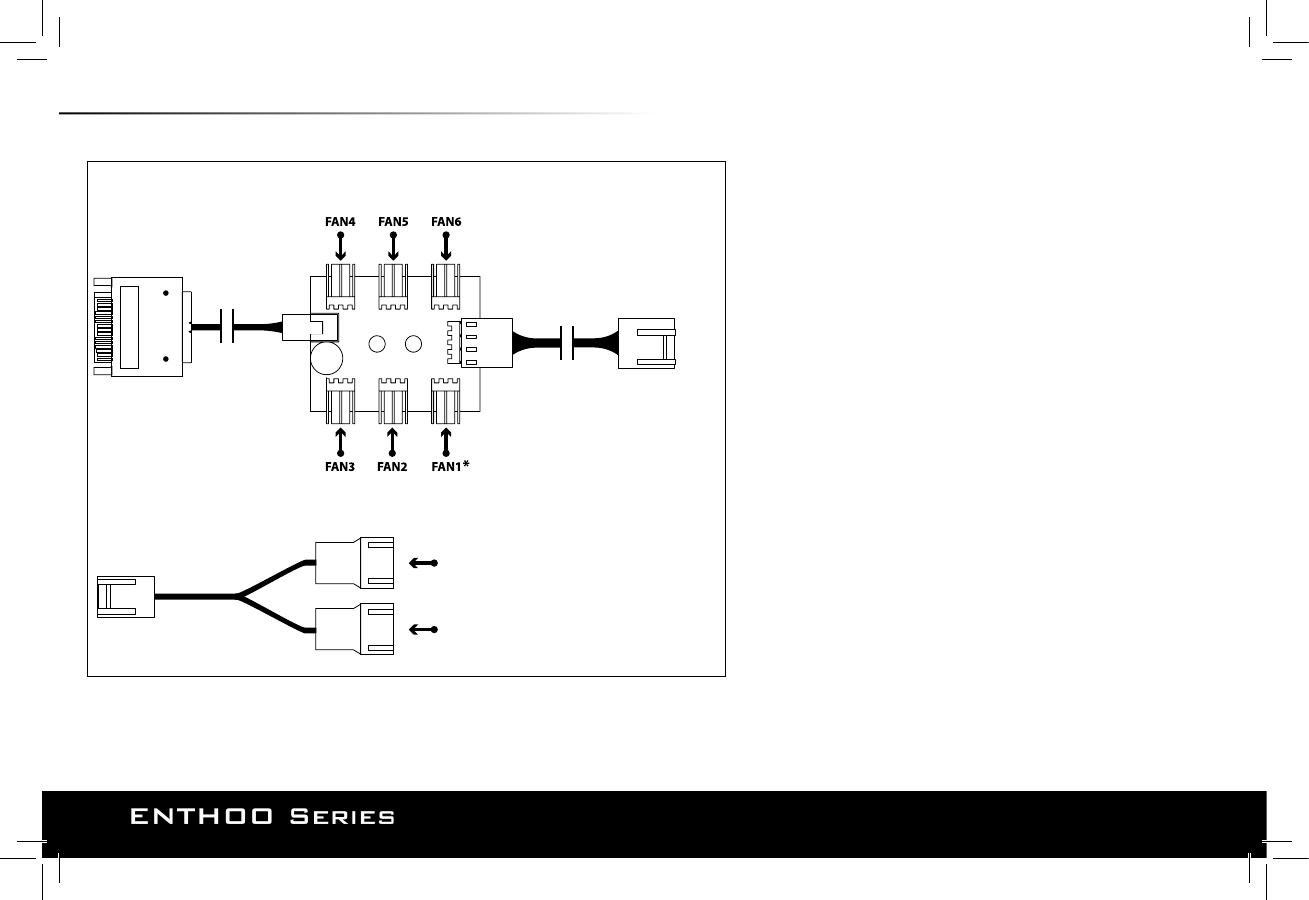
18. PWM HUB INSTALLATION
4-pin
(Motherboard CPU_Fan)
3-pin
(TO PWM HUB: FAN2, FAN3, FAN4, FAN5, FAN6)
3-pin connector
(FAN7, FAN8, FAN9, FAN10, FAN11, FAN12)
3-pin connector
(FAN7, FAN8, FAN9, FAN10, FAN11, FAN12)
SATA 12V POWER INPUT
(Power supply)
see important note
Y SPLITTER
PWM HUB
The PWM hub functions optimally when modulated by a PWM
signal from the motherboard, which will allow the greatest control
range. However, not all 4-pin motherboard connectors implement
true PWM signal modulation.
Connecting the 4-pin to CPU_FAN
For full PWM functionality, Phanteks’ PWM hub requires users to con-
nect the 4-pin connector to the “CPU_Fan” connector of the mother-
board, because all motherboard manufacturers implements a PWM
signal modulation on this connector. Connect the SATA 12V power to
power the PWM hub. Not all motherboards have their CPU_Fan
connector set on PWM signal modulation by default. Please consult
your motherboard documentation for this matter.
Connecting the 4-pin to other 4-pin header (besides the CPU_Fan)
Other 4-pin connectors can be found on modern motherboards be-
sides the “CPU_Fan” connector (e.g. “CPU_Fan2”, “CHA_Fan”, “OPT_Fan”),
however not all motherboard manufacturers implement a true PWM
signal modulation onto these connectors. These type of 4-pin connec-
tors modulate the RPM by voltage, which has a smaller control range
compared to modulation by true PWM signal.
The 12V SATA power cable can not be used to power the PWM hub if
connecting to these types of 4-pin connectors, due to the interference
with the RPM regulation by voltage (resulting in the fans running on
full RPM). The PWM hub will draw its power from the 4-pin connector,
which is limited to a total device consuming 30W in total.
Important Note:
1 motherboard connector can only read 1 RPM signal. Therefore, the motherboard
will only read the RPM signal from 1 device connected to Fan 1. The RPM form all
other devices will be regulated according to FAN 1. Y-splitter should not be connected
to FAN 1.
Please visit our website for multi-language instructions regarding PWM Hub at www.phanteks.com.
(2x included)


