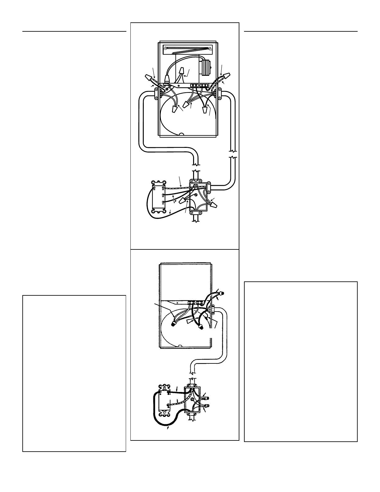
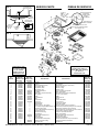
FIG. 10 MODEL 655, 659
LIGHT
LUZ
VENT
RESPI-
RADERO
WHITE
BLANCO
GRD
TIERRA
120 VAC LINE IN
LINEA DE ENTRADA DE
120VCA
BLACK
NEGRO
WHITE
BLANCO
BLACK
NEGRO
GRD
TIERRA
RED
ROJO
BLUE
AZUL
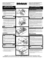
FIG. 11 MODEL 657
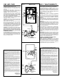
USE AND CARE
DISCONNECT ELECTRIC POWER SUPPLY BEFORE
CLEANING OR SERVICING THIS UNIT.
TO REPLACE BULB - Remove lens by gently depress-
ing sides and pull down. Use bulb rated up to 100
watts only.
TO CLEAN LENS AND GRILLE - Remove lens as
explained above. Remove bulb. Remove acorn nut
in center of reflector and lower assembly.
CAUTION: Grille and reflector are separate units.
Unplug light from white receptacle. Plastic parts can
be cleaned with mild, soapy water and dried with soft
cloth. DO NOT USE ABRASIVE CLOTHS, STEEL
WOOL PADS, OR SCOURING POWDERS.
TO CLEAN FAN ASSEMBLY - Unplug fan motor cord
from black receptacle. Remove retaining screw lo-
cated near receptacle. See FIG. 3.
CAUTION: Fan and motor will swing downward when
screw is removed. Support this unit with free hand
while removing retaining screw.
Gently vacuum fan, motor and interior of housing.
Motor is permanently lubricated - never needs oiling.
TO CLEAN HEATER ASSEMBLY - Unplug heater cord
from red receptacle. Loosen retaining screws. Place
a screwdriver tip between outer wall of housing and
heater exhaust opening. Gently pry outward until ex-
haust housing slips off support tip. See FIG. 1.
CAUTION: Unit will swing downward when released.
Support with free hand while prying with screwdriver.
Gently vacuum blower, motor and interior of housing.
Motor is permanently lubricated - never needs oiling.
METAL AND ELECTRICAL PARTS SHOULD NEVER
BE IMMERSED IN WATER.
TO REASSEMBLE ALL ABOVE PARTS - Reverse all
procedures explained above. Be sure hinge pins are
in place when reassembling fan and heater units. (See
FIG. 2.) Assemblies should not be disassembled any
further than explained above.
USO Y MANTENIMIENTO
DESCONECTE LA FUENTE DE ENERGIA ELECTRICA AN-
TES DE LIMPIAR O DAR SERVICIO A ESTA UNIDAD.
PARA REEMPLAZAR LA LAMPARA: Quite el lente,
presionando suavemente los lados y empuje. Use una
bombilla de una capacidad nominal máxima de 100 vatios.
PARA LIMPIAR EL LENTE Y LA REJILLA: saque el lente
como se explica arriba. Saque la bombilla. Saque la tuerca
ciega del centro del reflector y baje el
conjunto.
PRECAUCION: la rejilla y el reflector son unidades
separadas. Desconecte la luz del enchufe blanco. Las
piezas de plástico se pueden limpiar con agua enjabonada
y secadas con un trapo suave. NO USE TELAS ÁSPERAS,
ESPONJILLAS DE LANA DE ACERO, O POLVOS
ÁSPEROS.
PARA LIMPIAR EL CONJUNTO DEL VENTILADOR:
desconecte el cable de potencia del ventilador del enchufe
negro. Saque el tornillo de retén situado cerca del enchufe.
Vea FIG. 3.
PRECAUCION: El ventilador y el motor se vendrán un poco
hacia adelante cuando saque el tornillo. Sujete la unidad
con una mano mientras saca el tornillo de retén. Con una
aspiradora aspire suavemente el ventilador, motor e inte-
rior de la caja. El motor está permanentemente lubricado -
nunca necesita lubricación.
PARA LIMPIAR EL CONJUNTO DEL CALENTADOR:
desconecte el cable de potencia del enchufe rojo. Afloje
los tornillos de retén. Coloque la punta del destornillador
entre la pared exterior de la caja y la abertura de escape
del calentador. Haga palanca suavemente hasta que el
escape de la caja se deslice sobre la punta de soporte.
Vea FIG. 1.
PRECAUCION: El ventilador y el motor se vendrán un poco
hacia adelante cuando saque el tornillo. Sujete la unidad
con una mano mientras hace palanca con el destornillador.
Con una aspiradora aspire suavemente el ventilador, mo-
tor e interior de la caja. El motor está permanentemente
lubricado - nunca necesita lubricación.
EL METAL Y LAS PIEZAS ELECTRICAS NUNCA
DEBEN SER SUMERGIDAS EN AGUA.
PARA VOLVER A ENSAMBLAR LAS PIEZAS
MENCIONADAS ARRIBA: Efectúe los procedimientos al
revés. Asegúrese de que los pasadores de las bisagras
están en su sitio cuando vuelva a ensamblar el ventilador
y el calentador. (Vea FIG. 2). Los conjuntos no deben ser
desmontados más de lo que se explica arriba.
BROAN-NUTONE ONE YEAR LIMITED WARRANTY
Broan-NuTone warrants to the original consumer purchaser of its
products that such products will be free from defects in materials or
workmanship for a period of one year from the date of original pur-
chase. THERE ARE NO OTHER WARRANTIES, EXPRESS OR
IMPLIED, INCLUDING, BUT NOT LIMITED TO, IMPLIED WARRAN-
TIES OR MERCHANT ABILITY OR FITNESS FOR A PARTICULAR
PURPOSE.
During this one-year period, Broan-NuTone will, at its option, repair
or replace, without charge, any product or part which is found to be
defective under normal use and service.
THIS WARRANTY DOES NOT EXTEND TO FLUORESCENT LAMP
STARTERS AND TUBES. This warranty does not cover (a) normal
maintenance and service or (b) any products or parts which have
been subject to misuse, negligence, accident, improper maintenance
or repair (other than by Broan-NuTone), faulty installation or instal-
lation contrary to recommended installation instructions.
The duration of any implied warranty is limited to the one-year pe-
riod as specified for the express warranty. Some states do not allow
limitation on how long an implied warranty lasts, so the above limita-
tion may not apply to you.
BROAN-NUTONE’S OBLIGATION TO REPAIR OR REPLACE, AT
BROAN-NUTONE’S OPTION, SHALL BE THE PURCHASER’S
SOLE AND EXCLUSIVE REMEDY UNDER THIS WARRANTY.
BROAN-NUTONE SHALL NOT BE LIABLE FOR INCIDENTAL, CON-
SEQUENTIAL OR SPECIAL DAMAGES ARISING OUT OF OR IN
CONNECTION WITH PRODUCT USE OR PERFORMANCE. Some
states do not allow the exclusion or limitation of incidental or conse-
quential damages, so the above limitation or exclusion may not ap-
ply to you.
This warranty gives you specific legal rights, and you may also have
other rights, which vary from state to state. This warranty super-
sedes all prior warranties.
To qualify for warranty service, you must (a) notify Broan-NuTone at
the address stated below or telephone: 1-800-637-1453, (b) give
the model number and part identification and (c) describe the nature
of any defect in the product or part. At the time of requesting war-
ranty service, you must present evidence of the original purchase
date.
Broan-NuTone LLC
926 West State Street
Hartford, WI 53027
(1-800-637-1453)
GARANTIA BROAN-NUTONE LIMITADA POR UN AÑO
Broan-NuTone garantiza al consumidor comprador original de sus productos
que dichos productos carecerán de defectos en materiales o en mano de obra
por un período de un año a partir de la fecha original de compra. NO EXISTEN
OTRAS GARANTIAS, EXPLICITAS O IMPLICITAS, INCLUYENDO, PERO
NO LIMITADAS A, GARANTIAS IMPLICITAS DE COMERCIALIZACION O
APTITUD PARA UN PROPOSITO PARTICULAR.
Durante el período de un año, y a su propio criterio, Broan-NuTone reparará o
reemplazará, sin costo alguno cualquier producto o pieza que se encuentre
defectuosa bajo condiciones normales de servicio y uso.
ESTA GARANTIA NO SE APLICA A TUBOS Y ARRANCADORES DE
LAMPARAS
FLUORESCENTES. Esta garantía no cubre (a) mantenimiento y servicio
normales o (b) cualquier producto o piezas que hayan sido utilizadas de forma
errónea, negligente, que hayan causado un accidente, o que hayan sido
reparadas o mantenidas inapropiadamente (por otras compañías que no sean
Broan-NuTone), instalación defectuosa, o instalación contraria a las
instrucciones de instalación recomendadas.
La duración de cualquier garantía implícita se limita a un período de un año
como se especifica en la garantía expresa. Algunos estados no permiten
limitaciones en cuanto al tiempo de expiración de una garantía implícita, por lo
que la limitación antes mencionada puede no aplicarse a usted.
LA OBLIGACION DE BROAN-NUTONE DE REPARAR O REEMPLAZAR,
SIGUIENDO EL CRITERIO DE BROAN-NUTONE, DEBERA SER EL UNICO
Y EXCLUSIVO RECURSO LEGAL DEL COMPRADOR BAJO ESTA
GARANTIA. BROAN-NUTONE NO SERA RESPONSABLE POR DAÑOS
INCIDENTALES, CONSIGUIENTES, O POR DAÑOS ESPECIALES QUE
SURJAN A RAIZ DEL USO O DESEMPEÑO DEL PRODUCTO. Algunos
estados no permiten la exclusión o limitación de daños incidentales o
consiguientes, por lo que la limitación antes mencionada puede no aplicarse a
usted.
Esta garantía le proporciona derechos legales específicos, y usted puede
también tener otros derechos, los cuales varían de estado a estado. Esta
garantía reemplaza todas las garantías anteriores.
Para calificar en la garantía de servicio, usted debe (a) notificar a Broan-NuTone
al domicilio que se menciona abajo o al teléfono:1-800-637-1453, (b) dar el
número del modelo y la identificación de la pieza, y (c) describir la naturaleza
de cualquier defecto en el producto o pieza. En el momento de solicitar servicio
cubierto por la garantía, usted debe de presentar evidencia de la fecha original
de compra.
Broan-NuTone LLC
926 West State Street
Hartford, WI 53027
(1-800-637-1453)
BLACK
NEGRO
RED/ROJO
3
RED / ROJO
WHITE
BLANCO
BLACK
NEGRO
120 VAC LINE IN
LINEA DE ENTRADA DE 120 VCA
LIGHT
LUZ
VENT
RESPI-
RADERO
HEAT
CALOR
GROUND
TIERRA
RED
ROJO
BLACK
NEGRO
GROUND
TIERRA
RED
ROJO
BLUE
AZUL
WHITE
BLANCO
BLACK
NEGRO


 1
1
 2
2
 3
3
 4
4


NuTone 605RP Installation guide
Everbilt 22555 Operating instructions
Jensen 1370WHX Installation guide
NuTone QTXN110HL User manual
 Profusion Heat Ceiling-Mounted Workshop Heater Owner's manual
