BLACK DECKER BDV066 T2 Owner's manual
- Category
- Audio amplifiers
- Type
- Owner's manual
This manual is also suitable for

Owner’s Manual
Manuel de l’utilisateur
Bedienungsanleitung
Manual de Instrucciones
Gebruikershandleiding
Manuale di istruzioni
Instruktionsbok
Инструкция пользователя
RA‑1570
Stereo Integrated Amplifier
Amplificateur Stéréo Intégré
Stereo‑Vollverstärker
Amplificador Integrado Estereofónico
Geïntegreerde stereoversterker
Amplificatore integrato stereo
Integrerad stereoförstärkare
Интегрированный стерео усилитель

2 3
RA‑1570 Stereo Integrated Amplifier
2 3
RA‑1570 Stereo Integrated Amplifier
WARNING: There are no user serviceable parts inside. Refer all
servicing to qualified service personnel.
WARNING: To reduce the risk of fire or electric shock, do not expose
the unit to moisture or water. Do not expose the unit to dripping or
splashing. Do not place objects filled with liquids, such as vases, on
the unit. Do not allow foreign objects to get into the enclosure. If the
unit is exposed to moisture, or a foreign object gets into the enclosure,
immediately disconnect the power cord from the wall. Take the unit
to a qualified service person for inspection and necessary repairs.
Read all the instructions before connecting or operating the component.
Keep this manual so you can refer to these safety instructions.
Heed all warnings and safety information in these instructions and
on the product itself. Follow all operating instructions.
Clean the enclosure only with a dry cloth or a vacuum cleaner.
Do not use this unit near water.
You must allow a minimum 10 cm or 4 inches of unobstructed
clearance around the unit.
Do not place the unit on a bed, sofa, rug, or similar surface that could
block the ventilation openings. If the unit is placed in a bookcase or
cabinet, there must be ventilation of the cabinet to allow proper cooling.
Keep the component away from radiators, heat registers, stoves, or
any other appliance that produces heat.
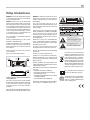
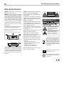
Rotel products are designed to comply with
international directives on the Restriction of
Hazardous Substances (RoHS) in electrical and
electronic equipment and the disposal of Waste
Electrical and Electronic Equipment (WEEE). The
crossed wheelie bin symbol indicates compliance and
that the products must be appropriately recycled
or processed in accordance with these directives.
This symbol means that this unit is double insulated.
An earth connection is not required.
Important Safety Instructions
WARNING:
The rear panel power cord connector is the mains
power disconnect device. The apparatus must be located in an
open area that allows access to the cord connector.
The unit must be connected to a power supply only of the type and
voltage specified on the rear panel. (USA: 120 V/60Hz, EC: 230V/50Hz)
Connect the component to the power outlet only with the supplied
power supply cable or an exact equivalent. Do not modify the
supplied cable. A polarized plug has two blades, with one wider than
the other. A grounding plug has two blades plus a third grounding
prong. These are provided for your safety. Do not defeat grounding
and/or polarization safety provisions. If the supplied plug does not
fit your outlet, please consult an electrician for replacement of the
obsolete outlet. Do not use extension cords.
The main plug of the power cordset is a disconnect device of the
apparatus. In order to completely disconnect the apparatus from the
supply mains, the main plug of the power cordset should be unplugged
from the mains (AC) outlet. The standby LED indicator will not be lit
up to show the power cord is unplugged. The disconnect device shall
remain readily operable.
Do not route the power cord where it will be crushed, pinched,
bent, exposed to heat, or damaged in any way. Pay particular
attention to the power cord at the plug and where the cord exits
the back of the unit.
The power cord should be unplugged from the wall outlet during
a lightning storm or if the unit is to be left unused for a long
period of time.
Use only accessories specified by the manufacturer.
Use only with a cart, stand, rack, bracket or shelf system
recommended by Rotel. Use caution when moving the unit in a
stand or rack to avoid injury from a tip‑over.
Use Class 2 wiring for speaker connections to ensure proper
installation and minimize the risk of electrical shock.
Immediately stop using the component and have it inspected and/
or serviced by a qualified service agency if:
• The power supply cord or plug has been damaged
• Objects have fallen or liquid has been spilled into the unit
• The unit has been exposed to rain
• The unit shows signs of improper operation
• The unit has been dropped or damaged in any way
The batteries in the remote control should not be exposed to
excessive temperature such as sunshine, fire or other heat sources.
Place the unit on a on a fixed, level surface strong
enough to support its weight. Do not place it on a
moveable cart that could tip over.

2 3
RA‑1570 Stereo Integrated Amplifier
2 3
RA‑1570 Stereo Integrated Amplifier
1
2
3
5
=
6 7 8
r t y
-
9
0
q
w
e
4
u
i
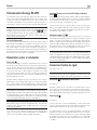
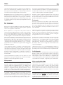
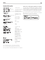
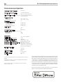
Figure 2: RR‑AX92 Remote Control
Télécommande infrarouge RR‑AX92
Fernbedienung RR‑AX92
Mando a Distancia RR‑AX92
Afstandsbediening RR‑AX92
Telecomando RR‑AX92
RR‑AX94 fjärrkontroll
Пульт ДУ RR-AX92
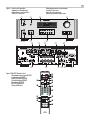
Figure 1: Controls and Connections
Commandes et Branchements
Bedienelemente und Anschlüsse
Controles y Conexiones
Bedieningselementen en aansluitingen
Controlli e connessioni
Kontroller och anslutningar
Органы управления и разъемы
RR-AX92
1 2 3
4 5 6
7 8 9
0
>10
USB PC-USB AUX 1 AUX 2
COAX1 COAX2 OPT 1 OPT 2
BYPASS
DIM
MENU
EXIT
ENT
ON
OFF
-
+
VOLUME
SPKR BSPKR A
- PRESET +
RPT
RND
PHONO TUNER CD BAL
MUTE
BASS TREBLE BAL
- TUNE +
XLR
A
B
C
D
E
F
G
H
I
J
K
L
M
N
O
Page is loading ...
Page is loading ...

6 7
RA‑1570 Stereo Integrated Amplifier
5
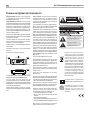
Important Notes
When making connections be sure to:
Turn off all the components in the system before hooking up any components, including loudspeakers.
Turn off all components in the system before changing any of the connections to the system.
It is also recommended that you:
Turn the volume control of the amplifi er all the way down before the amplifi er is turned on or off.
Remarques importantes
Pendant les branchements, assurez-vous que :
Tous les maillons sont éteints avant leur branchement, quels qu’ils soient, y compris les enceintes acoustiques.
Éteignez tous les maillons avant de modifi er quoi que ce soit au niveau de leurs branchements, quels qu’ils soient.
Il est également recommandé de :
Toujours baissez le niveau sonore via le contrôle de volume, avant d’allumer ou d’éteindre l’amplifi cateur.
Wichtige Hinweise
Achten Sie beim Herstellen der Verbindungen auf Folgendes:
Schalten Sie alle Komponenten im System ab, bevor Sie Geräte (einschließlich Lautsprecher) anschließen.
Schalten Sie alle Komponenten im System ab, bevor Sie Anschlüsse im System verändern.
Ferner empfehlen wir, dass
Sie die Lautstärke herunterdrehen, bevor Sie die Endstufe ein- oder abschalten.
Notas Importantes
Cuando realice las conexiones, asegúrese de que:
Desactiva todos los componentes del equipo, cajas acústicas incluidas, antes de conectar cualquier nuevo componente en el mismo.
Desactiva todos los componentes del equipo antes de cambiar cualquier conexión del mismo.
También le recomendamos que:
Reduzca el nivel de volumen de su amplifi cador a cero antes de activarlo o desactivarlo.
Héél belangrijk:
Bij het maken van de verbindingen:
Zorg dat niet alleen de RA-1570, maar de gehele installatie uitstaat, als nog niet alle verbindingen gemaakt zijn.
Zorg dat niet alleen de RA-1570, maar de gehele installatie ook uitstaat, als u verbindingen gaat wijzigen.
Wij raden u ook aan om
de volumeregelaar van de voorversterker geheel dicht te draaien (volkomen naar links) wanneer u uw eindversterker aan- of uitzet.
Note importanti
Quando effettuate i collegamenti assicuratevi di:
Spegnere tutti i componenti del sistema prima di collegare qualsiasi componente, inclusi i diffusori.
Spegnere tutti i componenti del sistema prima di modifi care qualsiasi connessione nel sistema.
Vi raccomandiamo inoltre di:
Portare il volume a zero prima di accendere o spegnere l’amplifi catore.
Viktigt
Tänk på följande när du gör anslutningar:
Stäng av alla komponenter i anläggningen innan du ansluter nya komponenter, inklusive högtalare.
Stäng av alla komponenter i anläggningen innan du ändrar någon anslutning i anläggningen.
Vi rekommenderar också att du
Vrider ner volymen på förstärkaren helt och hållet innan förstärkaren stängs av eller sätts på.
è‰ ÔÓ‰ÒÓ‰ËÌÂÌËÂÏ:
Ç˚Íβ˜ËÚ ‚Ò ÍÓÏÔÓÌÂÌÚ˚, ‚Íβ˜‡fl ÍÓÎÓÌÍË.
Ç˚Íβ˜ËÚ ‚Ò ÍÓÏÔÓÌÂÌÚ˚ ‚ ‚‡¯ÂÈ ÒËÒÚÂÏÂ, ÔÂʉ ˜ÂÏ ˜ÚÓ-ÚÓ ‚ ÌÂÈ ÏÂÌflÚ¸.
êÂÍÓÏẨÛÂÚÒfl Ú‡ÍÊÂ:
Ç˚‚ÂÒÚË „ÓÏÍÓÒÚ¸ ÛÒËÎËÚÂÎfl ̇ ÏËÌËÏÛÏ, Ô‰ ÚÂÏ Í‡Í ‚Íβ˜‡Ú¸ ËÎË ‚˚Íβ˜‡Ú¸ „Ó.

6 7
RA‑1570 Stereo Integrated Amplifier
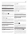
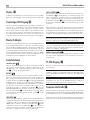
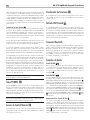
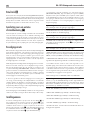
About Rotel
Our story began over 50 years ago. Over the decades, we have received
hundreds of awards for our products and satisfied hundreds of thousands
of people who take their entertainment seriously - like you!
Rotel was founded by a family whose passionate interest in music led
them to manufacture high-fidelity components of uncompromising quality.
Through the years, that passion has remained undiminished and the family
goal of providing exceptional value for audiophiles and music lovers,
regardless of their budget, is shared by all Rotel employees.
Rotel’s engineers work as a close team, listening to, and fine tuning, each
new product until it reaches their exacting musical standards. They are
free to choose components from around the world in order to make that
product the best they can. You are likely to find capacitors from the United
Kingdom and Germany, semiconductors from Japan or the United States,
while toroidal power transformers are manufactured in Rotel’s own factory.
We all have concerns about our environment. And, as more and more
electronics are produced and later discarded, it is especially important for
a manufacturer to do all it can to engineer products that have a minimum
negative impact on landfill sites and water tables.
At Rotel, we are proud to do our part. We have reduced the lead content
in our electronics by using special ROHS solder, while our new Class D
(not digital) amplifiers are up to five times more efficient than our legacy
designs and still deliver power and performance. These products run
cool, give minimum wasted energy, are good for the environment and
give better sound too.
Finally, we have printed this manual on recycled paper stock.
While we understand that these are small first steps, they are still important
ones. And we continue to pursue new methods and materials for a cleaner
and greener manufacturing process. All of us at Rotel thank you for buying
this product. We are sure it will bring you many years of enjoyment.
A Word About Watts
This amplifier’s power output is quoted as 120 watts for each channel,
when both channels are operating together at full power. Rotel has chosen
to specify the power output in this way because, in Rotel’s experience,
it gives the truest value of the receiver or amplifier’s power capability.
When comparing specifications for different products, you should be
aware that power output is often specified in other ways, so you may
not be comparing like with like. For example, the power output may be
quoted with only one channel operating, giving a higher maximum figure.
A loudspeaker’s impedance rating indicates the electrical resistance or
load it offers when connected to the amplifier, usually 8 ohms or 4 ohms.
The lower the impedance, the more power the speaker will need. In effect,
a 4 ohm speaker will require twice as much power as an 8 ohm speaker.
However, Rotel amplifiers are designed to work into any speaker
impedance between 8 and 4 ohms, and with all the channels working
up to their full power. Because Rotel designs are optimized for use with
all channels operating together, Rotel is able to specify the true power
output for both channels.
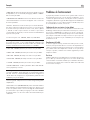
Contents
Important Safety Instructions .......................................2
Figure 1: Controls and Connections 3
Figure 2: RR‑AX92 Remote Control 3
Figure 3: Analog Inputs and Speaker Output Connections 4
Figure 4: Balanced (XLR) Inputs 5
Figure 5: Digital Input and 12 Volt Trigger out Connections 5
Important notes 6
About Rotel .................................................... 7
A Word About Watts .............................................7
Getting Started ................................................. 8
A Few Precautions 8
Placement 8
Cables 8
The RR‑AX92 Remote Control ......................................8
Remote Control Batteries 8
AC Power and Control ............................................8
AC Power Input
i
8
Power Switch and Power Indicator
1
9
12V Trigger Connection
u
9
Input Signal Connections .......................................... 9
Phono Input
0
and Ground Connection 9
Line Level Inputs
0
9
Balanced (XLR) Inputs
= 9
Digital Signal Inputs
q
...........................................9
Preamp Outputs
-
.............................................9
Preamp / Power Amp Jumpers
ey
................................9
Speaker Outputs
r
............................................10
Speaker Selection 10
Speaker Wire Selection 10
Polarity and Phasing 10
Speaker Connection
r
10
Phones Output
5
.....................................
10
Remote Sensor
2
..........................................10
Display
3
................................................10
Front USB Input
6
..........................................10
Bluetooth Connection
.........................................10
Audio Controls .................................................10
VOLUME Control
4
B
10
Balance Control
9
C
10
Tone Control Bypass K 11
BASS and TREBLE Tone Controls
9
C
11
Function Control
8
J
11
PC‑USB Input
q
............................................11
Computer I/O Connector
w
...................................11
Rotel Link
t
..............................................11
EXT REM IN Jack
u
.........................................11
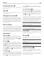
Protection Circuit ...............................................11
Settings Menu .................................................11
Troubleshooting ................................................12
Power Indicator Is Not Illuminated 12
Fuse replacement 12
No Sound 12
Specifications ..................................................13

8 9
RA‑1570 Stereo Integrated Amplifier
Getting Started
Thank you for purchasing the Rotel RA-1570 Stereo Integrated Amplifier.
When used in a high-quality music audio system, it will provide years
of musical enjoyment.
The RA-1570 is a full featured, high performance component. All aspects
of the design have been optimized to retain the full dynamic range and
subtle nuances of your music. The RA-1570 has a highly regulated power
supply incorporating a Rotel custom-designed toroidal power transformer
and custom-made slit foil capacitors. This low impedance power supply has
ample power reserves, which enables the RA-1570 to easily reproduce
the most demanding audio signals. This type of design is more expensive
to manufacture, but it is better for the music.
The printed circuit boards (PCB) are designed with Symmetrical Circuit
Traces. This insures that the precise timing of the music is maintained
and faithfully recreated. The RA-1570 circuitry uses metal film resistors
and polystyrene or polypropylene capacitors in important signal paths.
All aspects of this design have been examined to ensure the most faithful
music reproduction.
The main functions of the RA-1570 are easy to install and use. If you
have experience with other stereo systems, you shouldn’t find anything
perplexing. Simply plug in the associated components and enjoy.
A Few Precautions
WARNING: To avoid potential damage to your system, turn off ALL
the components in the system when connecting or disconnecting the
loudsp-eakers or any associated components. Do not turn the system
components back on until you are sure all the connections are correct
and secure. Pay particular attention to the speaker wires. There must
be no loose strands that could contact the other speaker wires, or
the chassis of the amplifier.
Please read this manual carefully. In addition to basic installation and
operating instructions, it provides valuable information on various RA-1570
system configurations as well as general information that will help you get
optimum performance from your system. Please contact your authorized
Rotel dealer for answers to any questions you might have. In addition,
all of us at Rotel welcome your questions and comments.
Save the RA-1570 shipping carton and all enclosed packing material for
future use. Shipping or moving the RA-1570 in anything other than the
original packing material may result in severe damage to your amplifier.
Fill out and send in the owner’s registration card packed with the RA-1570.
Also be sure to keep the original sales receipt. It is your best record of
the date of purchase, which you will need in the event warranty service
is ever required.
Placement
Like all audio components that handle low-level signals, the RA-1570
can be affected by its environment. Avoid placing the RA-1570 on top
of other components. Also avoid routing audio signal cables near power
cords. This will minimize the chance it will pick up hum or interference.
The RA-1570 generates heat as part of its normal operation. The heat
sinks and ventilation openings in the amplifier are designed to dissipate
this heat. The ventilation slots in the top cover must be open. There should
be 10 cm (4 inches) of clearance around the chassis, and reasonable
airflow through the installation location, to prevent the amplifier from
overheating.
Remember the weight of the amplifier when you select an installation
location. Make sure that the shelf or cabinet can support it. We recommend
installing the RA-1570 in furniture designed to house audio components.
Such furniture is designed to reduce or suppress vibration which can
adversely affect sound quality. Ask your authorized Rotel dealer for advice
about component furniture and proper installation of audio components.
The RA-1570 is supplied with an RR-AX92 remote control and must be
placed where the infrared signal from the remote can reach the front
panel Remote Sensor.
Cables
Be sure to keep the power cords, digital signal cables and regular
audio signal cables in your installation away from each other. This will
minimize the chance of the regular audio signal cables picking up noise
or interference from the power cords or digital cables. Using only high
quality, shielded cables will also help to prevent noise or interference from
degrading the sound quality of your system. If you have any questions
see your authorized Rotel dealer for advice about the best cable to use
with your system.
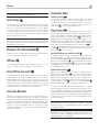
The RR‑AX92 Remote Control
Some functions can be done with either the front panel controls, or the
supplied RR-AX92 remote control. When these operations are described,
the square call out numbers refer to the main unit, while the encircled
letters refer to the remote control.
NOTE: The remote control can be used to operate the basic functions
of Rotel tuners and CD players. Remote control keys labeled
GHMN
can be used to operate CD or Tuner functions in your system. For the
remote to operate properly, make sure both the remote and the CD
or Tuner are both in same remote code.
Remote Control Batteries
Two UM-4/AAA size batteries (supplied) must be installed before the
remote control can be used. To install the batteries, remove the cover on
the back of the RR-AX92. Install the batteries as shown in the illustration
in the battery well. Test the control for proper operation, then replace
the cover. When the batteries become weak the remote control won’t
operate the RA-1570 consistently. Installing fresh batteries should eliminate
the problem.
AC Power and Control
AC Power Input
i
Because of its relatively high power rating, the RA-1570 can draw
considerable current. Therefore, it should be plugged directly into a
2-pin polarized wall outlet. Do not use an extension cord. A heavy duty
multi-tap power outlet strip may be used if it (and the wall outlet) is
rated to handle the current demanded by the RA-1570 and all the other
components connected to it.
Your RA-1570 is configured at the factory for the proper AC line voltage
in the country where you purchased it (either 120 volts AC or 230

8 9
RA‑1570 Stereo Integrated Amplifier
volts AC with a line frequency of either 50 Hz or 60 Hz). The AC line
configuration is noted on a decal on the back panel.
NOTE: Should you move your RA-1570 to another country, it is
possible to reconfigure your amplifier for use on a different line
voltage. Do not attempt to perform this conversion yourself. Opening
the enclosure of the RA-1570 exposes you to dangerous voltages.
Consult a qualified service person or the Rotel factory service
department for information.
NOTE: Some products are intended for sale in more than one country
and as such are supplied with more than one AC cord. Please only
use the one appropriate for your country/region.
If you are going to be away from home for an extended period of time
such as a month long vacation, it is a sensible precaution to unplug
your amplifier (as well as other audio and video components) while
you are away.
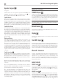
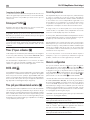
POWER Switch and Power Indicator
1
Press the front panel Power Switch button, to turn the unit on. The Power
Indicator light is illuminated when the unit is on. Press Power Switch
button again to turn the unit off.
When the power switch is in the ON position, the remote control ON
and OFF buttons may be used to activate the RA-1570. In Standby mode
the power LED remains lit, but the display is turned OFF.
12V TRIGGER Connection
u
Some audio components can be turned on automatically when they receive
a 12V turn on “signal”. The two12V Trigger Outputs of the RA-1570
provide the required signal. Connect compatible components to the RA-
1570 with a conventional 3.5mm mini plug cable. When the RA-1570
is in turn off mode, the trigger signal is interrupted, so the components
controlled by it are turned off.
NOTE: If you are using other units in the series with Rotel link, please
use the Rotel Link connection to turn the units on or off. Do not connect
both the Rotel Link and 12V trigger cables. The 12V trigger’s power
on or off features will override the Rotel Link features.
Input Signal Connections
See Figure 3,4,5
NOTE: To prevent loud noises that neither you nor your speakers
will appreciate, make sure the system is turned off when you make
any signal connections.
Phono Input
0
and Ground Connection (GND)
See Figure 3
Plug the cable from the turntable into the appropriate left and right phono
inputs. If the turntable has a “ground” wire, connect it to the screw terminal
to the left of the Phono inputs. It will help prevent hum and noise.
Line Level Inputs
0
See Figure 3
The CD, Tuner, and Aux inputs of the amplifier are analog “line level”
inputs. These inputs are for connecting components such as CD players
or other audio playback devices with an analog audio output.
The left and right channels are clearly labeled and should be connected to
the corresponding channels of the source component. The Left connectors
are white, the Right connectors are red. Use high quality RCA cables for
connecting input source components to the RA-1570. Ask your authorized
Rotel dealer for advice about cables.
Balanced (XLR) Inputs
=
See Figure 4
A pair of balanced XLR inputs accept audio signals from CD player, Blu-
ray player or other source components with XLR outputs.
NOTE: You should choose only one method of ananlog connection
from a source component to RA-1570. Do not connect both the
RCA and XLR outputs of a source component to the RA-1570 at the
same time.
Digital Signal Inputs
q
See Figure 5.
There are two sets of digital inputs labeled COAX 1 and 2, OPT 1
and 2. Connect the COAXIAL or OPTICAL PCM outputs of your source
component into these sockets. The digital signals will be decoded and
played by the amplifier. The unit is capable of decoding PCM signals
up to 24 bit, 192kHZ.
Preamp Outputs
-
The amplifier has a set of preamp outputs labeled PREOUT 1. The signal
from the source selected with the Function Selector is always available
from these outputs. Typically the PREOUT 1 output is used to provide a
signal to another integrated amplifier or power amplifier, which is used
to drive remote speakers.
NOTE: Changes to the settings of the Volume, Balance or Tone
controls affect the signal from the Preamp Outputs.
Preamp / Power Amp Jumpers
ey
These connectors, labeled ”Pre Out 2” and “Main In”, are normally
connected by a set of solid metal jumper connectors. They provide a
convenient insertion point for virtually any type of signal processor. To
use these connectors, pull out the jumper connectors. Using high quality
cables, connect the “Pre Out 2” connectors to the inputs of the signal
processor. Connect the outputs of the signal processor to the “Main In”
connectors.

10 11
RA‑1570 Stereo Integrated Amplifier
Speaker Outputs
r
See Figure 3
The RA-1570 has two sets of speaker outputs, labeled SPEAKER A and
SPEAKER B. The speaker outputs are controlled by the switch
7
on
the front panel and the buttons O on the remote control.
Speaker Selection
If only one set of speakers will be used at any given time, the speakers
may have an impedance as low as 4 ohms. If there are times when
both the A and B speakers will be used, all the speakers should have an
impedance of 8 ohms or more. Speaker impedance ratings are less than
precise. In practice, very few loudspeakers will present any problems for
the RA-1570. See your authorized Rotel dealer if you have any questions.
Speaker Wire Selection
Use insulated two-conductor stranded wire to connect the RA-1570 to
the speakers. The size and quality of the wire can have an audible effect
on the performance of the system. Standard speaker wire will work, but
can result in lower output or diminished bass response, particularly over
longer distances. In general, heavier wire will improve the sound. For
best performance, you may want to consider special high-quality speaker
cables.Your authorized Rotel dealer can help in the selection of cables
for your system.
Polarity and Phasing
The polarity – the positive/negative orientation of the connections – for
every speaker and amplifier connection must be consistent so all the
speakers will be in phase. If the polarity of one connection is reversed,
bass output will be very weak and stereo imaging degraded. All wire
is marked so you can identify the two conductors. There may be ribs
or a stripe on the insulation of one conductor. The wire may have clear
insulation with different color conductors (copper and silver). There may
be polarity indications printed on the insulation. Identify the positive and
negative conductors and be consistent with every speaker and amplifier
connection.
Speaker Connections
r
Turn off all the components in the system before connecting the speakers.
The RA-1570 has color-coded binding post type speaker connectors on
the back panel. These connectors accept bare wire, connector lugs, or
dual banana type connectors. (except in European Community countries
where their use is not permitted)
Route the wire from the RA-1570 to the speakers. Give yourself enough
slack so you can move the components to allow access to the speaker
connectors.
If you are using dual banana plugs, connect them to the wires and then
plug into the backs of the binding posts. The thumbscrews of the binding
posts should be screwed in all the way (clockwise).
If you are using terminal lugs, connect them to the wires. If you are
attaching bare wires directly to the binding posts, separate the wire
conductors and strip the insulation from the end of each conductor. Be
careful not to cut into the wire strands. Unscrew (turn counterclockwise)
the binding post. Place the connector lug or wire around the binding
post shaft. Turn the binding post clockwise to clamp the connector lug
or wire firmly in place.
NOTE: Be sure there are no loose wire strands that could touch
adjacent wires or connectors.
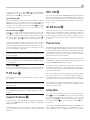
PHONES Output
5
The Phones output allows you to connect headphones for private listening.
This output accommodates standard stereo phone (1/8”) plugs. Plugging
in a set of headphones does not cut off the signal to the speakers. Use
the Speaker Selector to turn off the speakers. The settings of the Function
Selector determines which source is heard.
NOTE: Because the sensitivity of speakers and headphones can
vary widely, always reduce the volume level before connecting or
disconnecting headphones.
Remote Sensor
2
This remote sensor window receives IR commands from the remote control.
Please do not block this sensor.
Display
3
The front panel display shows the source selected, volume level and
tone settings.
Front USB Input
6
The front USB input can be connected to a iPod, iPhone, MP3 players or a
Bluetooth dongle (supplied) for wireless streaming. With iPod or iPhones,
simply plug the device into the front USB and select USB function from
the source selector. The iPod, iPhone remains active. Search and play
tracks as usual and the music will be played through the Rotel system.
Bluetooth Connection
Insert the supplied Bluetooth Dongle into the front USB for wireless
streaming via Bluetooth, from your device (i.e. mobile phones) to the
amplifier. From your mobile device, look for “Rotel Bluetooth” and
connect to it. Connection is normally automatic, but if prompted for a
password, please press “0000” then press ENT (if necessary) on the
remote and your device.
Audio Controls
VOLUME Control
4
B
Turn the controls clockwise to increase the volume, or counter clockwise
to decrease the volume. From the remote control press the volume + or -
key to turn the volume up or down. Press the MUTE B key to completely
mute the volume.
BALANCE Control
9
C
The Balance Control adjusts the left-to-right balance of the sound output.
The factory default is the center position or “0”. To change the balance
from the front panel, press the MENU
9
key to toggle the front display
to BALANCE SETTING mode. Then press the - or + keys on the front panel
to change the value to LEFT or RIGHT. The value can change from L15

10 11
RA‑1570 Stereo Integrated Amplifier
to R15. From the remote, press the BAL C key to access the BALANCE
SETTING menu, then press the LEFT or RIGHT E key to adjust. When
finished, press the EXIT F key to exit the menu.
Tone Control Bypass K
Bass and Treble Control (Tone Control) circuits are bypassed at factory
default to ensure the purest possible sound. The front display will show
TONE BYPASS. To turn on the tone control, press the BYPASS K key on
the remote control. From the front panel press the MENU
9
key to toggle
to the Bypass control then press the + or – keys to turn bypass on or off.
Bass and Treble Controls 9C
Set the Bass or Treble controls from the front panel by pressing the
MENU9 key to toggle to either the Bass or Treble Setting menu. Then
press the - or + key to adjust the value. The Bass and Treble values range
from -10 to +10. From the remote control, press the Bass or Treble key C,
then press the LEFT or RIGHT E keys on the remote to adjust the value.
A properly setup high-performance audio system produces the most
natural sound with little or no adjustment of the tone controls. Use these
controls sparingly. Be particularly careful when turning the controls up
as this increases the power output in the bass or treble range, increasing
the load on the amplifier and speakers.
NOTE: Setting the Bass and Treble controls do not automatically turn
on the tone control. To turn on tone control, refer to previous section
Tone Control Bypass.
NOTE: Tone Bypass, Bass, Treble and Balance settings are temporary
and not saved after power off. To make permeant changes please
see Settings Menu.
Function Control
8
J
The Function control selects the input signal source. From the front panel or
remote press the corresponding input key to select the source to listen to.
PC‑USB Input q
Connect this input using the supplied USB cable to the USB socket of
your computer.
NOTE: You will need to install the USB driver located on the CD supplied
with the RA-1570 onto your computer to allow it to send audio to the
RA-1570 via USB.
NOTE: Upon successful installation of the driver, you may need to
select the ROTEL audio driver from the audio/speaker setup of your
computer.
Computer I/O Connector w
The RA-1570 can be controlled via RS232 for integration with automation
systems. The COMPUTER I/O input accepts a standard straight DB-9
Male-to-Female cable.
For additional information on the connections, software, and operating
codes for computer control of the RA-1570, contact your authorized
Rotel dealer.
ROTEL LINK
t
This 3.5 mm stereo mini-jack (labeled ROTEL LINK IN) can optionally attach
to Rotel network enabled products with ROTEL LINK OUT connections.
This allows the attached Rotel products to communicate with each other
and be controlled via the Rotel Remote App (available for download on
the iTunes
®
store).
EXT REM IN Jack
u
This 3.5mm mini-jack receives command codes from industry-standard
infrared receivers via hard-wired connections. This feature could prove
useful when the unit is installed in a cabinet and the front-panel sensor is
blocked. Consult your authorized Rotel dealer for information on these
external repeaters and the proper wiring of a jack to fit the mini-jack
receptacle.
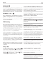
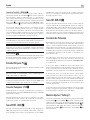
Protection Circuit
The amplifier has both thermal and over-current protection circuitry that
protects the amplifier against damage in the event of extreme or faulty
operating conditions. The protection circuits are independent of the audio
signal and have no impact on sonic performance. Instead, the protection
circuits monitor the temperature of the output devices and shut down the
amplifier if temperatures exceed safe limits.
Most likely, you will never see this protection circuitry in action. However,
should a faulty condition arise, the amplifier will stop playing and will
display “AMP PROTECTION“ on the front panel
If this happens, turn the amplifier off. Let it cool down for several minutes,
and attempt to identify and correct the problem that caused the protection
circuitry to engage. When you turn the amplifier back on, the protection
circuit will automatically reset.
In most cases, the protection circuitry activates because of a fault condition
such as shorted speaker wires, or inadequate ventilation leading to an
overheating condition. In very rare cases, highly reactive or extremely low
impedance speaker loads could cause the protection circuit to engage.
If the protection circuitry triggers repeatedly and you are unable to isolate
and correct the faulty condition, contact your authorized Rotel dealer for
assistance in troubleshooting.
Settings Menu
You can access the settings menu from the front panel by pressing the
MENU
9
button or the MENU D button on the remote. You can change
the value of the selected option by pressing the +/- key on the front
panel or LEFT/RIGHT E key on the remote. Step through the sub-menus
by pressing the MENU
9
key on the front panel or MENU D button
on the remote.
• Tone Control: TONE BYPASS ON/OFF, BASS level and TREBLE levels
can be changed to desired settings. Press the ENTER key on the front
panel or ENT on the remote to toggle between the tone setup options.

12 13
RA‑1570 Stereo Integrated Amplifier
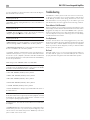
Troubleshooting
Most difficulties in audio systems are the result of incorrect connections,
or improper control settings. If you encounter problems, isolate the area
of the difficulty, check the control settings, determine the cause of the
fault and make the necessary changes. If you are unable to get sound
from the RA‑1570, refer to the suggestions for the following conditions:
Power Indicator Is Not Illuminated
The Power Indicator ring around the power button and the basic items
in the Display window should be illuminated whenever the RA-1570 is
plugged into the wall power outlet and the POWER switch is pushed in.
If it does not light, test the power outlet with another electrical device,
such as a lamp. Be sure the power outlet being used is not controlled by
a switch that has been turned off.
Fuse Replacement
If another electrical device works when plugged into the power outlet,
but the Power Indicator still will not light when the RA-1570 is plugged
into the wall outlet, it indicates that the internal power fuse may have
blown. If you believe this has happened, contact your authorized Rotel
dealer to get the fuse replaced.
No Sound
Check the signal source to see if it is functioning properly. Make sure
the cables from the signal source to the RA-1570 inputs are connected
properly. Check the wiring between the RA-1570 and the speakers.
(For more information on Tone Control refer to the Tone Control Bypass,
Bass and Treble control sections)
NOTE: These settings are stored permanently even after the RA-
1570 is powered off.
• BALANCE: Change left/right balance (For more information on
Balance sections)
NOTE: These settings are stored permanently even after the RA-
1570 is powered off.
• DIMMER: Dims the display in 7 steps. This can also be temporary
changed using the DIM L button on the remote control.
NOTE: These settings are stored permanently even after the RA-
1570 is powered off.
• ROTEL LINK RCD, selects how the CD player is connected to the amplier,
either CD (analog), COAX1 or COAX2. CD is the factory default.
• POWER ON MAX VOLUME: This sets the maximum volume level when
the unit is turned ON. “45” is the factory default.
• Fixed Gain: Congures a Fixed Volume level for a specied input. To
enable this feature press the +/- keys to select the desired fixed volume
level for Aux 1, Coax 1, Optical 1, PC-USB or USB. When enabled and
the input with a Fixed Volume is selected, the Volume level will immediately
be set to the specified level.
Valid settings include: VARIABLE, FIXED 1‑95, FIXED MAX.
NOTE: The Volume knob on the front panel and Volume +/- keys
on the IR remote are disabled when the volume is Fixed. To disable
this feature set the Fixed Volume level to “Variable”.
• AUX1 VOL: VARIABLE (disabled) is factory default.
• COAX1 VOL: VARIABLE (disabled) is factory default.
• OPT1 VOL: VARIABLE (disabled) is factory default.
• PC‑USB VOL: VARIABLE (disabled) is factory default.
• USB VOL: VARIABLE (disabled) is factory default.
• PC‑USB AUDIO CLASS: Change supported PC‑USB Audio Class of
the attached device.
NOTE: Some computers attached to the PC-USB do not support USB
Audio Class 2.0 and do not support 24/192 audio playback. If needed
the PC-USB can be configured for USB Audio Class 1.0. Please consult
your computer operating system for details.
• Software Version : This shows the current software version loaded into
the amplifier.
• FACTORY DEFAULT: This sets the unit back to the original state as when
it left the factory. Press the + key on the front panel or Right key on the
remote control to select <YES> then press the “ENTER” key on the front
panel or “ENT” on the remote control.

12 13
RA‑1570 Stereo Integrated Amplifier
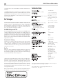
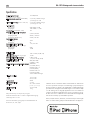
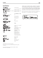
Specifications
Continuous Power Output 120 watts/channel
(20-20 kHz, < 0.03%, 8 ohms)
Total Harmonic Distortion (20Hz-20kHz) < 0.03% at rated power,
1/2 power, or 1 watt
Intermodulation Distortion (60 Hz : 7 kHz, 4:1) < 0.03% at rated power,
1/2 power or 1 watt
Frequency Response:
Phono Input 20Hz-20kHz, ±0.5dB
Line Level Inputs 10Hz-100kHz, +1, –3dB
Damping Factor (20Hz-20kHz, 8 ohms) 180
Input Sensitivity / Impedance
Phono Input (MM) 2.25mV / 68k ohms
Line Level Inputs (RCA) 285mV / 100k ohms
Line Level Inputs (Balanced) 570mV / 50k ohms
Input Overload
Phono Input 30mV
Line Level Inputs 4V
Preamplifier Output / Impedance 1.5V / 470 ohms
Signal to Noise Ratio (IHF “A” weighted)
Phono Input 80dB
Line Level Inputs 100dB
Digital Section
Frequency Response 10Hz - 95kHz (±3.0dB, Max)
Signal to Noise Ratio (IHF ”A” weighted) 100 dB
Input Sensitivity/Impedance 0 dBfs / 75 ohms
Preout Level/Impedance 1.2 V/ 470 ohms (at -20 dB)
USB/iPod Digital Signals WAV, MP3, WMA
(up to 48kHz 16 bit)
Coaxial/Optical Digital Signals SPDIF LPCM
(up to 192kHz 24 bit)
PC-USB USB Audio Class 1.0
(up to 24 bit/96kHz)
USB Audio Class 2.0
(up to 24 bit/192kHz)*
*Driver installation required
Power Requirements:
USA: 120 Volts, 60 Hz
EC: 230 Volts, 50 Hz
Power Consumption 400 watts
Standby Power Consumption < 0.5 watts
Dimensions (W x H x D) 431 x 144 x 350 mm
(17 x 5
7
/
8
x 13
3
/
4
ins)
Front Panel Height 3U (132.6mm, 5
1
/
4
ins)
Weight (net) 13kg, 28.7 lbs.
All specifications are accurate at the time of printing.
Rotel reserves the right to make improvements without notice.
Rotel and the Rotel Hi-Fi logo are registered trademarks of The Rotel Co, Ltd.,
Tokyo, Japan.
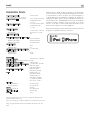
“Made for iPod,” and “Made for iPhone,” means that an electronic
accessory has been designed to connect specifically to iPod or iPhone,
respectively, and has been certified by the developer to meet Apple
performance standards. Apple is not responsible for the operation of
this device or its compliance with safety and regulatory standards.
Please note that the use of this accessory with iPod, or iPhone may affect
wireless performance.
iPhone, iPod, iPod classic, iPod nano, and iPod touch are trademarks of
Apple Inc., registered in the U.S. and other countries.
Page is loading ...
Page is loading ...
Page is loading ...
Page is loading ...
Page is loading ...
Page is loading ...
Page is loading ...
Page is loading ...
Page is loading ...
Page is loading ...
Page is loading ...
Page is loading ...
Page is loading ...
Page is loading ...
Page is loading ...
Page is loading ...
Page is loading ...
Page is loading ...
Page is loading ...
Page is loading ...
Page is loading ...
Page is loading ...
Page is loading ...
Page is loading ...
Page is loading ...
Page is loading ...
Page is loading ...
Page is loading ...
Page is loading ...
Page is loading ...
Page is loading ...
Page is loading ...
Page is loading ...
Page is loading ...
Page is loading ...
Page is loading ...
Page is loading ...
Page is loading ...
Page is loading ...
Page is loading ...
Page is loading ...
Page is loading ...
Page is loading ...
Page is loading ...
Page is loading ...
Page is loading ...
Page is loading ...
Page is loading ...
Page is loading ...
Page is loading ...
Page is loading ...
Page is loading ...
Page is loading ...
Page is loading ...
Page is loading ...
Page is loading ...
Page is loading ...
Page is loading ...
Page is loading ...
Page is loading ...
Page is loading ...
Page is loading ...

082 OMRA1570 121412 English • Français • Deutsch • Español • Nederlands • Italiano • Svenska • Русский
The Rotel Co. Ltd.
Tachikawa Bldg. 1F.,
2-11-4, Nakane, Meguro-ku,
Tokyo, 152-0031
Japan
Rotel of America
54 Concord Street
North Reading, MA 01864-2699
USA
Phone: +1 978‑664‑3820
Fax: +1 978‑664‑4109
Rotel Europe
Dale Road
Worthing, West Sussex BN11 2BH
England
Phone: + 44 (0)1903 221 761
Fax: +44 (0)1903 221 525
Rotel Deutschland
Vertrieb: B&W Group Germany GmbH
Kleine Heide 12
D-33790 Halle/Westf., Deutschland
Tel.: 05201 / 87170
Fax: 05201 / 73370
E‑Mail: [email protected]
www.rotel.com
-
 1
1
-
 2
2
-
 3
3
-
 4
4
-
 5
5
-
 6
6
-
 7
7
-
 8
8
-
 9
9
-
 10
10
-
 11
11
-
 12
12
-
 13
13
-
 14
14
-
 15
15
-
 16
16
-
 17
17
-
 18
18
-
 19
19
-
 20
20
-
 21
21
-
 22
22
-
 23
23
-
 24
24
-
 25
25
-
 26
26
-
 27
27
-
 28
28
-
 29
29
-
 30
30
-
 31
31
-
 32
32
-
 33
33
-
 34
34
-
 35
35
-
 36
36
-
 37
37
-
 38
38
-
 39
39
-
 40
40
-
 41
41
-
 42
42
-
 43
43
-
 44
44
-
 45
45
-
 46
46
-
 47
47
-
 48
48
-
 49
49
-
 50
50
-
 51
51
-
 52
52
-
 53
53
-
 54
54
-
 55
55
-
 56
56
-
 57
57
-
 58
58
-
 59
59
-
 60
60
-
 61
61
-
 62
62
-
 63
63
-
 64
64
-
 65
65
-
 66
66
-
 67
67
-
 68
68
-
 69
69
-
 70
70
-
 71
71
-
 72
72
-
 73
73
-
 74
74
-
 75
75
-
 76
76


BLACK DECKER BDV066 T2 Owner's manual
- Category
- Audio amplifiers
- Type
- Owner's manual
- This manual is also suitable for
Ask a question and I''ll find the answer in the document
Finding information in a document is now easier with AI
in other languages
- italiano: BLACK DECKER BDV066 T2 Manuale del proprietario
- français: BLACK DECKER BDV066 T2 Le manuel du propriétaire
- español: BLACK DECKER BDV066 T2 El manual del propietario
- Deutsch: BLACK DECKER BDV066 T2 Bedienungsanleitung
- русский: BLACK DECKER BDV066 T2 Инструкция по применению
- Nederlands: BLACK DECKER BDV066 T2 de handleiding
- svenska: BLACK DECKER BDV066 T2 Bruksanvisning