Abus 4043158015706 User manual
- Category
- Security access control systems
- Type
- User manual
Page is loading ...
Page is loading ...
Page is loading ...
Page is loading ...
Page is loading ...
Page is loading ...
Page is loading ...
Page is loading ...
Page is loading ...
Page is loading ...
Page is loading ...
Page is loading ...
Page is loading ...
Page is loading ...
Page is loading ...
Page is loading ...
Page is loading ...
Page is loading ...
Page is loading ...
Page is loading ...
Page is loading ...
Page is loading ...
Page is loading ...
Page is loading ...
Page is loading ...
Page is loading ...
Page is loading ...
Page is loading ...
Page is loading ...
Page is loading ...
Page is loading ...
Page is loading ...
Page is loading ...
Page is loading ...
Page is loading ...
Page is loading ...
Page is loading ...
Page is loading ...
Page is loading ...
Page is loading ...
Page is loading ...
Page is loading ...
Page is loading ...
Page is loading ...
Page is loading ...
Page is loading ...
Page is loading ...
Page is loading ...
Page is loading ...
Page is loading ...
Page is loading ...
Page is loading ...
Page is loading ...
Page is loading ...
Page is loading ...
Page is loading ...
Page is loading ...
Page is loading ...
Page is loading ...
Page is loading ...
Page is loading ...
Page is loading ...
Page is loading ...
Page is loading ...
Page is loading ...
Page is loading ...
Page is loading ...
Page is loading ...
Page is loading ...
Page is loading ...
Page is loading ...
Page is loading ...
Page is loading ...
Page is loading ...
Page is loading ...
Page is loading ...
Page is loading ...
Page is loading ...
Page is loading ...
Page is loading ...
Page is loading ...
Page is loading ...
Page is loading ...
Page is loading ...
Page is loading ...
Page is loading ...
Page is loading ...
Page is loading ...
Page is loading ...
Page is loading ...
Page is loading ...
Page is loading ...
Page is loading ...
Page is loading ...
Page is loading ...

96
D
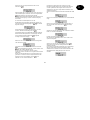
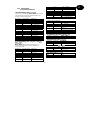
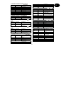
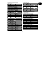
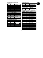
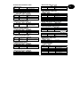
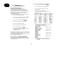
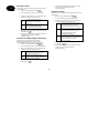
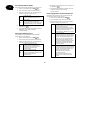
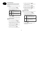
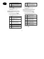
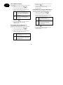
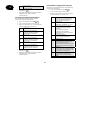
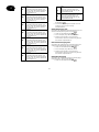
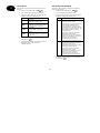
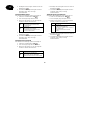
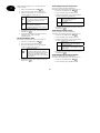
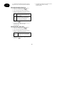
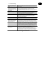
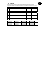
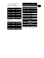
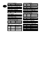
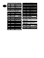
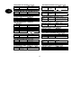
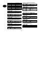
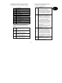
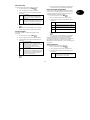
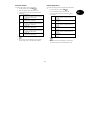
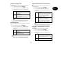
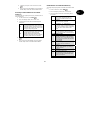
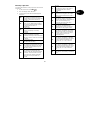
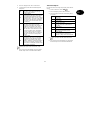
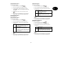
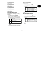
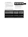
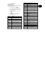
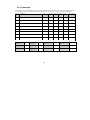
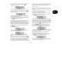
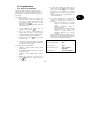
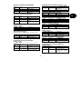
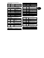
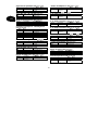
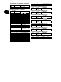
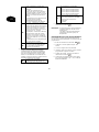
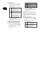
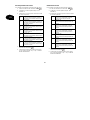
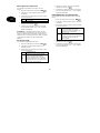
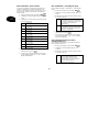
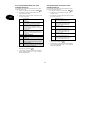
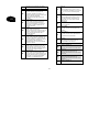
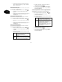
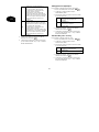
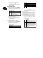
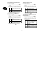
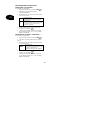
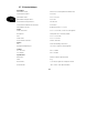
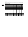
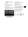
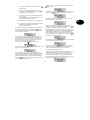
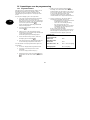
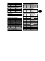
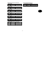
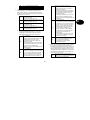
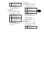
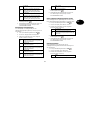
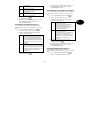
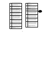
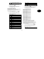
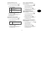
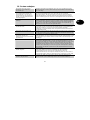
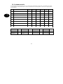
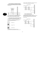
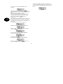
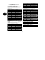
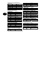
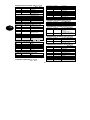
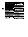
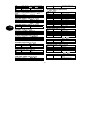
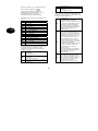
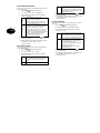
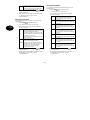
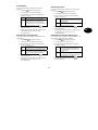
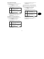
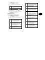
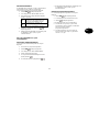
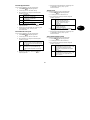
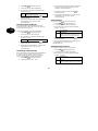
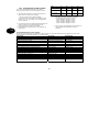
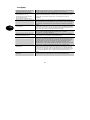
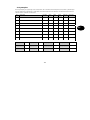
16.7 SIA Report-Modus
Modus = Grund
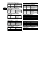
Ereignis SIA Code CID Code (1)
ALARM CONFIRM BV 139
BURG BA 130
BURG RESTORE BR 130‡
DURESS HA 121
EXIT TIMEOUT EA -
EXPANDER TAMPER TA 137
EXPANDER TAMPER RESTORE TR 137‡
FIRE FA 110
FIRE RESTORE FR 110‡
FORBI INTERFACE TAMPER TA 137
FORBI INTERFACE TAMPER RESTORE TR 137‡
FORBI LOOP TAMPER TA 137
FORBI LOOP TAMPER RESTORE TR 137‡
FORBI TAMPER TA 137
FORBI TAMPER RESTORE TR 137‡
GLOBAL TAMPER TA 137
GLOBAL TAMPER RESTORE TR 137‡
KEYBOX OPEN BA 150
KEYBOX CLOSED BR 150‡
KEYPAD MEDICAL MA 100
KEYPAD FIRE FC 110
KEYPAD PA HA 120
LID TAMPER TA 137
LID TAMPER RESTORE TR 137‡
MAN TRIGGER TEST REPORT RX 601
PANIC PA 120
PANIC RESTORE PR 120‡
PERIODIC TEST REPORT RP 602
SENSOR TAMPER TA 137
SENSOR TAMPER RESTORE TR 137‡
SMOKE DETECTOR FA 111
SMOKE DETECTOR RESTORE FR 111‡
BELL TAMPER TA 137
BELL TAMPER RESTORE TR 137‡
SUPERVISION FAIL BZ 381
TA (Technical Alarm) UA 150
TA RESTORE UR 150‡
TAMPER KEYPAD TA 137
TAMPER KEYPAD RESTORE TR -
TELCO1 FAULT LT 351
TELCO2 FAULT RESTORE LR -
ZONE OMIT BB 573

97
D
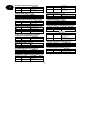
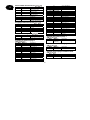
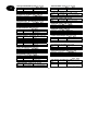
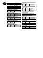
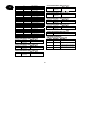
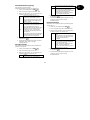
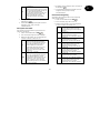
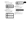
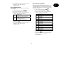
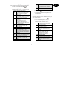
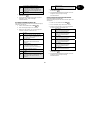
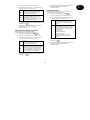
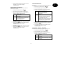
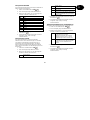
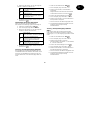
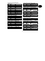
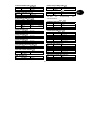
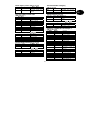
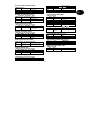
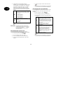
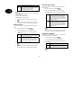
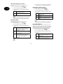
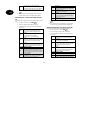
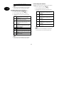
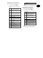
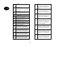
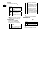
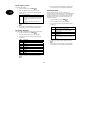
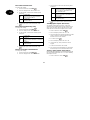
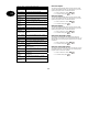
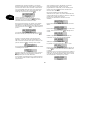
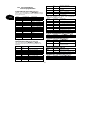
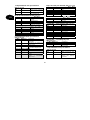
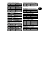
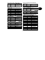
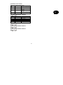
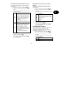
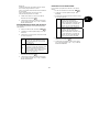
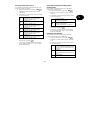
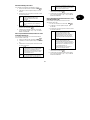
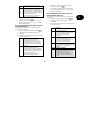
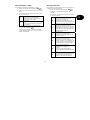
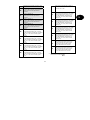
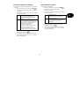
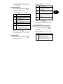
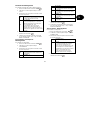
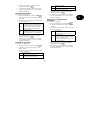
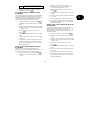
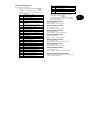
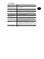
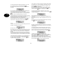
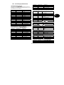
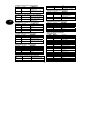
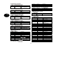
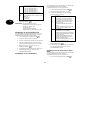
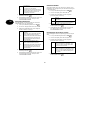
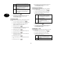
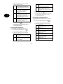
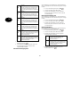
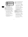
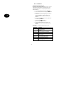
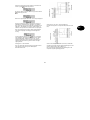
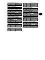
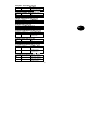
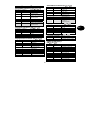
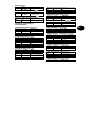
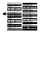
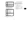
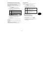
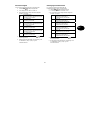
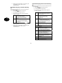
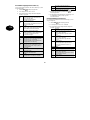
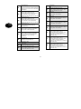
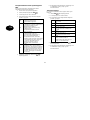
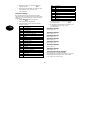
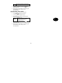
Modus = Zusammenfassung
Ereignis SIA Code CID Code
AC LOST AT 301
AC RESTORE AR 301‡
ALARM ABORT BC 406
ANTI MASK ZONE OPEN (2) BT 380
ANTI MASK ZONE TAMPER (2) BT 380
ANTI MASK ZONE RESTORED (2) BJ 380
AUX TROUBLE YP -
AUX RESTORED YQ -
BATT MISSING YM 311
BATT RESTORED YR 311‡
LOW BATT YT 311
LOW BATT RESTORE YR 311‡
PARTITION RESET OR 305
RESET OR 305
Modus = Zwischenmeldungen
Ereignis SIA Code CID Code
ARM CL 401
DISARM OP 401
KEYSWITCH DISARM OS 409
KEYSWITCH ARM CS 409
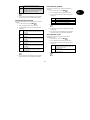
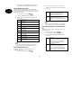
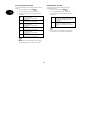
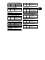
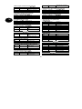
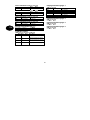
Modus = Total
Ereignis SIA Code CID Code
DOWNLOAD SUCCESS RS 412
EXPANDER MISSING TA 137
EXPANDER MISSING RESTORE TR 137‡
FORBI MISSING TA 137
FORBI MISSING RESTORE TR 137‡
JAMMING XQ 380
PASSWORD DEFAULTS LOADED RH -
PROG MODE START LB 627
PROG MODE END LS 628
TAMPER USER CODE JA 461
TD (Time and Day) RESET JT 625
TX BATTERY TROUBLE XT 384
USER CODE CHANGED JV -
USER CODE DELETED JX -
(1) Wenn Befehl 143=1 gesetzt ist, so werden alle CID Codes gesendet. Ist der Befehl 143=0 gesetzt, so werden alle
Befehle, die mit ‡ gekennzeichnet sind, nicht gesendet.
(2) Die Zentrale registriert ein Anti-Mask-Ereignis als einen Anti-Mask-Typ niedriger als dieser tatsächlich ist.
Page is loading ...
Page is loading ...
Page is loading ...
Page is loading ...
Page is loading ...
Page is loading ...
Page is loading ...

UK UK
Intruder alarm panel Terxon MX – Installation instructions
Perfect Security for
the home and the office
These installation instructions are an important product
accessory. They contain important installation and
operation information. Bear this in mind if you pass the
product on to others. Store these installation
instructions in a safe place for future reference.
For a list of contents with page numbers, see page 3.

UK UK
1 Introduction
Dear Customer,
Thank you for purchasing the Burglar Alarm Panel
Terxon MX. You have purchased a product that has been
designed and constructed according to the state-of-the-
art,
which complies with the current standards of domestic
and European regulations. The CE has been proven and
all related certifications are available from the
manufacturer upon request (www.abus-sc.eu).
To maintain this status and to guarantee safe operation, it
is your obligation to observe these installation instructions.
In the event of questions, please contact your local
specialist dealer.
ABUS Security-Center GmbH & Co. KG
86444 Affing
GERMANY
www.abus-sc.eu
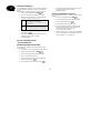
2 Usage in accordance with
regulations
This burglar alarm panel uses detectors and transmitters
to secure your property. You can use it to protect your
company, house, garage, garden house, weekend
cottage, etc.
The alarm centre registers unauthorised break-ins by
switching output contacts to which you can connect visual,
acoustic or silent alarm transmitters.
The alarm centre contacts and connected components
must be kept free of moisture (bathrooms and similar
surroundings are to be strictly avoided).
Use of this product for other than the described purpose
may lead to damage of the product.
Other hazards such as short-circuiting, fire, electric shock,
etc., are also possible. The power unit is designed for
operation with mains electricity at 230 Volt AC / 50 Hz.
No part of the product may changed or modified in any
way.
Connection to the public power network is subject to
country-specific regulations. Please be aware of
applicable regulations in advance.

3
UK
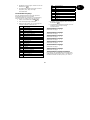
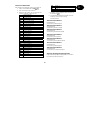
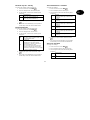
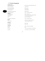
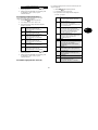
3 Contents
1 Introduction........................................................................................................................................2
2 Usage in accordance with regulations..............................................................................................2
3 Contents............................................................................................................................................3
4 Precautions........................................................................................................................................5
5 Scope of delivery and accessories required......................................................................................6
6 Notes on connection and extension options......................................................................................7
7 Notes on security system...................................................................................................................8
8 Overview of housing components....................................................................................................10
9 Notes on installation ........................................................................................................................12
9.1 Alarm centre.............................................................................................................................12
9.2 Control units .............................................................................................................................12
10 Notes on wiring................................................................................................................................13
10.1 Alarm centre.............................................................................................................................13
10.2 Control units .............................................................................................................................14
10.3 Detectors..................................................................................................................................16
10.3.1 Door and window contacts ................................................................................................16
10.3.2 Infrared se
nsitivity detector................................................................................................16
10.3.3 Smoke detector.................................................................................................................17
10.3.4 Acoustic glass breakage sensor:.......................................................................................17
10.3.5 Passive glass breakage sensor:........................................................................................17
10.4 Outdoor siren and flashlight......................................................................................................18
10.5 Dialler.......................................................................................................................................19
10.6 Key switch ................................................................................................................................19
10.7 Fitting and connecting a loudspeaker.......................................................................................20
10.8 Relay module............................................................................................................................20
10.9 Resistors ..................................................................................................................................20
10.10 Connecting expansion modules............................................................................................21
10.11 Addressing of expansion modules:.......................................................................................21
10.12 Walk test...............................................................................................................................21
10.13 Detector alarm memory ........................................................................................................21
11 Single system or partitioned system................................................................................................22
12 Term declaration..............................................................................................................................23
13 General terms..................................................................................................................................24
14 Specimen Installation
.......................................................................................................................25
15 First-time usage...............................................................................................................................31
16 Programming...................................................................................................................................32

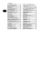
4
UK
16.1 Program mode..........................................................................................................................32
16.2 Overview of program menu ......................................................................................................33
16.3 Settings in program menu ........................................................................................................46
16.4 Programming Partitions............................................................................................................85
16.5 Examples for a partitioned system............................................................................................86
16.6 Test functions...........................................................................................................................87
16.7 SIA Report Mode......................................................................................................................90
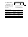
17 Technical data.................................................................................................................................92
18 Troubleshooting...............................................................................................................................93
19 Index of Programming Functions.....................................................................................................94
20 System plan.....................................................................................................................................96

5
UK
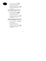
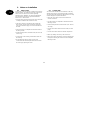
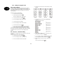
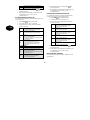
4 Precautions
!WARNING!
To avoid fire and injury, please
observe the following:
• Securely fasten the device at a
dry location in the building.
• Ensure sufficient air circulation for
the alarm centre.
• Do not expose the device to
temperatures less than -10°C or
more than 55°C.
• The device is designed for indoor
use only.
• Humidity must not exceed 90%
(non-condensed).
• Make sure that no metal objects
can be pushed into the equipment
from outside.
• Ensure that the voltage is
disconnected when performing
work on the device.
!ATTENTION!
Please observe the following
regulations to ensure trouble-free
operation of your device.
• The alarm centre is supplied with
12V DC power by means of the
internal transformer.
• The transformer is connected to
the 230VAC building mains by
means of a separate, electrically
protected line.
• Connection work to the building
mains is subject to country-
specific regulations.
• A 7Ah rechargeable battery
supplies emergency standby
power.
• The maximum power
consumption of connected
components must never exceed
1A.
• Always replace fuses with fuses
of the same rating, never higher.
!IMPORTANT INFO!
Burglar alarm panels in general:
If the equipment is not correctly
installed, signals may be
misinterpreted and result in false
alarms.The costs resulting from the
deployment of rescue organisations,
e.g.:fire or police, are borne by the
operator of the equipment.
Therefore please read the
instructions very carefully and follow
the installation instructions for lines
and components precisely.

6
UK
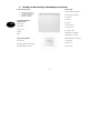
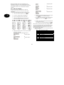
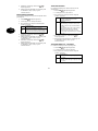
5 Scope of delivery and accessories required
Scope of delivery
• Intruder alarm panel
(“alarm centre”)
• LCD operating panel
• Installation Instructions
• Operating instructions
You also need:
Alarm detector
Signal transmitter
12V/7Ah rechargeable battery
Distributor
Cables
Optionally available:
Relay module
8-zone radio expansion unit
8-zone wire expansion
Required tools:
Flat screwdriver (small)
Philips screwdriver
Drill
6mm drill bit
4mm drill bit
6mm screws
4mm screws
Wallplugs, filler, etc.
Soldering iron and solder
Insulation tape or shrink-on tubing
Voltmeter, ohmmeter (or
multimeter)
Cable channel
Screw-clamps

7
UK
6 Notes on connection and extension options
The burglar alarm panel is the basic device of an
electronic security system for protecting your property
(e.g.: apartment, house, garage, shops, etc.). In
combination with other components such as detectors and
signal transmitters, it secures the areas to be monitored.
The alarm is triggered by unauthorised break-in attempts.
The alarm centre is operated by means of the connected
control unit. This enables the alarm centre to be installed
at a hidden location. Up to 4 control units can be
connected. Furthermore, the alarm centre can be
operated via a so-called key switch.
Due to the built-in telephone dialler, the burglar alarm
panel is able to transmit an alarm via the telephone
network to selected subscribers.
The burglar alarm panel has 9 separately evaluated alarm
zones. The alarm centre monitors whether a (minimal)
quiescent current is flowing or not between the two
contacts (CCT) of each alarm zone. If you make a contact
between the alarm zone contacts, this is treated as closed
and a current flow is possible. If no contact exists, no
current flow is possible and the alarm zone is open. Any
changes trigger an alarm, depending on the programming.
Differential monitoring of the alarm zones is also possible
(DEOL).
The alarm centre also has a built-in PC interface.
Properties of the alarm centre:
• 8 freely programmable alarm zones, all of which can be
programmed as follows:
Immediate, delayed, access, panic, 24 hour, fire,
technical or time
• Expandable to a maximum of 32 zones via optional
expansion modules
• 1 tamper zone for connected detectors
• 1 tamper zone for connected signal transmitters
• 1 transistor output and 2 relay outputs that can be
configured for a specific event (alarm, fire, panic,…)
• Integrated transformer (230V AC / 12V DC) for
supplying the alarm centre and connected detectors and
for recharging the battery
• Standby power supply via a 12V/7Ah battery
• Simple programming and operation via 1–4 control units
• The state of the alarm zones and the alarm centre is
displayed on a plain-text display.
• Zone blocking as a way of temporarily removing
individual alarm zones from surveillance
• Access authorisation for operating and programming
using a 4-digit or 6-digit code.
• Tamper contacts for the alarm centre and the control
units
• Alarm and event memory
• Integrated telephone dialler
• Partitioning of the alarm centre for simulation of 4
separate alarm centres

8
UK
7 Notes on security system
The Terxon MX burglar alarm panel enables you to
configure each of the 8 (max. 32) alarm zones
optimally to suit your operating conditions.
Recommendations:
• Distribute the external detectors in as small groups as
possible to the zones (e.g., ground-floor detector to
zone 1, etc.); activate detectors singly; if possible, use
all zones of the alarm centre.
• The acoustic signal (siren) of the signal transmitter
should be shorter than the visual signal (flashlight).
Alarm times must be set according to local regulations.
(E.g., in Germany, the acoustic alarm must be limited to
3 minutes.)
• The delay time should not be finally set until a practical
test has been conducted.
• Choose a random 4-digit or 6-digit combination for the
user and program code.
• Only persons of trust should be given the code.
• When operating the alarm centre, enter the code in such
a way that it is concealed from persons standing nearby.
• The cable recommended for connecting the
components (minimum diameter: 0.6 mm/wire) is
normally colour-coded.
The user and program codes must be different.
For reasons of clear layout, use the following colour
coding:
Red: +12V voltage supply
Black: 0V ground
Yellow: Alarm contact
Green: Alarm contact
Brown: Tamper contact
White: Tamper contact
• Use distributors when connecting more than one
detector to an alarm zone. Cable extensions can be
soldered or screwed together. Ensure good insulation
(insulating tape, shrink-on tubing) to avoid short-
circuiting and false alarms. See the illustration on the
next page.
• Proceed as follows:
1. Read the operating instructions carefully.
2. Draw up a plan of the object that includes the
installation location of the detectors and the alarm
centre and all cables required.
3. Lay the cables as required.
4. Install the detectors and the alarm centre.
5. Connect the cables to the detectors and the alarm
centre.
6. Connect the power supply (battery, mains).
7. Program the device.

9
UK
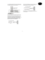
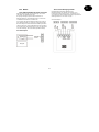
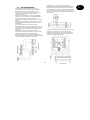
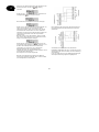
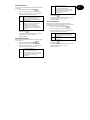
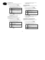
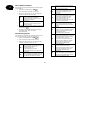
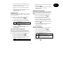
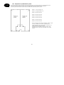
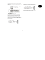
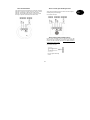
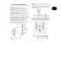
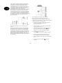
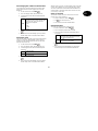
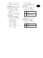
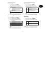
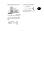
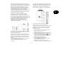
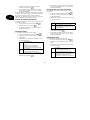
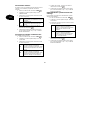
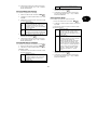
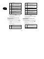
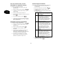
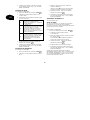
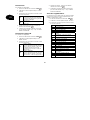
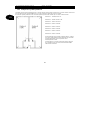
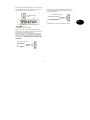
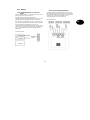
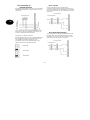
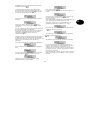
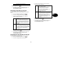
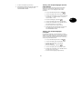
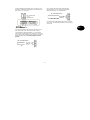
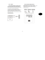
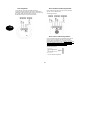
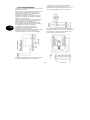
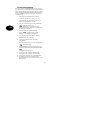
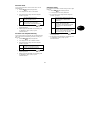
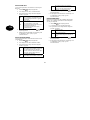
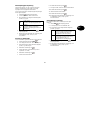
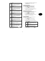
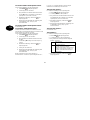
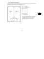
The diagram below shows the correct usage of soldered
distributors when connecting more than one detector to an
alarm zone:
As mentioned above, the alarm centre evaluates the
alarm zones via the existing current flow. Most alarm
detectors are normally closed, which means that the
detectors interrupt the alarm zone in the event of an
alarm. The detectors are called NC (normally closed)
detectors and are connected as follows (the CCT jumper
must be removed):
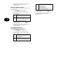
Sometimes it is necessary to combine several alarm
contacts in a zone. Connect the contacts serially.
NO (normally open) contacts (e.g., for panic buttons)
cannot be connected to this alarm centre.
Verteiler
NC-Alarmkontakt
(z.B. Öffnungsmelder)
A
nschlusskabel zur Zentrale
NC alarm contact
NC alarm contact
(e.g. contact switch
Connection cable to alarm centre
NC alarm contact

10
UK
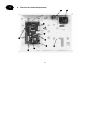
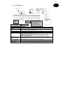
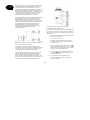
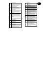
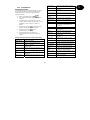
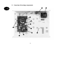
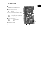
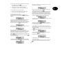
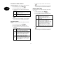
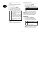
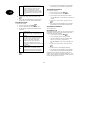
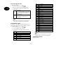
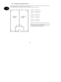
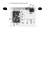
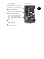
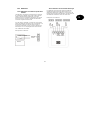
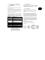
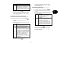
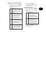
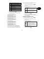
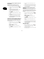
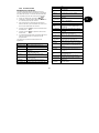
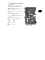
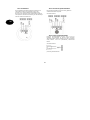
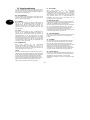
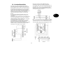
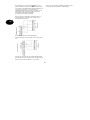
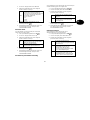
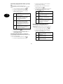
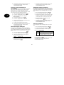
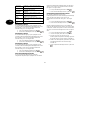
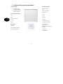
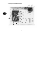
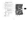
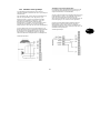
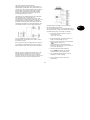
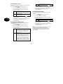
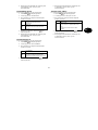
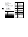
8 Overview of housing components
2
4
6
5
3
7
1
8
9

11
UK
Connection of 230V mains supply with primary fuse (T 250V 250mA).
230V AC / 12V DC transformer
Connector strip for siren, flashlight, programmable outputs, loudspeakers, 12VDC power supply and
alarm zones.
Connection of tamper contacts of the housing of the alarm centre.
Terminal connector strip for standby battery.
Terminal connector strip for control units.
Terminal connector strip for extra transistor outputs or the optional relay module.
Room for 12V standby battery (7Ah) and cabling.
9 Connection for PC data cable
Connections for telephone line
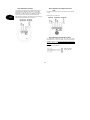
Note for 230 V connection
Do not switch on the mains power yet!
Connect the mains power to the terminal connector strip as follows:
neutral (blue)
Phase (black)
ground (green/yellow)
1
3
4
5
6
7
8
2

12
UK
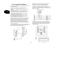
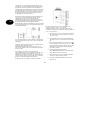
9 Notes on installation
9.1 Alarm centre
Fix the alarm centre to a flat, dry, vibration-free and heat-
resistant surface. The cables for the power supply of the
alarm centre, the alarm zones and the signalling
equipment (siren, flashlight, any external loudspeakers,
etc.) should be inconspicuous, if possible below the
surface or in a cable channel.
• Open the alarm centre housing (loosen the screws with
a Philips screwdriver and remove the cover).
• The alarm centre’s PCB is fixed in the housing with
three screws. Loosen these screws and remove the
PCB. The transformer plug can be disconnected from
the PCB.
• Use the housing as a template to make drill-marks for
the fixing-screws.
• At the marked positions, drill three holes (min. 4mm Ø,
4.5cm long).
• Fix the alarm centre housing and feed the cables into
the housing.
• Do not tighten the fixing screws until you have
connected all the cables. Replace the PCB and close
the housing by replacing the cover.
9.2 Control units
The control units should also be mounted on a flat, dry,
vibration-free surface. The mounting height is important.
The units should be positioned so that all users can easily
read the display and operate the buttons.
• Open the cover of the control unit and loosen the
screws on the base.
• Use the housing as a template to make drill-marks for
the fixing-screws.
• At the marked positions, drill three holes (min. 4mm Ø,
3cm long).
• Connect the control unit to the alarm centre (see next
page).
• Connect the control unit to the external components.
• Make any settings necessary in the control unit.
• Mount the control unit housing on the wall. Replace the
front plate containing the control unit PCB and tighten
the fixing screws.

13
UK
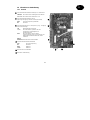
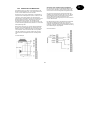
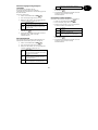
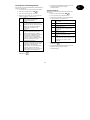
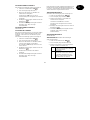
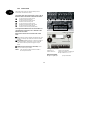
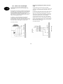
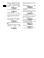
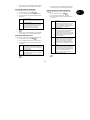
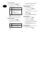
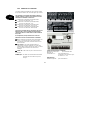
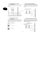
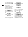
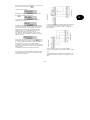
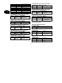
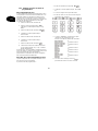
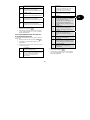
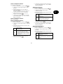
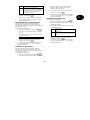
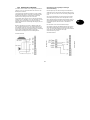
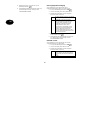
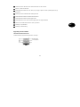
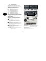
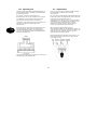
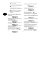
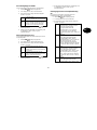
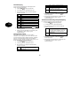
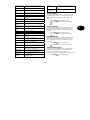
10 Notes on wiring
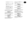
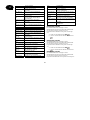
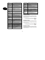
10.1 Alarm centre
Terminal connector strip for tamper and alarm zones.
COM A/T: Connections for detector tampering
CCT 1…8: Connections for alarm zones 1–8
Terminal connector strip for 12V DC power supply of
external equipment (e.g., detectors)
AUX: +12V permanent voltage for detectors
0V: 0V ground
Terminal connector strip for loudspeaker, progr. outputs and
siren tampering.
TR: Sabotage inputs
+ / LS: Contact for optional 16 Ohm loudspeaker
OP3: Contact for Open Collector Transistor output
(e.g. as trigger signal of dialler)
RELAY
OUTPUTS:Connections for 2 relays NC/NO
Terminal strip for control units
12V: 12V+ permanent voltage
0V: 0V ground
Data: Databus
Clock: Databus
5 Connection for PC data cable
6 Connections for telephone line
2
3
4
1
5
6
2
1
3
4

14
UK
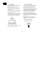
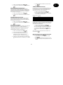
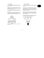
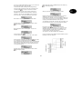
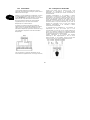
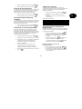
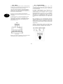
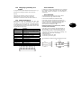
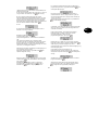
10.2 Control units
The burglar alarm panel can operate with up to four
control units connected via a BUS.
The control units can be connected as a ring or star to
the alarm centre. Connect the control unit as follows:
To next control unit / alarm centre
Terminal connector strip: 0V
To next control unit / alarm centre
Terminal connector strip: 12V
To next control unit / alarm centre
Terminal connector strip: CLK (Clock)
To next control unit / alarm centre
Terminal connector strip: DATA (Data)
The length of the databus must not exceed 200m. For
connecting the control units, use a cable with a wire
diameter of min. 0.6mm.
Other devices that can be connected to the control
units:
ET: A switch for manual ending of exit delay time. The
contact is normally open (NO) and must be closed to
activate.
Ext. Tamper: Additional input on control unit to which
an external tamper contact (NC) can be connected.
The contact must be opened to trigger a tamper
alarm.
PANIC I/P (from panel version 2.04.0151): There
you can connect a panic button.
1
2
3
4
5
6
7
NOTE: The connection cables must be inserted in
the clamps from above
.
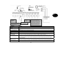
Coding of control units
Control unit 1: Jumper not connected
Control units 2–4: Jumper connected accordingly to
the pin numbers 2, 3, or 4.
Background lighting
Background lighting on: Jumper connected.
coding of control units
background lighting
volume beeper
tamper contact
beeper
1
2
3
4
5
6
7

15
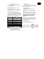
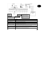
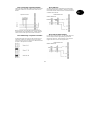
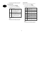
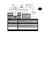
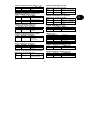
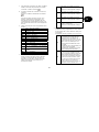
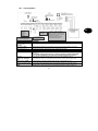
UK
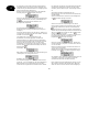
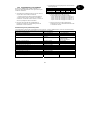
Connection
Meaning
AC mains supply unit (AC IN) Contact for 230V main supply unit
Kick Start jumper (KS) Connect the two contacts of this jumper to start the alarm centre without a 230V mains power
supply.
Battery contact (+ -) Connecting plug from standby power supply
COMMS interface Contact for additional transistor outputs
Reset jumper (NVM RST) Connect the two contacts of this jumper to reset the alarm centre.
Fuses (BAT F-2A / 12VAUX
F-1A)
Always use fuses of the same type. To avoid problems, make sure there is always a good
contact between the fuse holder and the fuse.
Siren sabotage input (TR) For sirens with their own power supply, connect this input direct to the tamper output of the
siren. Otherwise, connect the tamper contact of the siren to the loop between the TR input
and 0V. If no siren is used, connect the TR input direct to the 0V output.
Optional loudspeaker (LS) Connect a 16 Ohm loudspeaker for internal alerts.
Local download connection
(SK1)
You can connect a local PC here. The alarm centre can be configured using the downloader
program.
Connection for the telephone
connection (RJ11 + A/B /
A1/B1)
RJ11 connection/screw connections for the telephone line
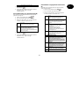
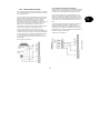
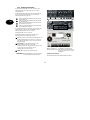
Programmable transistor output (OP).
Max. power consumption of all
transistor outputs 0.5A.
12V power supply for
components (e.g.
Tamper input for
ext. components
A
larm zones 1
–
8 for NC aöarm contact
(e.g. IR detector). No NO contacts can be
connected. Make sure alarm zones are
terminated with correct resistors. Two
different resistors, or no resistor, must be
used depending on the programming. If the
zone is used then the wire bridge should be
removed.
Sir.tamper input
Optional speaker
control unit
1A AUX fuse for
the power supply
2A BAT fuse for the
battery charging
A
C
connectio
Kick
Star
Battery
connectio
COM
interface
NVM
EEPROM
tamper cover
contact
Local
Download
-
connectio
Connection for
telephone
connection
Programmable
floating relay
output (NC/NO) /
24VDC@1A

16
UK
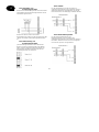
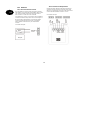
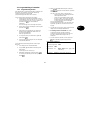
10.3 Detectors
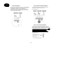
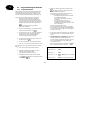
10.3.1 Door and window contacts
Door and window contacts monitor the opening of doors
and windows. To activate the entry/exit delay time, at least
one contact should be mounted on the main entrance
door on which a control unit is also mounted.
For transparency reasons, no more than ten door/window
contacts should be used per alarm zone. If the magnet of
the reed contact of the detector is removed, the switch
contact is opened and the alarm zone is interrupted.
Please read the instructions for your door/window
contacts.
Connection example:
10.3.2 Infrared sensitivity detector
Infrared sensitivity detectors detect the infrared heat
movement of living creatures and must not be used
indoors. For transparency reasons, avoid using motion
sensors with door/window contacts in a zone.
Connection example:
Reed
Ma
g
net

17
UK
10.3.3 Smoke detector
This burglar alarm panel allows the connection of smoke
detectors. For these, program zone type “fire” or “smoke
detector”, depending on the function of the smoke
detector. This programming result in a special acoustic
warning for persons present (pulsed alarm tone).
10.3.4 Acoustic glass breakage sensor:
These glass breakage sensors evaluate acoustic signals
resulting from glass breakage.
Connection example:
10.3.5 Passive glass breakage sensor:
Passive glass breakage sensors are fixed direct to the
glass pane to be monitored. Only passive glass breakage
sensors can be used that require no line feed but offer a
potential-free alarm contact.
Connection example:
Passive glass breakage
sensor

18
UK
10.4 Outdoor siren and flashlight
To deter burglars and alert the neighbourhood, we
recommend connecting a siren and a flashlight to the
alarm centre.
Note that these alarm devices should be mounted as high
as possible (e.g. at roof height) and the cables should not
be visible. Outdoor acoustic alarms can be a disturbance
to the neighbourhood. Observe country-specific
regulations. We recommend a maximum alarm duration of
three minutes. A visual alarm (flashlight) remains active
until it is acknowledged manually.
In addition to a siren and flashlight, we recommend
connecting the tamper contact of the combination
signalling device to the tamper input of the alarm centre. If
the siren housing is opened or the connection broken, the
interrupted tamper contact triggers a tamper alarm.
Connection example:
Connecting a signalling device with its own power
supply
The functioning principle of this alarm signalling
combination is based on a permanent power supply of the
siren and a rechargeable battery integrated in the siren
housing.
At a transistor output of the alarm centre, either a bias for
the siren is applied that is removed in the event of an
alarm (or is cut in the event of tampering), or the alarm
centre issues a trigger signal on alarm via the transistor
output that activates the siren and the flashlight.
The alarm duration of the siren is set on the signalling
equipment direct. Here too, the flashlight remains active
until it is acknowledged manually. For correct installation,
please read the installation instructions of the signalling
device with own power supply.
Connection example:
max. 500mA
max. 500mA
Alarm centre
signaling
di
Page is loading ...
Page is loading ...
Page is loading ...
Page is loading ...
Page is loading ...
Page is loading ...
Page is loading ...
Page is loading ...
Page is loading ...
Page is loading ...
Page is loading ...
Page is loading ...
Page is loading ...
Page is loading ...
Page is loading ...
Page is loading ...
Page is loading ...
Page is loading ...
Page is loading ...
Page is loading ...
Page is loading ...
Page is loading ...
Page is loading ...
Page is loading ...
Page is loading ...
Page is loading ...
Page is loading ...
Page is loading ...
Page is loading ...
Page is loading ...
Page is loading ...
Page is loading ...
Page is loading ...
Page is loading ...
Page is loading ...
Page is loading ...
Page is loading ...
Page is loading ...
Page is loading ...
Page is loading ...
Page is loading ...
Page is loading ...
Page is loading ...
Page is loading ...
Page is loading ...
Page is loading ...
Page is loading ...
Page is loading ...
Page is loading ...
Page is loading ...
Page is loading ...
Page is loading ...
Page is loading ...
Page is loading ...
Page is loading ...
Page is loading ...
Page is loading ...
Page is loading ...
Page is loading ...
Page is loading ...
Page is loading ...
Page is loading ...
Page is loading ...
Page is loading ...
Page is loading ...
Page is loading ...
Page is loading ...
Page is loading ...
Page is loading ...
Page is loading ...
Page is loading ...
Page is loading ...
Page is loading ...
Page is loading ...
Page is loading ...
Page is loading ...
Page is loading ...
Page is loading ...
Page is loading ...
Page is loading ...
Page is loading ...
Page is loading ...
Page is loading ...
Page is loading ...
Page is loading ...
Page is loading ...
Page is loading ...
Page is loading ...
Page is loading ...
Page is loading ...
Page is loading ...
Page is loading ...
Page is loading ...
Page is loading ...
Page is loading ...
Page is loading ...
Page is loading ...
Page is loading ...
Page is loading ...
Page is loading ...
Page is loading ...
Page is loading ...
Page is loading ...
Page is loading ...
Page is loading ...
Page is loading ...
Page is loading ...
Page is loading ...
Page is loading ...
Page is loading ...
Page is loading ...
Page is loading ...
Page is loading ...
Page is loading ...
Page is loading ...
Page is loading ...
Page is loading ...
Page is loading ...
Page is loading ...
Page is loading ...
Page is loading ...
Page is loading ...
Page is loading ...
Page is loading ...
Page is loading ...
Page is loading ...
Page is loading ...
Page is loading ...
Page is loading ...
Page is loading ...
Page is loading ...
Page is loading ...
Page is loading ...
Page is loading ...
Page is loading ...
Page is loading ...
Page is loading ...
Page is loading ...
Page is loading ...
Page is loading ...
Page is loading ...
Page is loading ...
Page is loading ...
Page is loading ...
Page is loading ...
Page is loading ...
Page is loading ...
Page is loading ...
Page is loading ...
Page is loading ...
Page is loading ...
Page is loading ...
Page is loading ...
Page is loading ...
Page is loading ...
Page is loading ...
Page is loading ...
Page is loading ...
Page is loading ...
Page is loading ...
Page is loading ...
Page is loading ...
Page is loading ...
Page is loading ...
Page is loading ...
Page is loading ...
Page is loading ...
Page is loading ...
Page is loading ...
Page is loading ...
Page is loading ...
Page is loading ...
Page is loading ...
Page is loading ...
Page is loading ...
Page is loading ...
Page is loading ...
Page is loading ...
Page is loading ...
Page is loading ...
Page is loading ...
Page is loading ...
Page is loading ...
Page is loading ...
Page is loading ...
Page is loading ...
Page is loading ...
Page is loading ...
Page is loading ...
Page is loading ...
Page is loading ...
Page is loading ...
Page is loading ...
Page is loading ...
Page is loading ...
Page is loading ...
Page is loading ...
Page is loading ...
Page is loading ...
Page is loading ...
Page is loading ...
Page is loading ...
Page is loading ...
Page is loading ...
Page is loading ...
Page is loading ...
Page is loading ...
Page is loading ...
Page is loading ...
Page is loading ...
Page is loading ...
Page is loading ...
Page is loading ...
Page is loading ...
Page is loading ...
Page is loading ...
Page is loading ...
Page is loading ...
Page is loading ...
Page is loading ...
Page is loading ...
Page is loading ...
Page is loading ...
Page is loading ...
Page is loading ...
Page is loading ...
Page is loading ...
Page is loading ...
Page is loading ...
Page is loading ...
Page is loading ...
Page is loading ...
Page is loading ...
Page is loading ...
Page is loading ...
Page is loading ...
Page is loading ...
Page is loading ...
Page is loading ...
Page is loading ...
Page is loading ...
Page is loading ...
Page is loading ...
Page is loading ...
Page is loading ...
Page is loading ...
Page is loading ...
Page is loading ...
Page is loading ...
Page is loading ...
Page is loading ...
Page is loading ...
Page is loading ...
Page is loading ...
Page is loading ...
Page is loading ...
Page is loading ...
Page is loading ...
Page is loading ...
Page is loading ...
Page is loading ...
Page is loading ...
Page is loading ...
Page is loading ...
Page is loading ...
Page is loading ...
Page is loading ...
Page is loading ...
Page is loading ...
Page is loading ...
Page is loading ...
Page is loading ...
Page is loading ...
Page is loading ...
Page is loading ...
Page is loading ...
Page is loading ...
Page is loading ...
Page is loading ...
Page is loading ...
Page is loading ...
Page is loading ...
Page is loading ...
Page is loading ...
Page is loading ...
Page is loading ...
Page is loading ...
Page is loading ...
Page is loading ...
Page is loading ...
Page is loading ...
Page is loading ...
Page is loading ...
Page is loading ...
Page is loading ...
Page is loading ...
Page is loading ...
Page is loading ...
Page is loading ...
Page is loading ...
Page is loading ...
Page is loading ...
Page is loading ...
Page is loading ...
Page is loading ...
Page is loading ...
Page is loading ...
Page is loading ...
Page is loading ...
Page is loading ...
Page is loading ...
Page is loading ...
Page is loading ...
Page is loading ...
Page is loading ...
Page is loading ...
Page is loading ...
Page is loading ...
Page is loading ...
Page is loading ...
Page is loading ...
Page is loading ...
Page is loading ...
Page is loading ...
Page is loading ...
Page is loading ...
Page is loading ...
Page is loading ...
Page is loading ...
Page is loading ...
Page is loading ...
Page is loading ...
Page is loading ...
Page is loading ...
Page is loading ...
Page is loading ...
Page is loading ...
Page is loading ...
Page is loading ...
Page is loading ...
Page is loading ...
Page is loading ...
Page is loading ...
Page is loading ...
Page is loading ...
Page is loading ...
Page is loading ...
Page is loading ...
Page is loading ...
Page is loading ...
Page is loading ...
Page is loading ...
Page is loading ...
Page is loading ...
Page is loading ...
Page is loading ...
Page is loading ...
Page is loading ...
Page is loading ...
Page is loading ...
Page is loading ...
Page is loading ...
-
 1
1
-
 2
2
-
 3
3
-
 4
4
-
 5
5
-
 6
6
-
 7
7
-
 8
8
-
 9
9
-
 10
10
-
 11
11
-
 12
12
-
 13
13
-
 14
14
-
 15
15
-
 16
16
-
 17
17
-
 18
18
-
 19
19
-
 20
20
-
 21
21
-
 22
22
-
 23
23
-
 24
24
-
 25
25
-
 26
26
-
 27
27
-
 28
28
-
 29
29
-
 30
30
-
 31
31
-
 32
32
-
 33
33
-
 34
34
-
 35
35
-
 36
36
-
 37
37
-
 38
38
-
 39
39
-
 40
40
-
 41
41
-
 42
42
-
 43
43
-
 44
44
-
 45
45
-
 46
46
-
 47
47
-
 48
48
-
 49
49
-
 50
50
-
 51
51
-
 52
52
-
 53
53
-
 54
54
-
 55
55
-
 56
56
-
 57
57
-
 58
58
-
 59
59
-
 60
60
-
 61
61
-
 62
62
-
 63
63
-
 64
64
-
 65
65
-
 66
66
-
 67
67
-
 68
68
-
 69
69
-
 70
70
-
 71
71
-
 72
72
-
 73
73
-
 74
74
-
 75
75
-
 76
76
-
 77
77
-
 78
78
-
 79
79
-
 80
80
-
 81
81
-
 82
82
-
 83
83
-
 84
84
-
 85
85
-
 86
86
-
 87
87
-
 88
88
-
 89
89
-
 90
90
-
 91
91
-
 92
92
-
 93
93
-
 94
94
-
 95
95
-
 96
96
-
 97
97
-
 98
98
-
 99
99
-
 100
100
-
 101
101
-
 102
102
-
 103
103
-
 104
104
-
 105
105
-
 106
106
-
 107
107
-
 108
108
-
 109
109
-
 110
110
-
 111
111
-
 112
112
-
 113
113
-
 114
114
-
 115
115
-
 116
116
-
 117
117
-
 118
118
-
 119
119
-
 120
120
-
 121
121
-
 122
122
-
 123
123
-
 124
124
-
 125
125
-
 126
126
-
 127
127
-
 128
128
-
 129
129
-
 130
130
-
 131
131
-
 132
132
-
 133
133
-
 134
134
-
 135
135
-
 136
136
-
 137
137
-
 138
138
-
 139
139
-
 140
140
-
 141
141
-
 142
142
-
 143
143
-
 144
144
-
 145
145
-
 146
146
-
 147
147
-
 148
148
-
 149
149
-
 150
150
-
 151
151
-
 152
152
-
 153
153
-
 154
154
-
 155
155
-
 156
156
-
 157
157
-
 158
158
-
 159
159
-
 160
160
-
 161
161
-
 162
162
-
 163
163
-
 164
164
-
 165
165
-
 166
166
-
 167
167
-
 168
168
-
 169
169
-
 170
170
-
 171
171
-
 172
172
-
 173
173
-
 174
174
-
 175
175
-
 176
176
-
 177
177
-
 178
178
-
 179
179
-
 180
180
-
 181
181
-
 182
182
-
 183
183
-
 184
184
-
 185
185
-
 186
186
-
 187
187
-
 188
188
-
 189
189
-
 190
190
-
 191
191
-
 192
192
-
 193
193
-
 194
194
-
 195
195
-
 196
196
-
 197
197
-
 198
198
-
 199
199
-
 200
200
-
 201
201
-
 202
202
-
 203
203
-
 204
204
-
 205
205
-
 206
206
-
 207
207
-
 208
208
-
 209
209
-
 210
210
-
 211
211
-
 212
212
-
 213
213
-
 214
214
-
 215
215
-
 216
216
-
 217
217
-
 218
218
-
 219
219
-
 220
220
-
 221
221
-
 222
222
-
 223
223
-
 224
224
-
 225
225
-
 226
226
-
 227
227
-
 228
228
-
 229
229
-
 230
230
-
 231
231
-
 232
232
-
 233
233
-
 234
234
-
 235
235
-
 236
236
-
 237
237
-
 238
238
-
 239
239
-
 240
240
-
 241
241
-
 242
242
-
 243
243
-
 244
244
-
 245
245
-
 246
246
-
 247
247
-
 248
248
-
 249
249
-
 250
250
-
 251
251
-
 252
252
-
 253
253
-
 254
254
-
 255
255
-
 256
256
-
 257
257
-
 258
258
-
 259
259
-
 260
260
-
 261
261
-
 262
262
-
 263
263
-
 264
264
-
 265
265
-
 266
266
-
 267
267
-
 268
268
-
 269
269
-
 270
270
-
 271
271
-
 272
272
-
 273
273
-
 274
274
-
 275
275
-
 276
276
-
 277
277
-
 278
278
-
 279
279
-
 280
280
-
 281
281
-
 282
282
-
 283
283
-
 284
284
-
 285
285
-
 286
286
-
 287
287
-
 288
288
-
 289
289
-
 290
290
-
 291
291
-
 292
292
-
 293
293
-
 294
294
-
 295
295
-
 296
296
-
 297
297
-
 298
298
-
 299
299
-
 300
300
-
 301
301
-
 302
302
-
 303
303
-
 304
304
-
 305
305
-
 306
306
-
 307
307
-
 308
308
-
 309
309
-
 310
310
-
 311
311
-
 312
312
-
 313
313
-
 314
314
-
 315
315
-
 316
316
-
 317
317
-
 318
318
-
 319
319
-
 320
320
-
 321
321
-
 322
322
-
 323
323
-
 324
324
-
 325
325
-
 326
326
-
 327
327
-
 328
328
-
 329
329
-
 330
330
-
 331
331
-
 332
332
-
 333
333
-
 334
334
-
 335
335
-
 336
336
-
 337
337
-
 338
338
-
 339
339
-
 340
340
-
 341
341
-
 342
342
-
 343
343
-
 344
344
-
 345
345
-
 346
346
-
 347
347
-
 348
348
-
 349
349
-
 350
350
-
 351
351
-
 352
352
-
 353
353
-
 354
354
-
 355
355
-
 356
356
-
 357
357
-
 358
358
-
 359
359
-
 360
360
-
 361
361
-
 362
362
-
 363
363
-
 364
364
-
 365
365
-
 366
366
-
 367
367
-
 368
368
-
 369
369
-
 370
370
-
 371
371
-
 372
372
-
 373
373
-
 374
374
-
 375
375
-
 376
376
-
 377
377
-
 378
378
-
 379
379
-
 380
380
-
 381
381
-
 382
382
-
 383
383
-
 384
384
-
 385
385
-
 386
386
-
 387
387
-
 388
388
-
 389
389
-
 390
390
-
 391
391
-
 392
392
-
 393
393
-
 394
394
-
 395
395
-
 396
396
-
 397
397
-
 398
398
-
 399
399
-
 400
400
-
 401
401
-
 402
402
-
 403
403
-
 404
404
-
 405
405
-
 406
406
-
 407
407
-
 408
408
-
 409
409
-
 410
410
-
 411
411
-
 412
412
-
 413
413
-
 414
414
-
 415
415
-
 416
416
-
 417
417
-
 418
418
-
 419
419
-
 420
420
-
 421
421
-
 422
422
-
 423
423
-
 424
424
-
 425
425
-
 426
426
-
 427
427
-
 428
428
-
 429
429
-
 430
430
-
 431
431
-
 432
432
-
 433
433
-
 434
434
-
 435
435
-
 436
436
-
 437
437
-
 438
438
-
 439
439
-
 440
440
-
 441
441
-
 442
442
-
 443
443
-
 444
444
-
 445
445
-
 446
446
-
 447
447
-
 448
448
-
 449
449
-
 450
450
-
 451
451
-
 452
452
-
 453
453
-
 454
454
-
 455
455
-
 456
456
-
 457
457
-
 458
458
-
 459
459
-
 460
460
-
 461
461
-
 462
462
-
 463
463
-
 464
464
-
 465
465
-
 466
466
-
 467
467
-
 468
468
-
 469
469
-
 470
470
-
 471
471
-
 472
472
-
 473
473
-
 474
474
-
 475
475
-
 476
476
-
 477
477
-
 478
478
-
 479
479
-
 480
480
-
 481
481
-
 482
482
-
 483
483
-
 484
484


Abus 4043158015706 User manual
- Category
- Security access control systems
- Type
- User manual
Ask a question and I''ll find the answer in the document
Finding information in a document is now easier with AI
in other languages
- français: Abus 4043158015706 Manuel utilisateur
- Deutsch: Abus 4043158015706 Benutzerhandbuch
- Nederlands: Abus 4043158015706 Handleiding
- dansk: Abus 4043158015706 Brugermanual
Related papers
-
Philips Terxon SX AZ4000 Technical data
-
Abus 4043158015690 Installation guide
-
Abus 4043158054538 Owner's manual
-
Abus AZ4130 Datasheet
-
Abus 4043158015690 Owner's manual
-
-
-
-
-
Abus BW8040 Specification
Other documents
-
Trebs MT-066 Datasheet
-
Tyco HS2TCHP E User manual
-
Cooper Scantronic 9448 User manual
-
Cooper Hand Tools Scantronic 9448 User manual
-
Renkforce MAC-608 Owner's manual
-
DSC PowerSeries User manual
-
-
 quiko QK-TXTRC User manual
-
Johnson Controls HS2TCHP User manual
-
Hama 00104986 Owner's manual
