
Installation Guide
DEVIlink™ FT
Floor thermostat
www.DEVI.com

DEVIlink™ FT
Installation Guide2
1 Introduction � � � � � � � � � � � � � � � � � � � � � 3
2 Placement of DEVIlink™ FT � � � � � � � � � � � � 4
2.1 Operation mode . . . . . . . . . . . . . . . . 4
2.2 Sensor combination. . . . . . . . . . . . . . 4
3 Installation of DEVIlink™ FT � � � � � � � � � � � 6
3.1 Configuration . . . . . . . . . . . . . . . . . . 7
4 Factory reset a DEVIlink™ FT � � � � � � � � � � � 7
5 Technical specifications � � � � � � � � � � � � � � 7
6 Radio Equipment Directive � � � � � � � � � � � 9
7 Warranty� � � � � � � � � � � � � � � � � � � � � � � � 9
8 Disposal instructions� � � � � � � � � � � � � � � 10
Table of Contents

DEVIlink™ FT
3Installation Guide
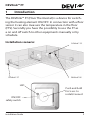
1 Introduction
The DEVIlink™ FT (Floor Thermostat) is a device for switch-
ing the heating element ON/OFF. In connection with a floor
sensor it can also measure the temperature in the floor
(FTS). Secondly you have the possibility to use the FT as
a on and off switch to other equipments manually or by
schedule.
Installation scenario:
DEVIlink™ CC
DEVIlink™ RS
DEVIlink™ FT
ON/OFF
safety switch
LED
Push and hold
for 5 sec. to
install/connect

DEVIlink™ FT
Installation Guide4
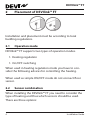
2 Placement of DEVIlink™ FT
Installation and placement must be according to local
building regulations.
2�1 Operation mode
DEVIlink™ FT supports two types of operation modes.
1. Heating regulation
1. On/OFF switching
When used in heating regulation mode you have to con-
sider the following advices for controlling the heating.
When used as simple ON/OFF mode do not connect floor
sensor.
2�2 Sensor combination
When installing the DEVIlink™ FT you need to consider the
type of heating and thus which sensors should be used.
There are three options:

DEVIlink™ FT
5Installation Guide
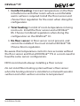
1. Comfort heating: Constant temperature on the floor
in bathrooms and other rooms where a comfortable
warm surface is required. Install the Floor sensor and
choose Floor regulation for the room when doing the
configuration.
2. Total heating: Control of room temperature in living
rooms etc. Install the floor sensor and a DEVIlink™
RS. Choose Combined regulation when doing the
configuration on the DEVIlink™ CC.
3. No floor sensor: A floor sensor is not present, and
cannot be installed. You must install a DEVIlink™ RS.
Choose Room regulation.
Be aware that temperature control is less accurate without
the floor sensor and that all DEVIlink™ FTs in a room need to
havethe same sensor configuration.
DEVI recommends always installing a floor sensor.
Do not install floor heating system without a floor sensor
when the heating element is installed on or beneath wooden
surfaces and other surfaces sensitive to temperature!

DEVIlink™ FT
Installation Guide6
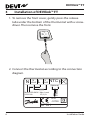
3 Installation of DEVIlink™ FT
1. To remove the front cover, gently press the release
tabs under the bottom of the thermostat with a screw-
driver. Then remove the front.
15
20
25
30
35
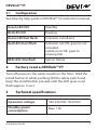
2. Connect the thermostat according to the connection
diagram.
DFT01
Sensor
N L
NTC
N
LOAD
L
LOAD
(Optional)
Mains 220-240V
50-60 Hz
Max. Load
15 (1) A
IP31
-10T30

DEVIlink™ FT
7Installation Guide
3�1 Configuration
See Step-by-Step guide in DEVIlink™ CC instruction manual.
Green LED ON Standby
Red LED ON Heating
Green LED fast flash Inclusion or link test
Red LED short flash Inclusion not OK, goes to not
included.
Linktest not OK, goes to
missing link
RED LED slow flash Sensor failure
4 Factory reset a DEVIlink™ FT
Turn off power on the safety switch on the front. Hold the
install button in while pushing ON the safety switch and
keep the install button pressed until the LED gives a red
flash (approx. 5 sec.)
5 Technical specifications
Operation voltage 180-250 VAC, 50/60 Hz
Standby power
consumption
Max. 1 W

DEVIlink™ FT
Installation Guide8
Relay:
• Resistive load
• Inductive load
230 V ~ 15 A / 3450 W
cos ϕ = 0.3 Max. 1 A
Sensing unit NTC 15 kOhm at 25°C
Sensing values:
• 0°C
• 20°C
• 50°C
42 kOhm
18 kOhm
6 kOhm
Regulation PWM
Ambient temperature -10° to +30°C
Sensor failure
monitoring
The thermostat has a built-
in monitoring circuit, which
will switch off the heating if
the sensor is disconnected
or short-circuited
Transmission frequency 868.42 MHz
Transmission range in
normal buildings
Up to 30 m
Transmission power Max. 1 mW
IP class 31
Dimensions 85 mm × 85 mm × 21 mm

DEVIlink™ FT
9Installation Guide
6 Radio Equipment Directive
SIMPLIFIED EU DECLARATION OF CONFORMITY
Hereby, Danfoss A/S declares that the radio equipment type
DEVIlink™ FT is in compliance with Directive 2014/53/EU
The full text of the EU declaration of conformity is available
at the following internet address: devi�danfoss�com
7 Warranty

DEVIlink™ FT
Installation Guide10
8 Disposal instructions

DEVIlink™ FT
11Installation Guide Produced by Danfoss © 06/201708095924 & VICKB502
Danfoss A/S
Electric Heating Systems
Ulvehavevej 61
7100 Vejle
Denmark
Phone: +45 7488 8500
Fax: +45 7488 8501
E-mail: [email protected]
Web: www.DEVI.com
Danfoss can accept no responsibility for possible errors in catalogues, brochures and other printed material. Danfoss
reserves the right to alter its products without notice. This also applies to products already on order provided that
such alterations can be made without subsequential changes being necessary in specifications already agreed. All
trademarks in this material are property of the respective companies. DEVI and the DEVI logo-type are trademarks of
Danfoss A/S. All rights reserved

DEVIlink™ FT
Installation Guide12
-
 1
1
-
 2
2
-
 3
3
-
 4
4
-
 5
5
-
 6
6
-
 7
7
-
 8
8
-
 9
9
-
 10
10
-
 11
11
-
 12
12


Ask a question and I''ll find the answer in the document
Finding information in a document is now easier with AI
Related papers
-
Danfoss 140F1137 Installation guide
-
-
Danfoss DEVIlink™ CC Operating instructions
-
-
-
-
-
-
-
Danfoss 140F1085 Installation guide
