Unbranded DS4(B,Q)D-KB/KC Installation guide

Category
Split-system air conditioners
Type
Installation guide

The Unbranded DS4(B,Q)D-KB/KC is a split system air conditioner designed for manufactured housing, offering efficient cooling and heating solutions. With its 13 SEER rating, it ensures energy savings while maintaining a comfortable indoor environment. It comes in various tonnage options, including 2, 2.5, 3, 3.5, 4, and 5 tons, allowing you to choose the right capacity for your space.

The Unbranded DS4(B,Q)D-KB/KC is a split system air conditioner designed for manufactured housing, offering efficient cooling and heating solutions. With its 13 SEER rating, it ensures energy savings while maintaining a comfortable indoor environment. It comes in various tonnage options, including 2, 2.5, 3, 3.5, 4, and 5 tons, allowing you to choose the right capacity for your space.

S4QD SERIES SPLIT SYSTEM AIR CONDITIONER FOR MANUFACTURED HOUSING
INSTALLATION INSTRUCTIONS
DO NOT DESTROY. PLEASE READ CAREFULLY AND
KEEP IN A SAFE PLACE FOR FUTURE REFERENCE.
IMPORTANT
ATTENTION INSTALLERS:
Please read all instructions before servicing this
equipment. Pay attention to all safety warnings
and any other special notes highlighted in the
manual. Safety markings are used frequently
throughout this manual to designate a degree or
level of seriousness and should not be ignored.
WARNING indicates a potentially hazardous
situation that if not avoided, could result in personal
injury or death.
CAUTION indicates a potentially hazardous
situation that if not avoided, may result in minor
or moderate injury or property damage.
It is your responsibility to know this product better
than your customer. This includes being able
to install the product according to strict safety
guidelines and instructing the customer on how
to operate and maintain the equipment for the
life of the product. Safety should always be the
deciding factor when installing this product and
using common sense plays an important role as
well. Pay attention to all safety warnings and any
other special notes highlighted in the manual.
Improper installation of the furnace or failure to
follow safety warnings could result in serious injury,
death, or property damage.
These instructions are primarily intended to assist
qualified individuals experienced in the proper
installation of this appliance. Some local codes
require licensed installation/service personnel for
this type of equipment. Please read all instructions
carefully before starting the installation. Return
these instructions to the customer’s package for
future reference.
IMPORTANT SAFETY INFORMATION .................2
AIR CONDITIONER INSTALLATION ....................3
General Information ..............................................3
Before You Install this Unit .....................................3
Locating the Air conditioner...................................3
Packaging Removal ..............................................3
Ground Level .........................................................3
Roof Mount............................................................3
Connecting Refrigerant Tubing Between the
Indoor & Outdoor Unit ........................................... 4
ELECTRICAL WIRING ...........................................4
Pre - Electrical Checklist ....................................... 4
Line Voltage ...........................................................4
Thermostat / Low Voltage Connections .................5
Grounding .............................................................5
STARTUP & ADJUSTMENTS ...............................6
Pre - Start Checklist .............................................. 6
Start-up Procedures ..............................................6
Air Circulation - Indoor Blower ..............................6
System Cooling .....................................................6
System Heating .....................................................6
Refrigerant Charging .............................................6
Charging the Unit in AC Mode with
Outdoor Temperatures Above 55° F....................6
AIR CONDITIONER MAINTENANCE ....................7
COMPONENT FUNCTIONS .................................. 7
REPLACEMENT PARTS ........................................7
CHARGING CHARTS & TABLES ..........................8
Table 4. Charging Table for - 2 Ton Units .............8
Table 5. Charging Table for - 2.5 Ton Units ..........9
Table 6. Charging Table for - 3 Ton Units .............9
Table 7. Charging Table for - 3.5 Ton Units ..........9
Figure 2. Charging Chart for - 2 Ton Units ........ 10
Figure 3. Charging Chart for 2.5 Ton Units ........10
Figure 4. Charging Chart for 3 Ton Units ...........11
Figure 5. Charging Chart for 3.5 Ton Units ........11
Figure 6. Charging Chart for 4 Ton Units ...........12
Figure 7. Charging Chart for 5 Ton Units ...........12
WIRING DIAGRAMS ............................................ 13
Figure 8. Wiring Diagram - 2 - 2.5 Ton Units ..... 13
INSTALL. / PERFORMANCE CHECKLIST ......... 16
2, 2.5, 3, 3.5, 4, & 5 Ton, 13 SEER, Single Phase Models With Quick Connect Couplings
2
WARNING:
Shut off all electrical power to the unit before
performing any maintenance or service on the
system. Failure to comply may result in personal
injury or death.
WARNING:
Unless noted otherwise in these instructions,
only factory authorized parts or accessory
kits may be used with this product. Improper
installation, service, adjustment, or maintenance
may cause explosion, fire, electrical shock or
other hazardous conditions which may result in
personal injury or property damage
WARNING:
S4QD Split System Air Conditioners are shipped
fully charged with R410A refrigerant and ready
for installation. When system is installed
according to these instructions, no refrigerant
charging is required. If repairs make it necessary
for evacuation and charging, it should only
be attempted by qualified trained personnel
thoroughly familiar with this equipment. Under
no circumstances should the owner attempt to
install and/or service this equipment. Failure to
comply with this warning could result in property
damage, personal injury, or death.
CAUTION:
This unit uses refrigerant R-410A. DO NOT use
any other refrigerant in this unit. Use of another
refrigerant will damage the unit.
WARNING:
The information listed below must be followed
during the installation, service, and operation
of this unit. Unqualified individuals should
not attempt to interpret these instructions or
install this equipment. Failure to follow safety
recommendations could result in possible
damage to the equipment, serious per
sonal
injury or death
.
• The installer must comply with all local codes and
regulations which govern the installation of this type
of equipment. Local codes and regulations take
precedence over any recommendations contained in
these instructions. Consult local building codes and
the National Electrical Code (ANSI CI) for special
installation requirements.
• Allelectricalwiringmustbecompletedinaccordance
with local, state and national codes and regulations
and with the National Electric Code (ANSI/NFPA 70)
or in Canada the Canadian Electric Code Part 1 CSA
C.22.1.
• Thisequipmentcontainsliquidandgaseousrefrigerant
under high pressure. DO NOT USE ANY PORTION OF
THE CHARGE FOR PURGING OR LEAK TESTING.
Installation or servicing should only be performed by
qualified trained personnel thoroughly familiar with this
type equipment.
• Fullyannealed,refrigerantgradecoppertubingshould
be used when installing the system. Refrigerant suction
line tubing should be fully insulated.
Installation of equipment may require brazing
operations. Installer must comply with safety codes
and wear appropriate safety equipment (safety glasses,
work gloves, fire extinguisher, etc.) when performing
brazing operations.
• Followallprecautionsintheliterature,ontags,and
on labels provided with the equipment. Read and
thoroughly understand the instructions provided with
the equipment prior to performing the installation and
operational checkout of the equipment.
• Refrigerant and electrical line should be routed through
suitably waterproofed openings to prevent water from
leaking into the structure.
IMPORTANT SAFETY INFORMATION
3
AIR CONDITIONER INSTALLATION
General Information
The S4QD series air conditioner is designed only for
outdoor rooftop or ground level installations. This unit has
been tested for capacity and efficiency in accordance
with AHRI Standards and will provide many years of safe
and dependable comfort, providing it is properly installed
and maintained. Abuse, improper use, and/or improper
maintenance can shorten the life of the appliance and
create unsafe hazards.
To achieve optimum performance and minimize equipment
failure, it is recommended that periodic maintenance be
performed on this unit. The ability to properly perform
maintenance on this equipment requires certain
mechanical skills and tools.
Before You Install this Unit
The cooling load of the area to be conditioned must be
calculated and a system of the proper capacity selected.
It is recommended that the area to be conditioned be
completely insulated and vapor sealed.
Check the electrical supply and verify the power supply
is adequate for unit operation. The system must be wired
and provided with circuit protection in accordance with
local building codes. If there is any question concerning
the power supply, contact the local power company.
The indoor section (air handler, furnace, etc) should be
installed before routing the refrigerant tubing. Refer to
the indoor unit's installation instructions for installation
details.
All units are securely packed at the time of shipment and
upon arrival should be carefully inspected for damage
prior to installing the equipment at the job site. Verify
coil fins are straight. If necessary, comb fins to remove
flattened or bent fins. Claims for damage (apparent or
concealed) should be filed immediately with the carrier.
Please consult your dealer for maintenance information
and availability of maintenance contracts. Please read
all instructions before installing the unit.
Locating the Air Conditioner
• Survey the job site to determine the best location for
mounting the outdoor unit.
• Theoutdoorunit should beinstalled nocloser than
18 inches from the outside walls of the facility and in
an area free from overhead obstructions to ensure
unrestricted airflow through the outdoor unit.
• Sufcientclearanceforunobstructedairowthroughthe
outdoor coil must be maintained in order to achieve rated
performance. For minimum clearances to obstructions,
see Figure 1.
• Overhead obstructions (Figure 1), poorly ventilated
areas, and areas subject to accumulation of debris
should be avoided.
• Consideration should be given to availability of electric
power, service access, noise, and shade.
Packaging Removal
NOTE: To prevent damage to the tubing connections,
carefully remove the carton and user’s manual from the
equipment. Discard the shipping carton.
Ground Level
Ground level installations must be located according to
local building codes or ordinances and these requirements:
• Clearancesmustbeinaccordancewiththoseshown
in Figure 1.
• Asuitablemountingpadmustbeprovidedandseparate
from the building foundation. The pad must be level
and strong enough to support the weight of the unit.
The slab height must be a minimum of 2” (5 cm) above
grade and with adequate drainage. See Figure 1.
Roof Mount
• The method of mounting should be designed so that it
does not overload roof structures or transmit noise to
the interior of the structure. The roof must be structurally
capable of handling the weight of the unit.
• Full perimeter support is required under the unit.
Support must be made of weather resistant materials
and installed prior to unit installation.
• Thesupportmustbebuilttoraisetheunit6"above
the roof.
6"
24" for
Service Access
12" See
Note
12"
See Note
DO NOT
OBSTRUCT
TOP OF UNIT
NOTE: Units require full perimeter clearances. Installer must maintain
18” between two units or 12” between single unit and structure.
Building or Structure
Figure 1. Clearance Requirements
2”
48”
4
Connecting Refrigerant Tubing Between the Indoor
& Outdoor Unit
CAUTION:
When servicing, cover or seal openings to
minimize the exposure of the refrigerant system
to air to prevent accumulation of moisture and
other contaminants.
After outdoor and indoor unit placement has been
determined, route refrigerant tubing between the
equipment in accordance with sound installation practices.
• When connecting refrigerant linesets together, it is
recommended that dry nitrogen be flowing through
the joints during brazing to prevent internal oxidation
and scaling.
• Refrigeranttubingshouldberoutedinamannerthat
minimizes the length of tubing and the number of bends
in the tubing. If precise forming of refrigerant lines is
required, a copper tubing bender is recommended.
Avoid sharp bends and contact of the refrigerant lines
with metal surfaces.
• Refrigeranttubingshouldbesupportedinamanner
that the tubing will not vibrate or abrade during system
operation.
• Tubingshouldbekeptcleanofforeigndebrisduring
installation.
• Everyeffortshouldbemadebytheinstallertoensure
that the field installed refrigerant containing components
of the system have been installed in accordance with
these instructions and sound installation practices to
insure reliable system operation and longevity.
The maximum recommended interconnecting
refrigerant line lengths is 75 ft. and the vertical elevation
difference between the indoor and outdoor sections
should not exceed 20 ft.
• A lter dryer is provided with theunit and must be
installed in the liquid line of the system. If the installation
replaces a system with a filter dryer already present
in the liquid line, the filter dryer must be replaced with
the one supplied with the unit. The filter dryer must be
installed in strict accordance with the manufacturer’s
installation instructions.
• Optionalequipmentsuchasliquidlinesolenoidvalves,
low ambient, etc., should be installed in strict accor-
dance with the manufacturer’s installation instructions
• Theseunitsareequippedwithsingleshotquickconnect
couplings. Together with the indoor section and line set,
only four coupling connections are required to provide
a 100% sealed system.
- Route the suction line and liquid line between indoor
and outdoor sections, remove protector caps and
plugs
- Lubricate entire surface of the diaphragm O-ring
and threads of the male coupling using the lubricant
supplied with the line set and a small brush.
ELECTRICAL WIRING
WARNING:
To avoid risk of electrical shock, personal injury,
or death, disconnect all electrical power to the unit
before performing any maintenance or service.
The unit may have more than one electrical supply.
Label all wires prior to disconnection when
servicing the unit. Wiring errors can cause
improper and dangerous operation.
• Allelectricalconnectionsmustbeincompliancewith
all applicable local codes and ordinances, and with
the current revision of the National Electric Code
(ANSI/NFPA 70).
• ForCanadianinstallationstheelectricalconnections
and grounding shall comply with the current Canadian
Electrical Code (CSA C22.1 and/or local codes).
Pre-Electrical Checklist
Verify that the voltage, frequency, and phase of the
supply source match the specifications on the unit
rating plate.
Verify that the service provided by the utility is sufficient
to handle the additional load imposed by this equipment.
Refer to the unit wiring label for proper voltage wiring.
Verify factory wiring is in accordance with the unit
wiring diagram (Figure 8 page 13). Inspect for loose
connections.
Line Voltage
• Awiringdiagramislocatedontheinsidecoverofthe
electrical box of the outdoor unit. The installer should
become familiar with the wiring diagram before making
any electrical connections to the outdoor unit.
- Make sure the coupling halves are held in proper
alignment with each other prior to starting the threads
of female coupling nut onto the male half. Thread
coupling halves together by hand until a definite
resistance is felt.
- Using a marker, mark a line from the coupling union
nut to the bulkhead then tighten an addition wrench
flat (60°). See Table 1 for torque values. Repeat for
all couplings.
Coupling
Size
Torque
Male
Coupling
Female
Coupling
Nut
Female
Coupling
Body
3/8”
(10mm)
10-12 Ft-Lbs
(14-16 Nm)
3/4” 11/16” 5/8”
3/4”
(19mm)
35-45 Ft-Lbs
(47-61 Nm)
1-1/8” 1-5/16” 1”
7.8”
(22mm)
10-12 Ft-Lbs
(14-16 Nm)
1-1/8” 1-5/16” 1”
Table 1. Torque Values
5
• An electrical disconnect must be located within
sight of and readily accessible to the unit. This
switch shall be capable of electrically de-energizing
the outdoor unit.
• Line voltage to the unit should be supplied from a
dedicated branch circuit containing the correct fuse
or circuit breaker for the unit. Incoming field wiring
and minimum size of electrical conductors and circuit
protection must be in compliance with information listed
on the outdoor unit data label. Any other wiring methods
must be acceptable to authority having jurisdiction.
• Theoutdoorunitrequiresbothpowerandcontrolcircuit
electrical connections. Refer to the wiring diagram /
schematic for identification and location of outdoor
unit field wiring interfaces (Figure 8, page 13). Make all
electrical connections in accordance with all applicable
codes and ordinances.
• Overcurrentprotectionmustbeprovidedatthebranch
circuit distribution panel and sized as shown on the unit
rating label and according to applicable local codes.
See the unit rating plate for minimum circuit ampacity
and maximum overcurrent protection limits.
• Providepowersupplyfortheunitinaccordancewiththe
unit wiring diagram, and the unit rating plate. Connect
the line-voltage leads to the terminals on the contactor
inside the control compartment.
• Useonlycopperwireforthelinevoltagepowersupply
to this unit as listed in Table 2. Use proper code agency
listed conduit and a conduit connector for connecting
the supply wires to the unit. Use of rain tight conduit
is recommended.
• 208/230Voltunitsareshippedfromthefactorywired
for 230 volt operation. For 208V operation, remove the
lead from the transformer terminal marked 240V and
connect it to the terminal marked 208V.
• Optionalequipmentrequiringconnectiontothepower
or control circuits must be wired in strict accordance
of the NEC (ANSI/NFPA 70), applicable local codes,
and the instructions provided with the equipment.
Thermostat / Low Voltage Connections
• Thermostat connections should be made in accordance
with the instructions supplied with the thermostat and
the indoor equipment.
• The outdoor unit is designed to operate from a 24 VAC
Class II control circuit. The control circuit wiring must
comply with the current provisions of the NEC (ANSI/
NFPA 70) and with applicable local codes having
jurisdiction.
• The low voltage wires must be properly connected to
the units low voltage terminal block. Recommended
wire gauge and wire lengths for typical thermostat
connections are listed in Table 3.
• The thermostat should be mounted about 5 feet
above the floor on an inside wall. DO NOT install the
thermostat on an outside wall or any other location
where its operation may be adversely affected by radiant
heat from fireplaces, sunlight, or lighting fixtures, and
convective heat from warm air registers or electrical
appliances. Refer to the thermostat manufacturer’s
instruction sheet for detailed mounting and installation
information.
COPPER WIRE SIZE — AWG
(1% Voltage Drop)
Supply Wire Length-Feet
Supply Circuit
Ampacity
200 150 100 50
6 8 10 14 15
4 6 8 12 20
4 6 8 10 25
4 4 6 10 30
3 4 6 8 35
3 4 6 8 40
2 3 4 6 45
2 3 4 6 50
2 3 4 6 55
1 2 3 4 60
Wire Size based on N.E.C. for 60° type copper conductors.
Table 2. Copper Wire Size
Table 3. Thermostat Wire Gauge
Thermostat
Wire Gauge
Recommended T-Stat Wire
Unit to T-Stat (Length in FT)
2-Wire
(Heating)
5-Wire
(Heating/Cooling)
24 55 25
22 90 45
20 140 70
18 225 110
Grounding
WARNING:
The unit cabinet must have an uninterrupted or
unbroken electrical ground to minimize personal
injury if an electrical fault should occur. Do not
use gas piping as an electrical ground!
This unit must be electrically grounded in accordance
with local codes or, in the absence of local codes, with
the National Electrical Code (ANSI/NFPA 70) or the CSA
C22.1 Electrical Code. Use the grounding lug provided in
the control box for grounding the unit.
6
START UP & ADJUSTMENTS
Pre-Start Check List
Verify the indoor unit is level and allows proper
condensate drainage.
Verify the outdoor coil and top of the unit are free from
obstructions and debris, and all equipment access/
control panels are in place.
Verify air filters are cleaned and properly installed.
Verify duct work is sealed to prevent air leakage.
Verify line voltage power leads are securely connected
and the unit is properly grounded.
Verify low voltage wires are securely connected to the
correct leads on the low voltage terminal strip.
Verify power supply branch circuit overcurrent protection
is sized properly.
Verify the thermostat is wired correctly.
Start-Up Procedures
The thermostat's function mode should be set to OFF and
the fan mode should be set to AUTO. Close all electrical
disconnects to energize the system.
Air Circulation - Indoor Blower
1. Set the thermostat system mode on OFF and the fan
mode to ON.
2. Verify the blower runs continuously. Check the air delivery
at the supply registers and adjust register openings for
balanced air distribution. If insufficient air is detected,
examine ductwork for leaks or obstructions.
3. Set the thermostat fan mode to AUTO and verify the
blower stops running.
System Cooling
1. Set the thermostat’s system mode to COOL and the
fan mode to AUTO. Gradually lower the thermostat
temperature setpoint below room temperature and
verify the outdoor unit and indoor blower energize.
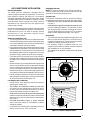
2. Verify blower wheel is spinning in direction indicated by
arrow. Feel the air being circulated by the indoor blower
and verify that it is cooler than ambient temperature.
Listen for any unusual noises. If unusual sounds occur,
determine the source of the noise and correct as
necessary.
3. Verify HI and LO refrigerant pressures.
4. Allow the system to operate for several minutes and then
set the temperature selector above room temperature.
Verify the fan and compressor cycle off with the
thermostat. NOTE: The blower should also stop unless
fan mode is set to the ON position.
System Heating (optional)
1. Set the thermostat's system mode to HEAT and the
temperature mode above room temperature.
2. Verify the optional heating equipment (furnace or
electric heat) and indoor blower energize. Feel the air
being circulated by the indoor blower and verify that
it is warmer than ambient temperature. Listen for any
unusual noises. If unusual sounds occur, determine the
source of the noise and correct as necessary.
Refrigerant Charging
WARNING:
S4QD Split System Air Conditioners are shipped
fully charged with R410A refrigerant and ready
for installation. When system is installed
according to these instructions, no refrigerant
charging is required. If repairs make it necessary
for evacuation and charging, it should only
be attempted by qualified trained personnel
thoroughly familiar with this equipment. Under
no circumstances should the owner attempt to
install and/or service this equipment. Failure to
comply with this warning could result in property
damage, personal injury, or death.
After refrigerant line connections are completed, it is
required that you leak check and evacuate the indoor
section and all line connections (using proper methods)
before finalizing the full system refrigerant charge.
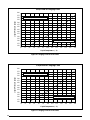
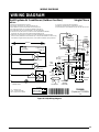
• Refrigerant charging charts are applicable only to
matched assemblies of NORDYNE equipment and
listed airows for the indoor coil. Refer to Figures 2 - 7
(pages 10 - 12) for correct system charging.
• S4QDoutdoorunitswithnon-AHRIlistedindoorcoils
are not recommended. Deviations from rated airflows or
non-listed combinations may require modification to the
expansion device and refrigerant charging procedures
for proper and efficient system operation.
• Therefrigerantchargecanbecheckedandadjusted
through the service ports provided external to the
outdoor unit. Use only gage line sets which have a
“Schrader” depression device present to actuate the
valve.
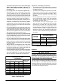
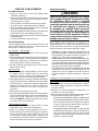
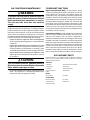
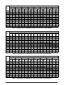
Charging an R-410A system in AC mode at outdoor
temperatures above 55° F for optimized sub-cooling of
10° F - 12° F.
1. With the system operating at steady-state, measure
the liquid refrigerant pressure (in psig) at the outdoor
unit service valve.
2. Measure the liquid refrigerant temperature (in
Fahrenheit) at the service valve.
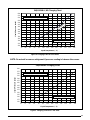
3. Determine the required liquid refrigerant pressure from
the appropriate charging chart (Figures 3 - 8).
•IfthepressuremeasuredinStep1isgreaterthan
the required liquid refrigerant pressure determined in
Step 3, then there is too much charge in the system.
Remove refrigerant and repeat Steps 1 through 3
until the system is correctly charged.
•IfthepressuremeasuredinStep1islessthanthe
required liquid refrigerant pressure determined in
Step 3, there is too little charge in the system. Add
refrigerant and repeat Steps 1 through 3 until the
system is correctly charged.
7
COMPONENT FUNCTIONS
High Pressure Switch (HPS) - A high-pressure switch
is factory-installed and located in the liquid line internal
to the outdoor unit. The switch is designed to protect the
system when very high pressures occur during abnormal
conditions. Under normal conditions, the switch is closed.
If the liquid pressure rises above 575 psig, then the switch
will open and de-energize the outdoor unit. The switch will
close again once the liquid pressure decreases to 460
psig. Please note that the switch interrupts the thermostat
inputs to the unit. Thus, when the switch opens and then
closes, there may be a 5 minute short cycling delay before
the outdoor unit will energize.
Low-Pressure Switch - (Select Models) A low-pressure
switch is factory-installed and located in the suction line
internal to the outdoor unit. The switch is designed to
protect the compressor from a loss of charge. Under normal
conditions, the switch is closed. If the suction pressure falls
below 5 psig, then the switch will open and de-energize the
outdoor unit. The switch will close again once the suction
pressure increases above 20 psig. Please note that the
switch interrupts the thermostat inputs to the unit. When
the switch opens and then closes, there will be a 5 minute
short cycling delay before the outdoor unit will energize.
AIR CONDITIONER MAINTENANCE
WARNING:
To prevent electrical shock, personal injury, or
death, disconnect all electrical power to the unit
before performing any maintenance or service.
The unit may have more than one electrical
supply.
Proper maintenance is important to achieve optimum
performance from the air conditioner. The ability to properly
perform maintenance on this equipment requires certain
mechanical skills and tools. If you do not possess these
skills, contact your dealer for maintenance. Consult your
local dealer about the availability of maintenance contracts.
Routine maintenance should include the following:
• Inspectandcleanorreplaceairltersatthebeginning
of each heating and cooling season, or more frequently
if required.
• Inspectthecondensatedrainandoutdoorcoilatthe
beginning of each cooling season. Remove any debris.
Clean the outdoor coil and louvers as necessary using
a mild detergent and water. Rinse thoroughly with water.
• Inspecttheelectricalconnectionsfortightnessatthe
beginning of each heating and cooling season. Service
as necessary.
CAUTION:
The unit should never be operated without a
filter in the return air system. Replace disposable
filters with the same type and size.
• Donotaddadditionaloiltomotorsunequippedwithoil
tubes. The compressor is hermetically sealed at the
factory and does not require lubrication.
REPLACEMENT PARTS
Replacement parts are available through all Nordyne
distributors.
Please have the complete model and serial number of the unit when
ordering replacement parts.
Electrical
Capacitors Temperature Limit Switches
Compressors Thermostats
Contactors Time Delay Relays
Pressure Switches Transformers
Relays
Motors
Blower Motor Fan Motor
Components
Blower Assembly Fan Grille
Cabinet Panels Filter/Driers
Expansion Valves
8
Suct.
Press.
OUTDOOR TEMPERATURE (° F)
70 75 80 85 90 95 100 105
Liq.
Press.
Dis.
Temp.
Liq.
Press.
Dis.
Temp.
Liq.
Press.
Dis.
Temp.
Liq.
Press.
Dis.
Temp.
Liq.
Press.
Dis.
Temp.
Liq.
Press.
Dis.
Temp.
Liq.
Press.
Dis.
Temp.
Liq.
Press.
Dis.
Temp.
126 257 136
128 258 139 280 139
130 259 143 281 143 304 143
132 266 146 282 146 305 146 327 146
134 270 150 288 150 306 149 328 149 351 150
136 291 153 310 153 329 153 352 153 374 153
138 313 156 332 156 353 156
375 156
397 157
140 335 160 355 160 376 160 399 160 421 160
142 337 163 357 163
378 163
400 163 422 163
144 359 166 380 166 401 166 423 167
146 381 170 402 170 424 170
148 404 173 425 173
150 426 176
152
Table 4. Charging Table for S4QD-024KC Series (2 Ton Units) - Orifice Matches
APPLICATION NOTES FOR USING S4QD REFRIGERANT
CHARGING CHARTS & TABLES - COOLING ONLY
NOTES:
1. All pressures are listed psig and all temperatures in °F
2. Discharge temperatures GREATER than charted values
indicate an UNDERCHARGED system.
3. Discharge temperatures LESS than charted values
indicate an OVERCHARGED system.
• This equipment’s cooling system contains refrigerant under high pressure. Always use safe and
environmentally sound methods when handling refrigerant handling or servicing the unit. Review the
factory literature and safety warnings prior to servicing.
• Whenrepairingsystemleaks,alwaysuseanitrogen(inert)gastoprotecttherefrigerantsystemandpressure
check the repair before re-charging. Always replace the filter-dryers when performing any repair to the refrigeration
system with one capable of acid removal. After completing the repairs, evacuate the system to 350 - 500 microns
and weigh in the refrigerant to the amount specified on the unit rating label.
• Therefrigerantchargingchartsandtablesarevalidforavarietyofindoor,returnairconditionsandaremost
influenced by the outdoor ambient temperature, outdoor fan operation and the unit operating voltage. Before using
these tables and charts, make sure the unit is in a stable operating mode. As shown in Tables 4 - 7 (pages 8 & 9)
and Figures 2 - 7 (pages 10 - 12), the ideal system sub-cooling can vary over the range of operation. Reference
the tables to determine the ideal amount of sub-cooling for a given liquid pressure. Units charged to other values
will not perform at the rated unit efficiency (EER) or rated Coefficient of Performance (COP) in heating mode.
• Toinspectasystemsoperationusingqualityinstruments,matchthemeasuredliquidtemperaturetotheunits
table. The measured liquid pressure reading should be within 3% of the table value for most installations.
• Forsystemsthatareoperatingwithmorethana5%deviation,inspecttheunitforthepropervoltageandphase
balance and the refrigeration system for leaks.
• Unitsthatareoperatingatlessthen95%ofthenominalvoltageorwitha2%phaseimbalancemayseeamore
significant deviation than the amount stated above.
• DO NOT use the tables in systems that have a fan cycling under low-ambient control. Refer to the low-ambient
kit instructions for more information. (If applicable)
LEGEND
Shaded boxes indicate flooded conditions.
Rated design values. The suction pressure
will be lower than design value if outdoor air
flow, entering dry bulb, or entering wet bulb
temperatures are lower than design.
9
Suct.
Press.
OUTDOOR TEMPERATURE (° F)
70 75 80 85 90 95 100 105
Liq.
Press.
Dis.
Temp.
Liq.
Press.
Dis.
Temp.
Liq.
Press.
Dis.
Temp.
Liq.
Press.
Dis.
Temp.
Liq.
Press.
Dis.
Temp.
Liq.
Press.
Dis.
Temp.
Liq.
Press.
Dis.
Temp.
Liq.
Press.
Dis.
Temp.
127 259 142
129 260 145 283 145
131 261 149 284 148 307 148
133 262 152 285 152 308 151 331 150
135 263 155 286 155 309 154 332 154 355 153
137 287 158 310 157 333 157 356 157 379 156
139 311 161 334 160 357 160
380 160
403 159
141 335 164 358 163 381 163 404 163 427 162
143 336 167 359 166
382 166
405 166 428 166
145 360 170 383 169 406 169 429 169
147 385 173 407 172 430 172
149 409 175 432 175
151 433 178
153
Table 5. Charging Table for S4QD-030KC Series (2 .5 Ton Units) - Orifice Matches
Suct.
Press.
OUTDOOR TEMPERATURE (° F)
70 75 80 85 90 95 100 105
Liq.
Press.
Dis.
Temp.
Liq.
Press.
Dis.
Temp.
Liq.
Press.
Dis.
Temp.
Liq.
Press.
Dis.
Temp.
Liq.
Press.
Dis.
Temp.
Liq.
Press.
Dis.
Temp.
Liq.
Press.
Dis.
Temp.
Liq.
Press.
Dis.
Temp.
131
266 143
133 267 147 291 146
135 269 150 292 149 316 148
137 270 154 294 152 317 152 341 151
139 272 158 295 156 319 155 342 154 366 154
141 297 160 320 159 344 157 367 157 391 156
143 322 162 345 161 369 160
392 159
416 159
145 347 164 370 163 394 163 418 162 441 161
147 348 168 372 166
395 166
419 165 443 164
149 373 170 397 169 420 168 444 168
151 398 172 422 171 445 171
153 423 174 447 174
155 448 177
157
Table 6. Charging Table for S4QD-036KC Series (3 Ton Units) - Orifice Matches
Suct.
Press.
OUTDOOR TEMPERATURE (° F)
70 75 80 85 90 95 100 105
Liq.
Press.
Dis.
Temp.
Liq.
Press.
Dis.
Temp.
Liq.
Press.
Dis.
Temp.
Liq.
Press.
Dis.
Temp.
Liq.
Press.
Dis.
Temp.
Liq.
Press.
Dis.
Temp.
Liq.
Press.
Dis.
Temp.
Liq.
Press.
Dis.
Temp.
130 257 130
132 259 133 282 134
134 260 136 283 137 306 137
136 262 138 284 140 307 141 330 141
138 264 140 286 142 308 144 331 145 354 145
140 288 144 310 146 332 148 355 148 378 149
142 311 148 333 150 356 152
379 152
402 153
144 335 153 357 154 380 156 403 156 426 157
146 337 155 359 157
381 158
404 159 427 160
148 360 159 382 161 405 162 428 163
150 383 164 406 165 428 166
152 407 168 429 169
154 430 172
156
Table 7. Charging Table for S4QD-042KC Series (3.5 Ton Units) - Orifice Matches
10
250
275
300
325
350
375
400
425
450
475
500
525
550
575
600
75 80 85 90 95 100 105 110 115 120 125 130 135
Liquid Pressure (psig)
S4QD-030KA / KB Charging Chart
Liquid Temperature ( ° F)
Add refrigerant when below curve
Remove refrigerant when above curve
SEE NOTE
SEE NOTE
NOTE: Do not add or remove refrigerant if pressure reading is between the curves.
250
275
300
325
350
375
400
425
450
475
500
525
550
575
600
75 80 85 90 95 100 105 110 115 120 125 130 135
Liquid Pressure (psig)
S4QD-024KA/KB Charging Chart
Liquid Temperature ( ° F)
Add refrigerant when below curve
Remove refrigerant when above curve
Figure 2. Charging Chart for 2 Ton Units
Figure 3. Charging Chart for 2.5 Ton Units
11
250
275
300
325
350
375
400
425
450
475
500
525
550
575
600
75 80 85 90 95 100 105 110 115 120 125 130 135
Liquid Pressure (psig)
S4QD-036KA / KB Charging Chart
Liquid Temperature ( ° F)
Remove refrigerant when above curve
Add refrigerant when below curve
Figure 4. Charging Chart for 3 Ton Units
250
275
300
325
350
375
400
425
450
475
500
525
550
575
600
Liquid Pressure (psig)
S4QD-042KA Charging Chart
70 75 80 85 90 95 100 105110 115 120 125 130
Liquid Temperature ( ° F)
Add refrigerant when below curve
Remove refrigerant when above curve
SEE NOTE
NOTE: Do not add or remove refrigerant if pressure reading is between the curves.
Figure 5. Charging Chart for 3.5 Ton Units
12
250
275
300
325
350
375
400
425
450
475
500
525
550
575
600
Liquid Pressure (psig)
S4QD-048KA Charging Chart
70 75 80 85 90 95 100 105 110 115 120 125 130
Liquid Temperature ( ° F)
Remove refrigerant when above curve
Add refrigerant when below curve
Figure 6. Charging Chart for 4 Ton Units
250
275
300
325
350
375
400
425
450
475
500
525
550
575
600
Liquid Pressure (psig)
S4QD-060KA Charging Chart
70 75 80 85 90 95 100 105 110 115 120 125 130
Liquid Temperature ( ° F)
Remove refrigerant when above curve
Add refrigerant when below curve
Figure 7. Charging Chart for 5 Ton Units
13
WIRING DIAGRAMS
Figure 8. S4QD Wiring Diagram
Single Phase
1. Couper le courant avant de faire letretien.
2. Employez uniquement des conducteurs en cuivre.
3. Ne convient pas aux installations de plus de 150 volt a la terre.
710388B
(Replaces 710388A)
0109
WIRING DIAGRAM
Split System Air Conditioner (Outdoor Section)
NOTES:
1. Disconnect all power before servicing.
2. For supply connections use copper conductors only.
3. Not suitable on systems that exceed 150 volts to ground.
4. For replacement wires use conductors suitable for 105 deg C.
5. For ampacities and overcurrent protection, see unit rating plate.
6. Connect to 24 vac/40ca/class 2 circuit. See furnace/airhandler installation
instructions for control circuit and optional relay/transformer kits.
7. Anti-Short Cycle Timer (ASCT) may or may not be installed in the unit. If desired,
ASCT is factory installed on select models only or may be field installed as shown using
manufacturer’s approved kit. If not present, connect Yellow and Black wires per Note 6.
FIELD WIRING
LEGEND:
LOW VOLTAGE
HIGH VOLTAGE
¢710388B¤
CC - Contactor Coil
CCH - Crankcase Heater
HPS - High Pressure Switch
208/230V
CC
ASCT
ASCT
(SEE NOTE 7)
H
C
F
CCH
(OPTIONAL)
R
C
S
S
C
R
L2
T2
COMPRESSOR
CONTACTS
L1
T1
COMPRESSOR
OUTDOOR FAN
MOTOR
24 VOLT FIELD
CONNECTIONS
HPS
HPS
T2
T1
T3
ASCT
(SEE
NOTE 7)
GROUNDING
SCREW
L1 L2
GND
T1
T2
L1
L2
OUTDOOR
FAN MOTOR
C
S
DUAL
CAPACITOR
R
3
1
2
START
CAPAC
START
RELAY
BLACK
BLUE
ORANGE
YELLOW
CONTACTOR
YELLOW
BLACK
RED
CRANKCASE
HEATER
(OPTIONAL)
YELLOW
BLACK
SEE NOTE 6
RED OR
YELLOW
BLACK
RED OR
RED BLACK
BLACK OR
BLK WHT
C
S
R
YELLOW
OR
YELLOW
BLACK
RED OR
RED BLACK
H
C
F
14
15
INSTALLATION / PERFORMANCE CHECK LIST
Specifications & illustrations subject to change without notice or incurring obligations.
O’ Fallon, MO | Printed in U.S.A. (11/11) 7093210 (Replaces 7089970)
ELECTRICAL SYSTEM:
Electrical connections tight? YES NO
Line voltage polarity correct? YES NO
Rated Voltage: ___________________________________ VOLTS
L1-L2 Volts: _____________________________________VOLTS
L1-L3 Volts: _____________________________________ VOLTS
L2-L3 Volts: _____________________________________ VOLTS
Avg. Volts: ______________________________________ VOLTS
Max. deviation of voltage
from avg. volts: ___________________________________ VOLTS
% Volt imbalance: ________________________________ VOLTS
Blower Motor HP: ________ Sheave Setting ___________# Turns
Has the thermostat been calibrated? YES NO
Is the thermostat level? YES NO
Is the heat anticipator setting correct?
(If Applicable)
YES NO
INSTALLATION ADDRESS:
CITY ________________________ STATE ________________
UNIT MODEL # ________________________________________
UNIT SERIAL # _______________________________________
Unit Installed Minimum clearances per
Figure 1 (page 3)?
YES NO
INSTALLER NAME:
CITY _______________________ STATE ________________
REFRIGERATION SYSTEM:
Was unit given 24 hr warm up period
for crankcase heaters?
YES NO
Stage-1 Liquid Pressure (high side) ________________________
Stage-1 Suction Pressure (low side) ________________________
Has the owner’s information been
reviewed with the customer?
YES NO
Has the Literature Package been left
with the unit?
YES NO
  • Page 1 1
  • Page 2 2
  • Page 3 3
  • Page 4 4
  • Page 5 5
  • Page 6 6
  • Page 7 7
  • Page 8 8
  • Page 9 9
  • Page 10 10
  • Page 11 11
  • Page 12 12
  • Page 13 13
  • Page 14 14
  • Page 15 15
  • Page 16 16

Unbranded DS4(B,Q)D-KB/KC Installation guide

Category
Split-system air conditioners
Type
Installation guide

The Unbranded DS4(B,Q)D-KB/KC is a split system air conditioner designed for manufactured housing, offering efficient cooling and heating solutions. With its 13 SEER rating, it ensures energy savings while maintaining a comfortable indoor environment. It comes in various tonnage options, including 2, 2.5, 3, 3.5, 4, and 5 tons, allowing you to choose the right capacity for your space.

Ask a question and I''ll find the answer in the document

Finding information in a document is now easier with AI