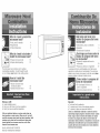
KitchenAid KHMS147HBT2 Installation guide
- Type
- Installation guide

What do t need to install the
microwave hood?
oTools,parts & materials 4
oRequirements 5
oProduct dimensions 5
What do i need to do before i
install the microwave hood?
oPrepare microwave hood 10
, Preparecabinet opening 12
The microwave hood is factory set for ventless
(recircuiating) operation. Tovent through the wail
or roof, changes must madeto the venting system.
How de I install the
microwave hood?
o Secure microwave hood
to waftand cabinet
o Connectmicrowavehood
16
18
Doing se wHm:
7' makeinstallation easier.
7" hetpyou in the future if you havequestions.
7' help if you havean electrical inspection.
Call your authorized dealer or service center when you
havequestions or need service. Whenyea call, Veowill
need the microwave hood model and serial numbers. Beth
numbers can be found on the model/serial rating plate
located behind the microwave oven door on the front
frame of the microwave oven.
Part No. 4619=655=95773/8183731
Parte No=4619=655=95773/8183731
Qu_ tengo que hacerpara
instaiar/a campana dei homo
microondas?
o Instrumentos, piezasy matefiales 4
o Requisites 5
o DimensionesdeI producto 5
o PrepararIacampana del homo de
microondas 10
, Prepararia abertura en eIgabinete 12
La campanadel horno est_ disefiadaper Iaf_brica para
operaci6nsin salida de aire (recircuiaciOn).Para que haya
saiida deaire a trav6s de una pared o del cieio raso, deben
hacersecambios ai sistema de saiida de aire=
_CCmo instaio la ca_._ana dei
orno de microondas.
o Fijeia campanadeI homo a ia
paredo ai gabinete 16
o Conectela campana del homo 18
Haeerle:
7 hark m_s fAcii ia instalaciOn=
7' Io ayudar_en ei future si tiene alguna pregunta=
7' Io ayudar_si tiene una inspeccione!Cctrica=
Uame a sa distribaidor aatofizado o centre de servicio
caando tonga algana preganta o neeesite servicio. Caando
liame, tonga a mane el n_mero del modelo y el n_mero
de sefie de la campana de salida de aire del homo de
microondas. Ambos n_meros se enoaentran en la plata de
clasificacion de modelo,iserie que se encaentra detrds de
la puerta del homode microondas en el marco delantero
dei homo2 de microondas.

C
mm
mm
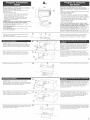
Your safety and the safety of others
are very important.
We haveprovided many important safety messagesin this
manualand on your appiiance=Always read and obey all
safety messages.
This is the safety atert symbol=
This symbol alerts you to potential hazardsthat
can kiii or hurt you and others.
Aii safety messageswit foiiow tile safety aiert symboi and
eitherthe word "DANGER"or "WARNING".Thesewords
mean:
Youcanbe killed or seriously injuredif you don't follow
instructions.
AiI safety messageswill teiI you what the potential hazard
is, teli you how to reducethe chance of injury,and teil you
what canhappen if the instructions are not foflowed=
Su seguridad y ia seguridad de los dem;_s
es muyimpertante.
Hemos inciuido muchos mensajesimportantes de
seguridaden este manualyen su eiectrodom6stico=
Leay obedezcasiempretodos ios mensajesdeseguridad=
Esteese! simbolo de advertenciade seguridad=
Estesimboio ie iiama ia atenciOnsobre peligros
potentiaIes que pueden ocasionar ia muerte
o una iesiOna usted y a ios demAs=
Todosios mensajesde seguridad iron a continuaciOndel
simbolo de advertenciade seguridad
y de ia paiabra"PELiGRO" o "ADVERTENCIA'LEstas
significan:
Si no sigue las instrucciones,usted puede
merit o suffir una lesidn grave.
Todosios mensajesde seguridad ie dir_n ei peligro
potenciai, ie dir_n cOmoreducir ias posibiiidades de
sufrir una iesiOny Io que puedesuceder si no sesiguen
las instrucoiones.
7 observe all governing codes and ordinances.
7' instali microwave hood asspecified in these instructions
or asspecified on waftand upper cabinet templates. It is
recommendedthat a qualified technician install this
microwave hood.
7' haveeverything you needto properly install microwave
hood.
7' checkthe microwavehood for damage. If any damageis
evident, Do Not operatethe microwave oven until it is
checkedby an authorized servicetechnician.
7' placea portion of carton or other heavy material between
tile microwave hood and the floor, countertop or range
top=Do not usea piastic cover=
7" removeshipping materialsand parts from insidetile
microwave oven. Locatetemplates and set them asideto
be used later=
7' determine which venting method you wili use.
7' makesure the microwave hood wiii be mounted against
and supported by both a flat, vertical wall and upper
7' cumptir con todos Ios cOdigosy reglamentosvigentes.
7' instaiar ia campana dei homo como se especificaen estas
instrucciones o en ias piantiiias de ia pared o ei gabinete
superior=Se recomienda que un t6cnico calificado instale la
campanadei homo.
7" tenor todo io quenecesitaparainstatardebidamenteia
campana=
7' verificar si Iacampana est_ da¢iada=Si hayalgOnda¢io,NO
useel homo de microondas hasta que Io revise un t6cnico
de servicio autorizado.
7' colocar un trozo de carton o cuatquier otto material pesado
entre ia campanadel homo y etpiso, ia encimera o ia parte
superior de la cocina=No use unacubierta de pi_stico=
7' quitar ios materiatesy piezasde envio que est_n dentro del
homo de microondas. Locaticeias piantiiias y ap_rteias
para usarlas posteriormente.
7" determinar e! metodo de salida de aire que va a usar.
7' AsegOresedeque la campanadel homo demicroondas
2
cabinet or other horizontai structure.
7' Support for weight of 150 pounds, which inciudes
microwave hood combination and items piacedin the
ovenand upper cabinet.
7' makesure the microwave hood wiii beattachedwith two
lag screws to a minimum of one,vertical 2"x 4" wail
stud.
7' makesure not to mount the microwave hood to an island
or peninsulacabinet.
quede instaladay apoyadaen una pared vertical
pianayen un gabinetesuperior o cuatquier otra estructura
horizontal
7' AsegOresedeque ia estructura deapoyosuperior y ia
trasera para ia campana dei homo de microondassean
capacesde resistir 150 iibras, mAsel peso de ios articuios
que secoiocan dentro de! homo o dei gabinetesuperior.
7' AsegOresedefijar iacampanadelhomo de microondas
con dos torniiios con cabezacuadradapara madera
(torniiios de entibaciOn)a un minimo de un montante de
pared verticai de 2"x 4"=
7' AsegOresedeno instatar Iacampana dethomo de
microondas en un gabineteaislado o peninsular (sin
respaldo de pared).
continued on page4 continElaen la pdgina 4 3

continuedfrompage3
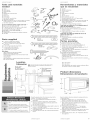
Tools and materials
A. Gloves
B. Safetyglasses
C. Measuringtape
D. Pencii
E. Maskingtape or thumb tacks
F. Scissors
G. Eiectricdrift
H. 3/16" drill bit
L 3/8" and3/4" wood driii bits
J. Fiat-biadescrewdriver
K. Phiiiips screwdrivers: No. 2 for powersuppiy cord clamp
screw and No. 3 for 1/4-20 x 3" round headbolts.
L. Stud finder (optional)
To out 2" diameter power supply cord hole --
NL Keyhoie saw for wood cabinet or,
N. 2"diameter hoiedriii bit for wood or metalcabinet
O. 7/16" nut driver for 1/4" x 2" iagscrews
To cut wail or reef vent opening --
Ni. Keyhole saw
P. Caulking gun and weatherproof caulking compound
Q. Ducttape
Parts supplied
R. 2, 1/4-20 x 3" boits and2washers
(secure microwave hood to cabinet)
S. 4, 1/4-20 x 3" boits and 4 spring toggle-heads
(for drywall)
T. 4, 1/4"x 2"lag screws (for wood studs)
U. I power supply cord clamp and
1 mounting screw (dark colored)
V. 1 power supply cord bushing
Not shown:
Uppercabinet and wali paper templates
Waft/roof vent damper assembiy
Mounting plate (attachedto back of microwave hood)
aluminum fiiters
charcoal fiiters
Note:Dependingon model, aluminum filter and charcoal
filter may be combined.
@
@ Full size
Tamale real
Q Full size
Tamafiereal
iene deia pOgina3
Hettamientas y matetiales
que se neeesitan
A. Guantes
B. Anteojos protectores
C. Cinta de medir
D. L_piz
E. Cintaadhesiva o tachuetas
F. Tijeras
G. TaladroeiOctrico
H. Broca de barrena de3/16"
L Brocas de barrena de 3/8" y 3/4" para madera
J. Destorniiiador de puntapiana
K. Destomiiiadores Phiiiips: No. 2 para prensa detomiiio de
cablede aiimentaciOny No.3 parapemos de cabeza
redonda de 1/4-20 x 3".
L Localizador de pemo prisionero (opcionai)
Para hater un orificio de 2" de di_metro para ei
cable de aiimeotaci@ --
M. Sierra de caiar para gabinetede maderao,
N. Broca de barrenade 2"dedi_metro paragabinete de
maderao met_tico
O. Uave de tuerca de 7/16" paratornillos con cabeza
cuadradapara madera
Para hater un orificio de saiida de aire eo ia
pared o ei cieio raso --
_1.Sierra de caiar
E Pistoia para calafateoy masiiia paracaiafatear
impermeable
Q. Cintaadhesive para conductos
Partes previstas
R. 2 pemos de 1/4-20 x 3"y 2 arandelas
(para fijar Iacampana dethomo aIgabinete)
$. 4 pemos de 1/4-20 x 3"y 4 tuercasacodilIadasde
resorte (para muros interiores sin mortero)
T. 4 torniiios con cabezacuadradapara maderade 1/4"x 2"
(para montantes de pared)
U. 1 abrazaderapara cable deaiimentaciOny un tomiflo de
sujeciOn(color oscuro)
V. I manguito parael cablede alimentaciOn
No aparecen enlas Hustracienes:
Piantiiias de gabinetesuperior y de pared
Conjunto de Iacompuerta dot orificio de salidade aire en
la pared/eicieio raso
Placade montaje (fijada a la partetrasera de [a campana
det homo)
4
@
Eo
@m @m
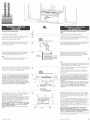
30" rain, cabinet
opening width.
38", anchc minime de la __
abertura del gabinete
T
to fleer
a[piso
NOTE:There must be at least one wall stud within cabinet opening.
NOTA:debe haber al menos un montante de pareddentro de [a
abertura del gabinete,
wall studs
_'lcntantes
de pared
12" to 14" recommended
cabinet deptb
12" a 14% profundidad del
gabinete recomendada
(rl
1 -
Ld I
J I
I I -
filtros de aluminio
fiitros de carbon
Nota: dependiendodel modeio, puedencombinarse fiRros
de aluminio y filtros decarbon vegetal.
Product dimensions
Dimensienes dei preduete
16=1/4"
15=3/8"
66" rain.from floor to top of wall mounting
i
plate.
66" minimo des@ el piso hasta ia parte
superior de Iaplaca de montaje en Ia pared.
30"rain, to cookingsurface(or countertop)
belowmicrowavehood.
30"minimodes@ lasuperficieparacocinar
(o encimera)debajode Iacampanadel homo.
Checkthe opening wherethe microwave hood wiii be
instaiied. Theiocation must provide:
7' 2" X 4"wood studding and3/8"thickness drywali or
plastedlath.
7 Support for weight of 150 pounds, which inciudes
microwave hood combination and items ptacedin the
ovenand upper cabinet.
7' 30"wide minimum opening.
7" 12"to 14"recommendeduppercabinetdepth to aiiow for
removai or servicing if needed.
7' Protectionfrom draft areas,such as windows, doors and
strong heating vents.
7' Grounded eJectdcaloutlet. See "Electrical Requirements,"
page6.
Reviseia abertura don@se instalar_lacampanadothomo.
El lugar debe tenor:
7' Montantede maderade 2" x 4"y muro interior sin
mortero o yeso/iistOnde maderade 3/8" deespesor.
7' Soporte para e!peso de ia campana deIhomo de 150
[ibras, mAsei peso de ios artlculos que se colocan dentro
deIhomo o gabinetesuperior.
7' Abertura minima de 30" deancho.
7' Profundidad recomendadade 12"a 14"deigabinete
superior para permitir sacar ia campana o reparariao
dadeservicio si fuera necesario.
7' Protecci6ncontra _reascon corrientes de aire, taies come
ventanas,puertas y conductos de ventilaciOnde aire
caiiente.
7' Tomacorrientepuesto a tierra. Ver "Requisites El@trices"
en [ap_gina 6.
continued on page6 continE_aen lapdgina 6

Electrical Shock Hazard
Plug into a grounded 3=prong outlet.
Do not remove ground prong.
Do not use an adapter.
Do not use an extension cord.
Failure to follow these instructions can result
in death, fire, or electrical shock.
important:Observeall governing codesand ordinances.
it isthe customer's responsibility:
Tocontact a qualified emectHcalinstaller.
Toassure that the electrical installationis adequate and
in conformance with National BectficamCode, ANSt/NFPA
70 -- mateetedition*, and all local codes and ordinances.
Yea mast have:
V' 120=volt,60Hz,AC=only,15=or 20=amp.,fused
eiectdcai suppiy.
/ outlet iocated in the upper cabinet asclose as
possible to the microwave hood=
We recommend:
7' a time=delayfuse or circuit breaker=
V_ a separatecircuit serving this appliance only=
Jfcodespermit and a separate groand wire is aaed, it is
recommended that a qualified electriciandetermine that
the groand pathis adeqaate.
Peligro de cheque eJ_ctrico
Enchufelo en un tomacorriente de pared de
conexien a tierra con 3 terminales.
No quite el terminal pare conexien a tierra.
No use adaptador.
No use cable de extensien.
No seguir estas instrucciones puede ocasionar
la muerte, un incendio o un cheque el_ctrico.
Jmportante: campla con redes los cedigoa y reglamentoa
vigentes.
Eareapenaahilidad dei cliente:
Uamar a un t_cnice ee inatamacieneaem_ctricaacamificade
para hater la iestalacihn.
Aaegararae de qae la inetalaci6nel_ctricasea cerrecta y
adecuada y de acuerde con eI C_digo National de Energ[a
ANStiNFPA70= _ltima edicien*, y redes los cedigoa y
reglamentoa locales.
Uated debe tenor:
_/Un suministro electrico, protegido per fusibie, de 120
voitios, 60 Hertz,s0Io de CA, de 15 0 20 ampedos=
7' Untomacorfiente de pared ubicado en e!gabinete
superior io m_scoma posibIe de ia campanadel homo=
Recomendamos:
/ Unfusible de retardo o un disyuntor=
7' Uncimuito separados01opara esteaparato
electrodomestico=
Si los cediges Io permiteey se usa an cahte de puesta a
tierra separate, se recemienda que un electficiata
calificade determine ai eJtrayecte de la paeata a tierra ea
adecuado.
6
Recommendedground method
Foryour personatsafety,this appiiancemust begrounded.
This appiianceis equippedwith a power suppiy cord having
a 3=prongground piug. Tominimize possibie shock hazard,
the cord must be piugged into a mating 3=prongground°
type waft outlet, grounded in accordancewith the National
EtectdcaICode,ANSi/NFPA70 -- latestedition*, and all
local codes and ordinances=
Copies ofthe standards listed may be obtained from:
* National Fire Protection Association
Batterymareh Park
Qaincy, _'laeeaehaeet_e02269
Metodorecemendadeparela puesta
a tietta
Parasu segufidad personai esteartefacto debeset puesto a
tierra=Esteartefacto est&equipado con un cabIede
aIimentacien provisto de un enchufe de puesta a tierra detres
terminales=Parareducir ai minimo e! fiesgo de cheque
electdco, el came debeset enchufado en un tomacordente de
pared dei mismo tipo con tres terminaIes, puesto a tierra de
acuerdocon el C0digo Nacionalde EnergiaANSi/NFPA70 --
0ltima ediciOn*,y todos Ios cedigos y regiamentos locales=
Copia de los normas indicadas se pueden obtener eli:
* National Fire Protection Association
Batterymarch Park
Qainey, _laeeachaeette 0226g
The microwave hoodisset for ventless(recircalating)
installation. Forwall or roof venting changes to the
venting system must he made.
Salida de aire
Eatacampana demhome ha side diae_ada para set inetalada
sin aalida de aire (recircalaci6n). Para salida de aire en la
paredo en el cieie raao, dehen haceraecamMea en eJ
aistema de salida de aire.
CAUTION: To reduce risk of fire and to
properly exhaust air, be sure to vent air
outside. Do not vent exhaust air into
spaces within walls or ceilings or into
attics, crawl spaces or garages.
PRECAUCIeN: pare reducir el riesgo de
incendio y pare instalar el sistema de
sa_ida de aire adecuado, asegQrese de
que e_ aire sa_ga al exterior. No ponga _a
salida de aire en espacios dentro de
paredes o cie_o rose o en &ticos, setanos
de pequeha a_tura o garajes.
continued on page8 continua en iapdgina 8 7

continued from page 7
For wall or roof ventingmethods:
Choosebetween roof venting or waii venting.
If the waftexhaust method is chosen, be surethat there is
proper clearancewithin the wall for the exhaustvent.
Vent materials needed for installation are not included.
Wall and roof caps must have back-draft damper.
We recommend:
V using rigid metal vent,
7 that length of vent and number of elbows should be
kept to a minimum to provide efficient performance,
¢' that size of vent should be uniform,
¢' using duct tape to seal all joints in the vent system,
V using caulking compound to seal exterior wall or roof
opening around cap,
¢' two elbows should not be installed together,
We do NOTrecommend:
V" flexible metal vent,
NOTE:If fiexibie metai vent must be used,caicuiateeach
foot of fiexibte metal vent astwo feet of rigid metatvent.
Flexible metalelbows count twice as much asstandard
elbows.
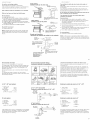
Reef venting
Saiida de a_re par ei cieie rose
roof cap
eapetoza de cielo rose
3=1/4"x 10" throogll=the-rool
a trav6s del cialo rose per an auricle
de 34/4" x 10
Wall venting
Salida de aire par la pared wallcap
caperaz,Jde pared
3=1/4"x 10" through=the=wall
a tray,s de la pared per an
ofificio de 3=1/4"x 10
Rennd vent transition
Transici6n de candncta de saiida de aire redanda
roof cap
caperoza de -_
cielo rose
3" minimum height {required
for damper to fully open)
Altera minima de 3"
{necesaria para qua la
cnmpaerta se abra
completamente}
\
3=1/4"x 10""to 6" round vent
transition
transici6e de conducte de salida
de aire redondo de 3=1/4"x10"
a6"
vienedeia pdgina 7
Para m_tedos de salida de aire a travds de la pared e el
ciele rose:
Decidaentre instaIar la saiida de aire a trav6s dotcieio rasoo
de una pared.
Si se decideper et m6todo de salidade aim a trav6s de ia
pared,asegOresede qua hayae! espacio adecuadodentro de
la paredpara etconducto de salida de aire.
No se iecluyen los matefiales del cenducte de salida de aire
qua se necesitan para la instalaci6n.
Los caperuzas para ciete rose y pared deben tenor
cempaerta de centratire.
Recomefldamos:
7' usar un conducto de salidade aim met_ticoy rigido.
7' que ia iongitud de!conducto de saiida deaire y ei nOmero
de codes se mantengana un minima para Iograr un
rendimiento eficiente.
7' que Ias dimensionesdeIconducto seanuniformes.
7' usarcinta para conducto paraseiiar todas ias unionesen el
sistema de saiida de aim.
7' usar masiiia para caiafatearpara seiiar ia paredexterior o la
aberturaen e!cielo raso alrededor de Iacaperuza.
7' no se debeninstalar dos codes juntos.
No reeomefldamos:
7' conducto de salida deaire met_Iico flexible
NOTA:si debe usarse un conducto met_iicofiexibie, caicule
cadapie de conducto met_iico flexibie come si fueran dos pies
de conducto met_Iico rigido. Los codes de metal flexible hacen
per dos codes est_ndar.
8
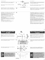
Recommended ventlength:
Use 3=1/4"X 10"rectangularor 6" round vent.
Thetotai iength of the vent system inciuding straight vent,
elbow, transitions, waftor roof caps must not exceedthe
equivalent of 140 feet of 3ol/4" X 10"rectangularor 6"
diameter round vent.
For best performance, useno more than three 90 degree
elbows.
Tocaiculatethe length of systemyou need,add the
equivalentfeet for eachvent piece usedin the system. See
the following examples:
3-1/4"x 10" ventsystem:
1 =3=1/4"x 10"
90°eibow = 25 fL
I =waftcap =40 ft.
8 feet straight = 8 ft.
Length of
3-1/4" x 10"system = 73 ft.
5" vent system:
I - transition = 5 ft.
2 - 90° elbows = 20 ft.
I - waftcap =40 ft.
8 feet straight = 8 ft.
Length of 6" system = 73 ft.
If the existing vent is round, a rectangularoto-roundadapter
must be usedand a rectangular 3"extension ventbetween
the damper assemblyand adaptermust be installed to
prevent damper from sticking.
Recommended standard fittings
Accesarias estdndar recamendadas
3-1/4"x 10"to6"=5ft.
De3-1/4"x 10"a6"=
5 pies
3-1/4"x 10"roofcap=24ft,
Caperuzadecielorasode
3-1/4"x10"= 24pies
3-1/4"x16"waltca
90_elbow:10 ft. =40fL
Codede90:_= Capemzadepared
10pies de3d/4"x 10"=
40pies
3-1/4"x 10"
90 elbow=25ft,
Codede90 y 3-1/4"x
10"=25pies
iiiiiii iili!'
::::::::::i:7iiiiiiiiiiii........ eiiiiiiiiiil;!ii}_
3-1/4"x 10"flat
elbow: 10ft.
%do pianode3-1/4"
10": 10pies
3-1/4"x 10" vent system
Sistema de salida de aire de 3-1/4" x 10"
3=1/4"x 10"
00° elbow
Cede de 00° 7 6 ft.
3=1/4"x 10" _ 6 pies _______e_I
wall cap
caperoza de
pared
6" ventsystem
Sistema de saiida de aire de 6"
00° elbows
code de 90°
6 ft.
/
6 pies
/
T
2 ft. (2 pies}
Lengitud recomendada dot cenducte de salida de aire:
Use un conducto de safidade aim rectanguiar de 3=1/4"x 10"
o redondo de 6".
La Iongitud totai dei sistema de salidade aim, inctuyendo ei
conducto desaiida de aire recto,ei code, iastransiciones, las
caperuzasde paredo cielo raso no debenexceder e!
equivaientea 140 pies de conducto rectangular de salidade
aire de 3-I/4" x 10"o conducto redondo de 6" de di_metro=
Para mejoms resultados, no use mAsde tins codes de 90°.
Paracaicuiar ia iongitud deIsistema qua necesita,agregue ia
equivaienciaen pie paracada pedazode conducto usadoen et
sistema.Yea los siguientes ejemplos:
Sistema de saiida de aire de 3-1/4"x 10":
1 =Codede90°
y 3=1/4"x 10" =25 pies
1 =Caperuzade pared =40 pies
8 pies recto = 8 pies
Longitud de un
sistema de 3=1/4"x 10" = 73 pies
Sistema de saiida de aire de 5"
I =transici6n = 5 pies
2 =codesde90° = 20 pies
I =caperuzade pared = 40 pies
8 pies recto = 8 pies
Longitud de un
sistema de 6" = 73 pies
Si ei actual conducto de salida de aim es redondo,debe usarse
un adaptador de rectanguiar a redondoy un conducto de
extensi6n rectangular de 3"entre elconjunto de ia compuerta
y se debeinstatar el adaptador pareevitar qua la compuerta se
atasque.
traosition
transid6n 9

Remove tape and save for future use,
Remove contentsfrom inside microwave oven including
turn tahb, turn table sappert and huh.
Mounting plateis gray metal plateattachedto back of
microwave hood,
Removethe mounting piate:
o Removetwo screws @ from top of microwave hood
locatedclosest to the front corners. Donot remove
screws located towards the center of hood,
o Removefront griiie ®. Set screws and griiie aside,
o Puffhook ® to releasemounting plate. Separate
i
Qaite la cinta y gu_rdela para uso enel futuro,
Saquetodo Io queest_ dentro del homode microondas
incluyendoel plato giratorio, el soporte del platogiratorio y et
eje.
La phca de montajeesia piacamet_Iicagris queest_en la parte
trasera de IacampanadeIhomo.
Quiteiapiacade montaje:
o Quiteios dostomiiios @ deia partesuperior deia campana
dei homo, queest@ m_sprOximosaias esquinasdetanteras.
rio quiteios tomiiios colocadoshaciaei centro de iacampana.
o QuiteIarejilIadetantera®. AparteIos tornilIosy IarejilIa.
mounting plate and set aside.
o Replacegrill.
Compbteh] close door and replace tape so that door does
not swing open while microwave is being handled,
For ventless(recirculafing) operation, go to "Prepare
cabinet opening" page 12.
Toventthrough the wall, go to step 2 thento step 3, "Wall-
venting installation".
Toventthrough the roof, go to step 2 then to step 6,
"Roof-venting installation".
, Jab el gancho® parasoltar la piacade montaje.Quitela
ptacade montajey ap_rtela.
o Vuetvaa colocarIa rejilIa.
Cierre la puortacompletamentey vuelvaa colecarla cinta
para que la puerta nose ahra mientras se trahaja en el homo,
Parafuncionamiento sin salida de airo (recirculaciCn), vayaa
la secci6n"PrepareiaaberturadeIgabinete"en iap_gina12.
Para sacar emaire a tray,s de la pared,vayaat paso2, Iuegoal
paso3, "instalaci@ con saiidade airea travCsde ia pared".
Parasacar el aire a tray,s del cieio raso, vayaat paso2,Iuego
aIpaso6, "lnstalaciOnconsalidade airea travesdelcielo raso'.
Remove5 screws that attach damperpiate® to top of
microwave hood cabinet.
Keepdamper plateand screws together and set aside.
I I
I
Quiteios 5 torniiios quefijan ia placa de ia compuerta @ a
la partesuperior de!gabinetede Iacampana deIhomo.
Mantengajuntos la compuerta y lostornillos y ap_rtelos.
Carefully slide the air deflector ® out of the cabinet.
Rotateair defiector so that deflector vanes ®wili face out
the rear of the cabinet and the small exhaust port @ of the
air deflectorfacesthe exhaustport ® in microwave hood.
Slide air deflector back into cabinet as far as it wilI go.
Checkthat deflectorvanes ® face the rear ofthe cabinet
and that the small exhaustports @ ® faceeach other.
m
Deslicecon cuidado el deflector de aire ® para sacarlo deI
gabinete. GireeI deflector de aire de maneraque Ias aietasdet
deflector ® quedenorientadas haciaia partetrasera del
gabinetey IaIumbrera de escapepequefia@ deI deflector de
aire quede orientadahacb IaIumbrera de escape® de la
campanadeI homo.
Deslicecompietamenteei deflector de aire paravoiver a
coiocarlo en etgabinete. Verifique que Insabtas deI deflector
® queden orbntadas haciaIaparte trasera detgabinetey que
las Iumbreras de escapepequefias@ @ quedenodentadas la
una hacia [aotra.
10
Reattachdamper plate ® with five screws.
m
@
Vuelvaafijar la ptacade la compuerta ® con cincotorniflos.
........... i
Carefully slide the air deflector ® out of the cabinet.
Rotateair deflector so that deflector vanes® facethe top of
the cabinet and the smaii exhaustport @ of the air deflector
facesthe exhaust port in microwave hood ®.
@
Deslbe con cuidado el deflector de aire ® para sacarlo dei
gabinete. Gireei deflector de aire de maneraque ias aietasdel
deflector ® queden orientadashacia ia partesuperior deI
gabinetey ia iumbrera de escapepequefia@ dotdeflector de
aire quede orientadahacia la lumbrera de escapede la
campanadel homo ®.
Siide air deflector back into cabinet as far as it wiii go.
Checkthat deflector vanes ® face the top of the cabinet and
that the small exhaust ports @ @ face eachother.
DesiicecompletamenteeI deflector de aire para voiver a
coiocario en ei gabinete. Verifique que iasatetasdel deflector
® queden orientadas haciaia parte superior dei gabinetey
que Ias Iumbreras de escapepequef]as@ ® queden
orbntadas la unahacia la otra,
Reattachdamper plate@ with four screws at eachcorner of
the damper piate. Savebright-coiored tapping screw for use
later to attach damper assembly.
m @
Vuelvaa fijar ia piacade ia compuerta @ con cuatro torniiios
en cadaesquina de ia placa de Iacompuerta. Guardeettorniiio
de roscado de colores brilIantespara usado, posteriormente,
para fijar e[conjunto de la compuerta.
11

C
© ,©
mm ml
0
Disconnect powersupply to outlet.
lm
Desooneoteel suministro el_otrico del tomacorriente de
pared.
Put on gioves and safety glasses= 2o POngaseIos guantesy Ios anteojos protectores=
Disconnectand move freestanding rangeto provide easier 3. Desconectey muevaia cocina autoestabieparatener f_cil
accessor put a protective cover over a cooktop= accesoo ponga una cubierta protectora en la encimera=Saque
Removeall contents from upper cabinet, todos ios objetos dei gabinetesuperior=
Using measuringtape, find and ctearIymarkthe verticat
centeriine ® of the cabinet opening on the wall direcey
under the upper cabinet=
m
Con unacinta de medir, iocaticey marque con claridad ia linen
central verticai @ deIaabertura deIgabineteenla pared
directamente debajo dei gabinetesuperior.
Line up paper waii template centerline with centerline on
wali=Tapeor tack watl tempiate to waft=Top of template
must be located a minimum of 66" from floor.
Note:
o If front edge of cabinet is iower than back edge,adjust
top of wall template to be levelwith front edge.
m
rear wall--
pared trasera
J
Tapof wall template must align with
front edge of cabieet.
La parts superior de la piantHia de
pared debe a_ieearse con el bards
delantero del gabinete.
Alinee IaIineacentral de Iaplantiiia de paredcon IaIinea
central de ia pared. Fijecon cinta o clave contachueias ia
ptantiiia de pareda ia pared. La partesuperior de la ptantilla
debe quedara un minima de 66" desdeetpiso.
12
Nora:
oSi el bards delanterode!gabineteestAmAs bajo que et bards
posterior, ajuste ia parts superior de ia piantilla de pared para
que quede niveiadacon ei bards deiantero=
Findand mark the location of alI waii studs on wafttemplate=
If there are no waft studs in the opening area, DONOTinstall
microwave hood. Consult your building inspector.
m
Locaiicey marque Ia ubicaci6n de todos los montantes de
pared en ia piantiiia de pared=
Si no hay montantes de pareden el _rea de Iaabertura, NO
instaie ia campanadel homo=Consults con su inspector de
construcci6n=
Piacethe Uppercabinet template against the bottom of the
upper cabinet. The "rear wall" arrows must be against the
rear wall so that the homescutin the cannot bottom and
the holes in the top of the microwave cabinet will align.
1
ColoqueIapiantiila de pared dei gabinetesuperior contra ia
basedei gabinetesuperior. Lasfleohas de la "Pared Trasera"
deben estar contra la pared trasera de manera que los
orificioshechos en Jabase del gabinete y losorificies en la
If the cabinet bottom has a frame around it, trim the
template edgesso that the template fits inside the frame
againstthe cabinet bottom. Thetempiate hastrim iinesto
useas guides, important: The t8-7/16" dimension from the
rear wall to holes "J" and 'I(" must be maintained.
0
wall template
Plantilla de pared
parts superior del gabinete del homo microondas queden
alineados.
Si ia basedel gabinetetiene un marco, carte ios bordes de ia
plantiiia para que ia piantiiia encajedentro dot marco,contra ia
basedetgabinete. La piantiiia tiene linens de carte que deben
usarse coma guias, tmportante: se debe mantener la
distanoia de 18o7/16"de Japared trasera a Josorificios
"J" y "K".
Checkif points "D" and"E", or "F" and "G"on walitemptateare
overa waftstud ®: if pointsareovera waftstud,drill 3/16"
hoies=if pointsareoverdrywall,driii 3/4"holes.
If thereisnota watistud at points"D" and "E", or"F" and"G"
or at onlyoneset of points,find within shadedareas"H" and"I"
thescrew pointsclosestto thecenterofwaftstud(s). Driii3,/16"
holes® into wailstud(s).Twoor preferablyfour lagscrews
mustbe usedto securemountingpintoto waii.
Note:the mountingpmatetViUSTbe scouredtothe wall atthe
fourcorner points "[1" and "E", or "F" and "G", usingeither
1/4o28x3"bolts and toggleheadsor 1/4 x 2"Jagscrews.
(Referto Section Cpage 15.)
Thelocation of your wall stud(s) may differ from what is
shown,
m
Verifique que ios puntos "D" y "E', o "F" y "G" deiapiantiiia
de pared est6n sabre un montante de pared®: siios puntos
est_n sabre un montantede pared,haga orificios de 3/16"=Si
los puntos est_n sabre un muro interior sin mortero, haga
orificios de 3/4".
Si no hay ning_n montante de pared en ios puntos "D" y "E",
o "F" y "G", o s6Io en un par de puntos, iocaiice dentro de Ins
_reassombreadas"H" e "I" los puntos para torniiios m_s
cercanosal centro dei montante oios montantes de pared=
Hagaorificios de 3/16" ® en ei montanteo en ios montantes
de pared. Debenusarsedos o, preferiblemente,cuatro
tornilIos de cabezacuadrada para maderaparafijar la placade
montaje de pared=
Nora: ia placa de montaje DEBEfijarse a la pared en los
puntos de ins coatro esquinas "g" y "E" o "F" _'"G",
usando ya sea pernos de cabeza redonda o acodillada de
t/4-28 x 3" o tornillos con cabezacuadrada para madera de
1/4 x 2" (Consults la Seaside Cen map_gina t5).
Sus montantes de pared podrian edar en lugaresdiferentes de
los que se muestranen la ilustracien=
continued onpage I4 continElaen ia pdgina t4 :1.3

continued from page t3
Use a hole drill or key hole saw to cut a 2"diameterholeat
shadedarea marked "M" on upper cabinet template.
m
Note: Instaii a power supply cord bushing around hole if
cabinet is metal.
Drill 3/8" holes at points "J" and "K" on upper cabinet
template. Theseare for 2, 1/4-20 x 3" round head bolts and
washersusedto secure microwavehoodto upper cabinet.
10.
metal cabinet f
gabinete met_,_i
iene deia p4gina I3
Use una broca de barrena o unasierra de catarpara hacerun
orificio de 2"de di_metro en ei _reasombreada marcada"M"
en la plantilla del gabinetesuperior.
Nota: Instaie un manguito aislador del cabie de alimentaci6n
alrededor det odficio si el gabinetees de metal.
Hagaorificios de 3/8" en ios puntos "J" y "K" deia piantiiia dei
gabinetesuperior. Estosorificios son para 2 pernos de cabeza
redonda de 1/4-20 x 3"y Iasarandelasse usanpara fijar la
campanadel homo aJgabinetesuperior.
For ventbss, removetemplates and go to "Attach mounting
ptateto wali" page15. Keepdamperassembtyfor use if
microwave hood is everventedthrough waiI or roof.
tf veeringthrough the reef, driii 3/4" hob in one corner of
shadedrectangular area marked "L" on upper cabinet
template. Use key hole saw and cut outthe shaded
rectanguiar area. Removeboth templates.
Do Not instaii vent at this time. 6o to "Attach mounting
plateto wali," page 15.
tf ventingthrough the wall, driiI 3/4" hob in one corner of
shadedrectanguIararea marked "r/" on wali tempIate. Use
key hob saw and cut out rectangulararea. Removeboth
templates.
Instali vent through vent opening in waii.
Use caulking to seai waftopening around exhaustcap.
6o to "Attach mounting plateto wall," page15.
Para iestalaci6e sic salida de aire, quite ias piantiiias y vaya
a "file Ia piacade montaje a Iapared" en Iap_gina 15.6uarde
ei conjunto de ia compuerta para usarla si ia campana dei
homo iiega a instaiarsecon salidade aim atray@ delapared
o dei cie!o raso.
Si se iestala la salida de aire a trav6s det ¢iele rase, haga
un orificio de 3/4" enunaesquina del_rearectanguiar
sombreada marcada"L" en ia piantiiia de!gabinetesuperior.
Use una sierra de calary corte ei _rea rectanguiarsombreada.
Quiteias dos piantiiias.
No instale ei conducto de saiida deairetodavJa.Vayaa ia
secci6n "file ia piacade montaje a ia pared"en ia p@ina 15.
Si se iestala la salida de aire a trav6s de la pared, haga un
orificio de 3/4" en unaesquina dei _rea rectangular sombreada
marcada"N" en ia piantiiia de pared. Use unasierra caladay
corte ei _rea rectangular.Quiteias dos piantiiias.
JnstaleeJconducto de salidade aim a trav@ de Jaaberturaen
la pared.
Use masiiia de caiafatearpara seliar ia aberturaen ia pared
airededor de ia caperuzade saiida de aire. Vayaa ia secciOn
"File Japlaca de montaje a Japared", enJapAgina15.
£4
Insert 1/4-20 x 3"toggle bolts @ through holes in mounting
plate® that matchthe iocation ofthe 3/4" hobs in the
drywall.
Start a spring toggle nut ® on the end of eachtoggie boit.
Leaveenough space for the toggb to go through wail and
open.
lm Inserte pernos acodiiiados de 1/4-20 x 3" @ a trav6s de ios
orificios en Iaplacade montaje ® que coincidan con Ios
puntos don@ est_n ios orificios 3/4" enei inure interior sin
mortero.
Inserte una tuerca acodilladade resorte © en ei extreme de
cadapemo acodiIIado. Dejeespaciosuficiente para que el
tornillo pasea trav6s de la paredy seabra.
Position mounting piate@ on the waft. Pushtoggle bolts
@ and nuts @ through the drywall ®.
m
Coioqueia piaca de montaje @ enia pared.Empujeios pernos
acodilIados@ y lastuercas © a trav6s del inure interior sin
mortero ®.
Fingertighten thetoggle bolts @ to makesure toggie nuts
© haveopened against drywall ®.
Aprietecon ios @dos Ios pernos acodiiiadas @ para
asegurarsede que iastuercasacodiiiadas de resorte © se
hayanabbrto contra etinure interior sin mortero ®.
m
/
mouetieg plate
plusa dr moetage
£5

Placeawasheroneach1/4o20x3"boltandplaceinside
uppercabinetbythe3/8"hobs.
Ventless er reef venting: Ge te Step 3.
lm
Wall venting installation:
Checkthat damperblade @ is ontop of tab ®,moves
freely,and opensfully. The damper must open fully. Push
damper assembiy© througll openingin mounting plate®
so that tabs in damper assembiy iock damperassembly
against mounting plate. Long tab ® of damper assembly
must beto left.
m
Coloqueuna arandetaen cada perno de 1/4=20x 3"y coJ6quela
dentro detgabinetesuperior cerca de los odficios
de 3/8".
Para instalaci6nsin aalida de aire e consalida a tray,s del
ciele raao: vayaal Paso3.
tnstalacidn consalida a tray,s de la pared:
Verifique que Iahoja de Iacompuerta @ est6sobre IaIeng0eta
® y sepueda mover Iibremente=Empujeel conjunto de Ia
compuerta © a trav6s de Iaaberturaen Iaplacade montaje @
para que Ias bng0etas en e! conjunto de Iacompuerta fijen el
conjunto de Ia compuertacontra Ia placade montaje=La
bngOetaIarga® detconjunto de la compuerta debe quedara
la izquierda.
Excessive Weight Hazard
Use two or more people to move and install
microwave hood.
Failure to do so can result in back or other
injury.
Make surethe ovendoor is completely closed and taped
shut.
Carefuliyiift microwave hood and hang it on support
tabs ® at the bottom of mounting plate.
m
Peligro de peso excesivo
Dos o mas personas deben trasladar e instalar la
campana del homo de microondas.
No seguir esta instrucci6n puede ocasionar
lesi6n en la espalda u otto tipo de lesi6n.
AsegOresede que Ia puertadel homo est6completamente
cerraday fijada con cintas.
Levantecon cuidado ia campana de!homo y cu6iguela de las
bngOetas desoporte ® en la parteinferior de la placade
montaje.
Rotatefront of microwave cabinetdownward. Threadpower
suppiy cord through the power supply cord hole in the
bottom of the upper cabinet.
m
Gire Iaparte delanteradeIgabinetedeI homo haciaabajo. Pase
e!cable de alimentaciOnper el orificio para ei cable de
alimentaci@ en la basedet gabinetesuperior.
Rotatemicrowave hood up towards cabinet. Push
microwave hood against mounting plate untii iocking
latch @ snaps into microwave hood.
NOTE:This wiii support the microwave hood untii the
two 1/4=20x 3" bolts inside the upper cabinet are installed.
m
Gire Iacampana deIhomo haciaarriba en direcci6n deI
gabinete. Empujeia campanadei homo contra ia piaca de
montaje hasta que el pestillo asegurador@ encajeen et
gabinete.
NOTA:Esto servir&de apoyo a ia campanadei homo hasta que
se instaien los dos pernos de 1/4o20x 3" dentro del gabinete
superior.
16
m
/
17

Wallventingor re¢irculatingventing:Go to step 2.
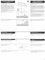
Reef=ventinginstallation:The damper MUSTfully open.
Checkthat damper blade @ is on top of tab ® and moves
freely. Note:if possible,fit the damper assembly and vent
connector or transition piecetogether to check that the
damper opensfuliy before making final vent connection.
Insert damperassembly through cabinet opening ® so that
long tab @ slides under the raisededge of damper piate.
Attachshort tab to damperpiate with bright tapping screw
not usedto attachdamper piate.
Align damper/vent connector with damperassembly on top
of microwave hood and attach. Install vent through vent
opening in upper cabinet.
Use caulking compound to seal roof opening around
exhaustcap.
lm
®
SaJidade aire a tray,s de Japaredosin samidade aire
(recircula¢iCn): vayaal Paso2.
JnstaiaeiCnconsalida de aire a tray,s del ebb race: La
compuerta DEBEabrirsecompbtamente. Verifique que ia
hoja de Iacompuerta @ est6 sobre IaIengOeta® y se pueda
mover iibremente. Nota:Si fuera posibb, unaei conjunto de
la compuertay etconector detconducto desalida de aire o ia
pbza de traesbiOn para verificar si ia compuerta se abre
compbtamente antes de haceria conexiOnfinal dei conducto
desalida de aire.
Insertee! conjunto de lacompuerta atravCsdeiaabertura
del gabinete© de maneraque Ia IengOetaIarga@ se deslice
debajodeI borde Ievantadode Iaplaca de Iacompuerta. Fije
la be@eta corta a ia piaca de ia compuerta con ettorniilo de
roscado brillante que no se us6 para fijar la placa dela
compuerta.
Alinee ia compuerta/e! conector deIconducto de saiida de
aire con el conjunto de Iacompuerta sobre Iacampana det
homo y fijeta. Instaleel conducto de salida de aire a travCsde
la abertura desatida de aire dei gabinetesuperior.
Use masilIade calafatearpara seJlarla abertura en el cielo
rasoatrededor de la caperuzade salidade aire.
Coil power supply cord througll clamp ®. Secureclamp to
cabinet side wall with darkcolored screw.
EnrolIeet cabiede aiimentaciOnen Iaabrazadera®. Fijela
abrazaderaa la pared lateraldel gabinetecon el tornillo
oscuro.
18
Referto Owner's Manualor Useand CareGuidefor
instructions to assemblecharcoalfilters into your model.
Consulteen el Manuaidei Propietarioo Ia Guiade Usey
Cuidadoiasinstrucciones para instalar los filtros de carbon
en su modelo.
Referto Owner's Manualor Useand CareGuidefor
instructions to assemblefilters intoyour model.
Consulteen el Manualdel Propietarioo Ia Guiade Usey
Cuidadolasinstrucciones para instalar los filtros en su
modelo.
Plug power cord into grounded outlet.
Reconnectpower supply.
m
EnchufeeIcable de alimentaciOnen et tomacorriente puesto a
tierra. Vuelnaa conector el suministrode energia.
Readthe Owner'sManual or Useand CareGuide,then
checkthe operation of microwave hood.
m
Leael Manualdet Propietario o IaGuiade Usey Cuidado,
luego verifique el funcionambnto de la campana de salida de
aire dethomo de microondas.
19

oCheckthatttlecircuitbreakerisnottrippedorthehouse
fusebtown.
oCheckthatthepowersupplycordispluggedintothewall
outlet.
oSeetheOwner'sManualorUseandCareGuidefor
troubleshootingchecklist.
oVerifiquequenosehayabotadoeiinterruptorde
circuitooquenosehayafund!dounfusible.
oVerifiquequee!cabiedeaimentaci6nest6enchufodo
eneltomacorrientedepared.
oConsuiteiaseccicabledeatimentacinterruptorde
circuitooquenosehayafund!dounfus.
Caliyourauthorizeddealerorservicecenter.Whenyoucarl,
youwiiineedthemicrowavehoodmodeinumberandserial
number.Bothnumberscanbefoundonthemodei/seriaI
ratingpiateiocatedbehindthemicrowaveovendooronthe
frontframeofthemicrowaveoven.
Llameasudistribuidorautorizadoocentrodeservicio.
Cuandoliame,tengaamanoeinOmerodeimodeioyel
nOmerodeseriedeiacampanadesaiidadeairede!
homodemicroondas.AmbosnOmeroseencuentranen
lapiacadeciasificacisnOmerosseencuentraneniap_s
deiapuertadelhomodemicroondasenetmarco
delanterodelhomodemicroondas.
Accessory kits
Filler Panelkit no. 8171336 - White
8171337 -Biack
8171338 - Biscuit
8171339 - StainlessSteei
99403 - Almond
Fiiier panel kits are avaiiabiefrom your dealerto usewhen
instatiing this microwave oven in a 36"- or 42"- wide
opening. Thefiiier panelscome in pairs and eachpanel is 3"
wide.
Seeyour authorized dealeror service center for details.
ollo
Paneies de reileno
i
J
Juego de aeeesorios
Panelde retlenojuego no.
8171336 - Bianco
8171337 - Negro
8171338 - Bizcochode porcelana
8171339 - Acero inoxodable
99403- Atmendra
Puedeobtenerjuegos de panetesde relIenodel
distribuidor de su iocalidad, para usarlos cuando instate
el homo de microondasen una abertura de
36" - 42"deancho. Los panetesde relleno vienenen
paresy cada uno tiene 3"deancho.
Yeaa su distribuidor autorizado o centro de servicios
para obtenerdetalles.
Part No. 4619-655-95773/8183731 Printed in China
Parte No. 4619-655-95773/8183731 Impreso en China
-
 1
1
-
 2
2
-
 3
3
-
 4
4
-
 5
5
-
 6
6
-
 7
7
-
 8
8
-
 9
9
-
 10
10
-
 11
11


KitchenAid KHMS147HBT2 Installation guide
- Type
- Installation guide
Ask a question and I''ll find the answer in the document
Finding information in a document is now easier with AI
in other languages
Related papers
Other documents
-
Whirlpool MH1141XMB0 Installation guide
-
Whirlpool MH6141XKB2 Installation guide
-
 Futuro Futuro WL36VITTORIA Futuro Futuro Electrical Outlet Clearance
-
 Futuro Futuro WL24STREAM-BLUE Electrical Outlet Clearance
-
 Futuro Futuro WL48CAPRI Electrical Outlet Clearance
-
ELICA PRF0007263 Datasheet
-
Kenmore 66561617100 Installation guide
-
Kenmore Elite 66561682100 User manual
-
-
Kenmore 66562612300 Installation guide


