
Instruction Manual
Ultrasonic Sensor Family U500 and
UR18 with IO-Link

en_BA_U500_UR18_Gen2_IO-Link.docx 2/43 Baumer Electric AG
04.04.2019/ Frauenfeld, Switzerland
Instruction Manual for Ultrasonic Sensor Family U500 & UR18
with IO-Link
Content
1 Sensors covered by this manual ................................................................................................ 4
2 IO-Link Introduction ..................................................................................................................... 4
2.1 SIO / Di Mode Mode ....................................................................................................................... 4
2.2 IO-Link Communication Mode ........................................................................................................ 5
2.2.1 Cyclic data ...................................................................................................................................... 5
2.2.2 Acyclic data ..................................................................................................................................... 5
2.3 IO-Link Device Description (IODD)................................................................................................. 5
2.4 Off-Line Parametrization ................................................................................................................. 6
2.5 Adjustable switching sensor (AdSS) .............................................................................................. 6
3 Sensor in the IO-Link Communication Mode ............................................................................. 7
3.1 Signal Path ..................................................................................................................................... 7
3.2 Process Data .................................................................................................................................. 8
3.2.1 Process Data-In .............................................................................................................................. 8
3.2.2 Process Data-Out ........................................................................................................................... 9
4 Parameter .................................................................................................................................... 10
4.1 System Commands ...................................................................................................................... 10
4.2 Measurement Data Channel (MDC) ............................................................................................. 10
4.2.1 Measurement Value Distance ....................................................................................................... 10
4.2.2 Switch Counts ............................................................................................................................... 10
4.2.3 MDC Source ................................................................................................................................. 11
4.2.4 MDC Unit Code............................................................................................................................. 11
4.2.5 MDC Setpoint limit ........................................................................................................................ 11
4.3 Switching Signal Channel (SSC) .................................................................................................. 12
4.3.1 Setpoints SP ................................................................................................................................. 12
4.3.2 SSC Configuration ........................................................................................................................ 14
4.3.3 Timefilter ....................................................................................................................................... 18
4.3.4 Counter / SSC4............................................................................................................................. 22
4.4 Signal Processing ......................................................................................................................... 24
4.4.1 Moving Average Filter ................................................................................................................... 24
4.4.2 Sonic Cone Adjustment ................................................................................................................ 25
4.4.3 Disruption Filter............................................................................................................................. 25
4.5 Quality Parameters ....................................................................................................................... 26
4.6 Temperature Settings ................................................................................................................... 26
4.7 Output Settings ............................................................................................................................. 27
4.7.1 Switching Output........................................................................................................................... 27
4.7.2 Analog Output ............................................................................................................................... 28
4.7.3 Input Mode of Pin 5 ...................................................................................................................... 29
4.8 Local User Interface ..................................................................................................................... 31
4.8.1 Indication LEDs............................................................................................................................. 31
4.8.2 Teach Mode (Local, by wire) ......................................................................................................... 32
4.8.3 qTeach Lock .................................................................................................................................. 33
5 Teach Commands ....................................................................................................................... 33
5.1 Teach Channel Selection & Teach Status..................................................................................... 34
5.2 Static ............................................................................................................................................. 34

en_BA_U500_UR18_Gen2_IO-Link.docx 3/43 Baumer Electric AG
04.04.2019/ Frauenfeld, Switzerland
5.2.1 Single Point / 1-Point Teach ......................................................................................................... 35
5.2.2 Window Teach .............................................................................................................................. 35
5.3 Static Analog out ........................................................................................................................... 36
6 Diagnosis ..................................................................................................................................... 37
6.1 Device Status ................................................................................................................................ 37
6.2 Device Temperature ...................................................................................................................... 37
6.3 Power Supply Voltage .................................................................................................................. 38
6.4 Bootcyles ...................................................................................................................................... 38
6.5 Operation Time ............................................................................................................................. 38
6.6 Histogram ..................................................................................................................................... 39
6.6.1 Device Temperature ...................................................................................................................... 40
6.6.2 Power Supply ................................................................................................................................ 40
6.6.3 Process Value 1: Distance ............................................................................................................ 41
7 Glossar ........................................................................................................................................ 42

en_BA_U500_UR18_Gen2_IO-Link.docx 4/43 Baumer Electric AG
04.04.2019/ Frauenfeld, Switzerland
1 Sensors covered by this manual
These instruction apply to the following sensor versions:
U500.xyz.2-XXX
UR18.xyz.2-XXX
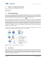
2 IO-Link Introduction
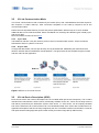
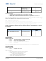
IO-Link is an IO technology standardized worldwide according to IEC 61131-9. It permits manufacturer-
independent digital, bidirectional point-to-point communication. For this purpose, sensors are connected to the
IO-Link master via standardized 3-wire plug-in cables. IO-Link is available for various sensor technologies and
can also be integrated into small miniature sensors. See also here for more information.
With the IO-Link master, which bundles several sensors, the connection to the controller is made via the
respective fieldbus system. In addition, an Ethernet-based connection (with OPC UA) from the master allows
direct communication from the sensor to IT systems. IO-Link masters are available as field devices for
decentralized mounting or as versions for mounting in control cabinets. Many control suppliers also offer IO-
Link input terminals and thus an IO-Link master implemented directly on the control. The maximum cable
length between sensor and master is 20 m. However, significantly longer connections from the sensor to the
controller can be realized by connecting a field master to a field bus system. This gives them maximum
flexibility in the connection solution.
As a member of the IO-Link Consortium, Baumer is involved in developing the standard and is one of the first
manufacturers to feature the new Smart Sensor Profile 1.1. in its sensors.
Figure 1 Example of a system architecture using IO-Link
2.1 SIO / Di Mode
Each port of the IO-Link master can be operated either in SIO mode (standard in-out mode: according to the
latest specification DI mode for sensors and DQ mode for actuators) or in IO-Link mode and thus process the
information of all sensors. In SIO mode, the binary switching output (NPN, PNP or push-pull) of the sensor is
used. In IO-Link mode, the output of the sensor (pin 4) is used as a bidirectional, digital interface to exchange
measurement and diagnostic information.

en_BA_U500_UR18_Gen2_IO-Link.docx 5/43 Baumer Electric AG
04.04.2019/ Frauenfeld, Switzerland
2.2 IO-Link Communication Mode
The IO link communication mode is initiated by the master (PLC) with a standardized command sequence,
this sequence is called “wake-up”. After successful completion of the wake-up sequence the IO link
communication starts.
Data is the most important basis for process and product optimization. With the help of IO-Link, valuable
additional data can be made accessible. Sensor and Master can exchange two different types of data (cyclic
and acyclic data).
More information can also be found here.
2.2.1 Cyclic data
Transmitted in real time. They are used for process control in the automation system. These can also be
transferred to other IT systems via IO-Link.
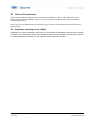
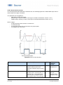
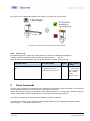
2.2.2 Acyclic data
Through this data stream, sensors (IO devices) can be parameterized. Additionally this data stream also
allows to transmit data for identification and analyzation. The figure below shows the different types of data
and their value for the application.
Figure 2 Different IO Link data streams
2.3 IO-Link Device Description (IODD)
Each IO-Link Device has a device description file, the so-called IODD (IO Device Description). This contains
data about the manufacturer, article number, functionality, software version etc., which can be easily read out
and further processed by the automation system. Each device, i.e. each sensor, can be uniquely identified
both via the IODD and via an internal device ID. The identification data of the sensor also includes device or
application descriptions that can be freely assigned by the user. The IODD consists of several files: a main file
and optional external language files (both in XML format), as well as image files (in PNG format).

en_BA_U500_UR18_Gen2_IO-Link.docx 6/43 Baumer Electric AG
04.04.2019/ Frauenfeld, Switzerland
2.4 Off-Line Parametrization
Off-line sensor parameter adjustment via convenient user interfaces in the PC (via USB Master) or via
Wireless App (via Wireless Master). Sensors can be conveniently configured at the desk and installed
without further teach-in.
Even if IO-Link is not implemented in the machine control, sensors can be operated in SIO mode and use
this advantage
2.5 Adjustable switching sensor (AdSS)
Additionally, the sensors described in this manual can be operated as “adjustable switching sensors (AdSS)”
according to the Smart Sensor Profile. When treated as AdSS the sensors-Master communications happens
via a fully standardized command set. Thus operation without IODD file is possible.

en_BA_U500_UR18_Gen2_IO-Link.docx 7/43 Baumer Electric AG
04.04.2019/ Frauenfeld, Switzerland
3 Sensor in the IO-Link Communication Mode
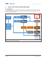
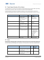
3.1 Signal Path
The signal path describes the rough position of a parameter in the signal processing chain. The path starts
with the measuring value in the top left corner and finishes either with a physical pin (top right) or as output
via the process data (bottom right).
Figure 3 Illustrates the signal path from raw data to an output either through a physical pin (top right) or as
output via the process data (bottom right)
Process Data
Out
Measuring
Value
(Distance)
Signal
Processing
- Filtering
- Disruption
filter
- Sonic Cone
Adjustment
SSC2:
Setpoint
Configuration
SSC1:
Setpoint
Configuration
MDC Source
Output Source
& Configuration
Counter
Source &
Configuration
SSC 1
SSC 2
SSC 4
MDC
Output
Switch
Counter
Module

en_BA_U500_UR18_Gen2_IO-Link.docx 8/43 Baumer Electric AG
04.04.2019/ Frauenfeld, Switzerland
3.2 Process Data
With the sensor in the IO-Link communication mode, process data is cyclically exchanged between the IO-
Link master and the device. Process data is exchanged to and from the sensor (SensorMaster). The
master does not need to explicitly request these process data.
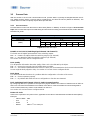
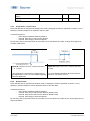
3.2.1 Process Data-In
Process Data-In is sent from the sensor to the master (Sensor Master). As shown in Figure 4 Process data
Input, the Process Data Input is an 48bit string and structured according to the Smart Sensor Profile definition
PDI48.INT32_INT8.
IO-Link Process Data Input
47 16
15 8
7 0
IntegerT(32)
IntegerT (8)
8 bit
Measurement value
(MDC)
Scale
Baumer specific
7
6
5
4
3
2
1
0
SSC4
Alarm
Quality
SSC2
SSC1
Figure 4 Process data Input
Bit 0/Bit 1: SSC1/SSC2 (Switching Signal Channel 1 & Channel 2)
These bits are the digital representation of the switching outputs.
Bit1 = 0 → There is no object within the switching range (Logic: Normal)
Bit1 = 1 → An object lies within the switching range (Logic: Normal)
See section 4.3 to learn how to configure this bit
Bit 2: Quality
This bit provides information about the quality of the sonic echo reflected by the object.
Bit2 = 0 → Sensor has enough signal to reliable detec an object
Bit2 = 1 → The reflection detected from the sensor is critical, it is recommended to check sensor in the machine.
Sensor might be badly aligned or dirty. See section 4.5 to learn how to configure this bit.
Bit 3: Alarm
The alarm bit indicates that there is a problem with the configuration or function of the sensor.
Bit3 = 0 → Sensor operates properly.
Bit3 = 1 → A problem with either the sensor configuration or function was detected.
Bit 5: Switching Signal Channel 4 (SSC4), Switch Counter Function
By configuring SSC4, it is possible to set up a binary signal related to the number of switchcounts of SSC1 or
SSC2. An auto-reset and timefilters are included, to be able to create a full-featured counter being able to
count lot sizes without any need to code software on the PLC.
See section 4.3.4 to learn how to configure this bit.
Bit 8 to 15: Scale
Value is the exponent to the power of ten, applicable to the value of the Measurement Data Channel (MDC)
Example:
- Value of MDC 1000
- Unit m
- Scale -6
- Means 1000*10
-6
m or 1000 m

en_BA_U500_UR18_Gen2_IO-Link.docx 9/43 Baumer Electric AG
04.04.2019/ Frauenfeld, Switzerland
Bit 16 to 47: MDC
MDC stands for measurement data channel. Via this channel the distance value or the switch counts of SSC1,
2 or 4 can be read out as 32 bit integer value. See section 4.2 to learn how to configure the MDC.
3.2.2 Process Data-Out
This data is cyclically sent from the master to the sensor (MasterSensor).
IO-Link Process Data Output
Bit:
7
6
5
4
3
2
1
0
Trigger
Find Me (Localization: LEDs
flashing)
Disable
Transducer
Bit 0: Disable Transducer
By changing this bit the transducer is disabled. This switches off the sensing element without switching off the
electronics. The sensor will not deliver a measurement or switching value. This can be useful to measure
neighbouring sensors sequentially.
Bit 0 = 0 → Transducer is enabled
Bit 0 = 1 → Transducer is disabled
Bit 1: Find Me Function
Signalling e.g. by flashing LEDs (green, yellow, and red) on the sensor to locate and physically identify a
sensor in a machine or system. The signalling can be triggered, for example, from the engineering tool of the
controller.
Bit 1 = 0 → Find Me Function is deactivated
Bit 1 = 1 → Find Me Funktion is activated, LEDs are flashing.
Bit 2: Trigger
Via this Bit it is possible to trigger a single measurement from the sensor. For this Bit to have a function the
DI/DO Settings.Input Mode has to be set to Trigger see 4.7.3.4. This is very useful when many sensors are
mounted next to one another and do influence each other. Using this mode no additional wires are needed in
order to sequentially measure on multiple sensors.
Bit 2 = 0 → Trigger is disabled, the sensor does not measure and the sensor element is deactivated
Bit 2 = 1 → Trigger is enabled, the sensor measures edge-triggered and the sensor element is activated.

en_BA_U500_UR18_Gen2_IO-Link.docx 10/43 Baumer Electric AG
04.04.2019/ Frauenfeld, Switzerland
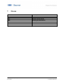
4 Parameter
4.1 System Commands
A factory reset of the sensor activates the default parameters as programmed in the factory. All parameters
changed by the user will be lost. The factory reset can also be triggered via local teach-in (qTeach or wire
teach) directly at the sensor (see assembly instruction for more information) where only the parameters that
are changed via teach-in will be reset.
Parameter name
Short Description
Rights
Unit / Allowed
values
Standard command
Restore Factory Settings
wo
4.2 Measurement Data Channel (MDC)
4.2.1 Measurement Value Distance
Parameter name
Short Description
Rights
Unit / Allowed
values
Measurement Value.
Distance
Process value for distance
ro
mm
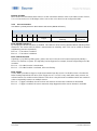
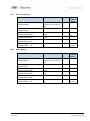
4.2.2 Switch Counts
For each individual SSC a switching counter is implemented, which can be used as diagnosis data or also as
measurement value. The number of counts of each channel can also be mapped to the measurement data
channel MDC by adjusting the MDC source. Trigger of counter is on positive slope of related SSC.
Parameter name
Short Description
Rights
Unit / Allowed
values
- SSC1 Switch Counts
Reset
- SSC2 Switch Counts
Reset
- SSC4 Switch Counts
Reset
Command to set the counter value of
the SSC to zero
wo
- Switch Counts.SSC1
Resetable
- Switch Counts.SSC2
Resetable
- Switch Counts.SSC4
Resetable
Total number of switch counts on
SSC1 (resetable by user command->
SSC1 Switch Counts Reset)
Available for SSC1,2 and 4.
ro
32 Bit value

en_BA_U500_UR18_Gen2_IO-Link.docx 11/43 Baumer Electric AG
04.04.2019/ Frauenfeld, Switzerland
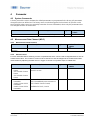
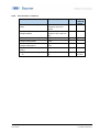
4.2.3 MDC Source
Selects which measuring value is mapped to the MDC channel and is then available via the process data-IN
path. When SSC1, SSC2 or SSC4 is selected the number of switches detected by the channel is shown.
Parameter name
Short Description
Rights
Unit / Allowed values
MDC Selection.Source
Select the process value that is
shown on the MDC channel
ro
- Distance (Default)
- Switch Counter SSC1
- Switch Counter SSC2
- Switch Counter SSC4
4.2.4 MDC Unit Code
Parameter name
Short Description
Rights
Unit / Allowed values
MDC Descriptor.Unit
code
Indicates the unit of the selected
MDC source
ro
4.2.5 MDC Setpoint limit
This parameter allows to read out the limits of the measuring range of the sensor.
Parameter name
Short Description
Rights
Unit / Allowed values
MDC Descriptor.Lower
limit
Lower value of measuring range, if
value is below out of range is
shown
ro
A0: 50 mm
MDC Descriptor.Upper
limit
Upper value of measuring range, if
value is above out of range is
shown
ro
A0: 1500 mm

en_BA_U500_UR18_Gen2_IO-Link.docx 12/43 Baumer Electric AG
04.04.2019/ Frauenfeld, Switzerland
4.3 Switching Signal Channel (SSC)
The sensor features three different switching channels. Switching Signal Channels SSC1 and SSC2 are
reserved for distance measurements, whereas Switching Channel 4 has a counter function with an auto-
reset. All switching channels can be adjusted via IO-Link. All switching channels can be mapped to the MDC
as well. Then they will show the counts detected by the channel.
For more information about how to set-up the Counter/SSC4 channel and its behavior, please see section
4.3.4.
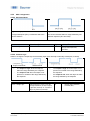
4.3.1 Setpoints SP
Using this parameter the user can modify the switchpoint of the sensor by entering the distance value at
which the sensor should switch (teach-by-value function). For the reflex barrier the parameter
“Reflector.Position” defines the position of the reflector. Figure 5 shows the illustration of the switch point.
For Single point mode only SP1 is relevant, SP2 is not active. For the Window mode SP1 & SP2 are active.
The switching modes are explained in section 4.3.2.1
Figure 5 Single Point Mode
SP1: Switch point 1
SP2: is not active
Figure 6 Window Mode
SP1: Switch point 1
SP2: Switch point 2
Parameter name
Short Description
Rights
Unit / Allowed values
SSC1 Param.SP 1
Set the distance at which the related
SSC is set to active (or inactive if
inverted)
rw
Limits: A0: 50 to
1500mm, Default SP1
1000mm,
SSC1 Param.SP 2
Set the distance at which the related
SSC is set to inactive (or active if
inverted). Only active if SSC is set to
window mode
rw
Limits: A0: 50 to
1500mm, Default SP2
70mm,
The parameters "Reflector.Position" and "Reflector.Tolerance" apply exclusively to the reflection barrier
under the condition that the window switch for SSC1 is activated.
Parameter name
Short Description
Rights
Unit / Allowed
values
SSC1 Param.SP 1
Set the lower limit of the Reflector Position.
The reflector can change the position between
lower and upper limit.
rw
Limits: A0: 50 to
1500mm, Default
SP1 , 950mm,
SSC1 Param.SP 2
Set the upper limit of the Reflector Position.
The reflector can change the position between
lower and upper limit.
rw
Limits: A0: 50 to
1500mm, Default
SP2, 1050mm,
Reflector.Position
Select the reflector position, works together
with the parameter Reflector tolerance.
(SP1=ReflectorPosition*(1-
rw
Limit: 100 to
1250mm
Default 1000 mm

en_BA_U500_UR18_Gen2_IO-Link.docx 13/43 Baumer Electric AG
04.04.2019/ Frauenfeld, Switzerland
ReflectorTolerance;
SP2=ReflectorPosition*(1+ReflectorTolerance)
Reflector.Tolerance
Select the reflector tolerance, works together
with the parameter Reflector position. The
reflector tolerance is selectable between 1
and 20 %. It sets the tolerance window
symmetrically around the reflector position.
The upper and lower tolerance can be read off
at SP1 and SP2.
rw
Limit: 1… 20%
Default: 5%

en_BA_U500_UR18_Gen2_IO-Link.docx 14/43 Baumer Electric AG
04.04.2019/ Frauenfeld, Switzerland
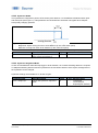
4.3.2 SSC Configuration
4.3.2.1 Switching Mode
Figure 7 Single point
A single switchpoint (SP1) is defined at which the
sensor switches.
Figure 8 Window Mode
The sensor switches within a range defined by two
different setpoints (SP1 and SP2)
Parameter name
Short Description
Rights
Unit / Allowed values
SSC1 Config.Mode
Selects the SSC switch mode
rw
-Disabled
-Single Point (Default)
-Window
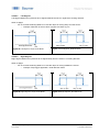
4.3.2.2 Channel Logic
Allows to change the output logic from Normally Open (NO, Normal) to Normally closed (NC, Inverted).
Single Point Mode Window Mode
Single Point Mode Window Mode
Figure 9 «Normal» or NO setting
- The output is high, when the object is
within the range defined by the setpoints.
- The output is low when the object is not
present our outside of the range defined by
the setpoints
Figure 10 «Inverted» or NC setting
- The output is high when the object is not
present our outside of the range defined by
the setpoints
- the output is low, when the object is within
the range defined by the setpoints
Parameter name
Short Description
Rights
Unit / Allowed values
SSC1 Config.Logic
Selects the SSC logic. It can be
changed between "active if object
is present (normal)" or "inactive if
object is present (inverted)"
rw
- Normal (NO) (Default)
- Inverted (NC)

en_BA_U500_UR18_Gen2_IO-Link.docx 15/43 Baumer Electric AG
04.04.2019/ Frauenfeld, Switzerland
4.3.2.3 Hysteresis Width
The hysteresis is configured in percent of the switch point distance. It is the difference between switch point
and reset point (see Figure 11). This parameter can be beneficial to smoothen out signals when samples
have quickly changing positions.
Figure 11 Hysteresis is the difference between switch point and reset point
- Bright blue: object moving from far to close distance (in this case switch point)
- Dark blue: moving from close to far distance (in this case reset point)
Parameter name
Short Description
Rights
Unit / Allowed values
Hysteresis.SSC1 Width
Adjust hysteresis width as percent
of the switch point distance
rw
Limits 0 … 99 %, Default 4%
4.3.2.4 Hysteresis Alignment Mode
In case of axial detection tasks like stop trigger or level detection, an accurate switching distance is required.
To adapt the switching behavior and the hysteresis to the movement direction of the object, the alignment of
the hysteresis can be changed.
Hysteresis settings are available for .P, D and .R types.
Parameter name
Short Description
Rights
Unit / Allowed values
SSC1 Config.Hyst
Selects the hysteresis alignment
mode
rw
- Left Aligned
- Center Aligned
- Right Aligned (Default)

en_BA_U500_UR18_Gen2_IO-Link.docx 16/43 Baumer Electric AG
04.04.2019/ Frauenfeld, Switzerland
4.3.2.4.1 Left Aligned
Left Aligned defines the hysteresis to be aligned towards the sensor / against the sensing direction.
When to apply?
- For an accurate switching distance in case the object is moving away from the sensor
o Example: Detection of the low level of a tank to avoid a dry-run
Figure 12 Left Aligned, Single Point Mode
Figure 13 Left Aligned, Window Mode
4.3.2.4.2 Right Aligned
Right Aligned defines the hysteresis to be aligned away from the sensor / in sensing direction.
When to apply?
- For an accurate switching distance in case the object is moving towards the sensor.
o Example: Stop trigger application, usual detection tasks.
Figure 14 Right Aligned, Single Point Mode
Figure 15 Right Aligned, Window Mode

en_BA_U500_UR18_Gen2_IO-Link.docx 17/43 Baumer Electric AG
04.04.2019/ Frauenfeld, Switzerland
4.3.2.4.3 Center Aligned
A compromise between left and right aligned. The hysteresis is aligned symmetrical around the individual
setpoints.
Figure 16 Center Aligned, Single Point Mode
Figure 17 Center Aligned, Window Mode
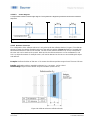
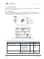
4.3.2.5 Reflector Tolerance
The configuration of the reflector tolerance is only relevant for the reflective barrier (.R types). The reflector
tolerance states the relative allowable variance of the reflector position. Figure 18 shows an example with
two different tolerances that can be selected. The two shown reflector tolerances (A and B) correspond to
the ones who can be teached via q-teach. With IO-Link the reflector tolerance can be set between 1 and
20%. An object that enters for example area A, will not be detected as the sensor cannot distinguish object
and reflector.
Example: Reflector Position of 500 mm ± 5 % means the reflector position ranges from 475 mm to 525 mm.
Benefit: Applications with an unstable background, e.g. conveyors, can be solved.
Disadvantage: Object must be further away from reflector (at least 10 %).
Figure 18: Reflector tolerance reflective barrier

en_BA_U500_UR18_Gen2_IO-Link.docx 18/43 Baumer Electric AG
04.04.2019/ Frauenfeld, Switzerland
Parameter name
Short Description
Rights
Unit / Allowed values
Reflector Tolerance
Set reflector tolerance as
percentage of the sensing range
rw
Limit: 1…20%
Default: 5%
4.3.3 Timefilter
This changes the timing of the switching signals, for example to avoid bouncing/suppress false switching
operation. The ability to directly parametrize and configure the timing on the sensor itself, removes the need
to have additional coding on the PLC or to use pulse stretching adapters.
The described time filters can be configured and applied to each SSC individually.
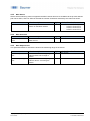
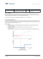
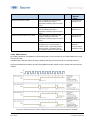
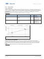
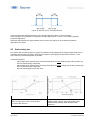
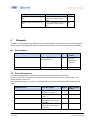
4.3.3.1 Response Delay Time
The response delay time defines the time, the measurement value needs to be above (single point mode) or
inside (window mode) the switchpoints of the related SSC until its status changes to active (or inactive, if the
logic is inverted as described in section 4.3.2.1)
When to apply?
- To avoid the detection of small peaks/false switching operations due to structure changes of the
background or similar.
- To avoid wrong switching of known disturbances such as the wheel of a mixer
- To avoid bouncing.
- To optimize the timing of the execution of a subsequent actor triggered by the output of the sensor.
Figure 19: Response Delay

en_BA_U500_UR18_Gen2_IO-Link.docx 19/43 Baumer Electric AG
04.04.2019/ Frauenfeld, Switzerland
Parameter name
Short Description
Rights
Unit /
Allowed
values
Response Delay.SSC1 Time
Sets / indicates the response delay
time in milliseconds for the
respective switching signal channel
(SSC).
rw
0 to 60.000 ms
Default: 0 ms
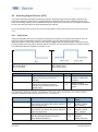
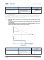
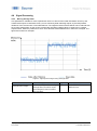
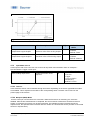
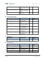
4.3.3.2 Release Delay Time
The release delay time defines the time, where the measurement value needs to be below (single point) or
outside (window mode) of the switchpioints of the related SSC, until its status is changed to inactive (or
active, if the logic is inverted as described in section 4.3.2.1)
When to apply?
- To avoid false switching operations in case of an object which is not 100% stable to detect over the
whole length
- To supress short losses of a proper signal due to known disturbances such as the wheel of a mixer
- To avoid bouncing.
- To optimize the timing of the execution of a subsequent actor triggered by the output of the sensor.
- To detect a unwanted gap size within a continuous flow of products.
Figure 20: Release Delay
Parameter name
Short Description
Rights
Unit /
Allowed
values
Release Delay.SSC1 Time
Sets / indicates the release delay
time in milliseconds for the
respective switching signal channel
(SSC).
rw
0 to 60.000 ms
Default: 0 ms

en_BA_U500_UR18_Gen2_IO-Link.docx 20/43 Baumer Electric AG
04.04.2019/ Frauenfeld, Switzerland
Page is loading ...
Page is loading ...
Page is loading ...
Page is loading ...
Page is loading ...
Page is loading ...
Page is loading ...
Page is loading ...
Page is loading ...
Page is loading ...
Page is loading ...
Page is loading ...
Page is loading ...
Page is loading ...
Page is loading ...
Page is loading ...
Page is loading ...
Page is loading ...
Page is loading ...
Page is loading ...
Page is loading ...
Page is loading ...
Page is loading ...
-
 1
1
-
 2
2
-
 3
3
-
 4
4
-
 5
5
-
 6
6
-
 7
7
-
 8
8
-
 9
9
-
 10
10
-
 11
11
-
 12
12
-
 13
13
-
 14
14
-
 15
15
-
 16
16
-
 17
17
-
 18
18
-
 19
19
-
 20
20
-
 21
21
-
 22
22
-
 23
23
-
 24
24
-
 25
25
-
 26
26
-
 27
27
-
 28
28
-
 29
29
-
 30
30
-
 31
31
-
 32
32
-
 33
33
-
 34
34
-
 35
35
-
 36
36
-
 37
37
-
 38
38
-
 39
39
-
 40
40
-
 41
41
-
 42
42
-
 43
43


Ask a question and I''ll find the answer in the document
Finding information in a document is now easier with AI
Related papers
-
Baumer UR12.P50-GP1C.7BF Operating instructions
-
Baumer U500.PA0.2-GP1J.72F Operating instructions
-
Baumer RR30.DAO0-IGPI.9VF Owner's manual
-
Baumer O200.ER-GW1J.72NV/E026 Operating instructions
-
Baumer IF08.D03L-Q25.GP1I.7VNU Operating instructions
-
Baumer O300.GP-GW1J.72N/E022 Operating instructions
-
-
-
-
Other documents
-
IFM DI5034 Installation guide
-
IFM DI604A Operating instructions
-
-
Leuze RK46C.DXL3/4W-M12P1 Operating instructions
-
red lion MDC User manual
-
Panasonic HG-C1000L Series User manual
-
 Magnescale MF10-P1/P2 Owner's manual
-
Microsonic pms-15/CF/A1 User manual
-
IFM O8H202 Operating instructions
-
CARLO GAVAZZI LD30EPBR60BPM5IO Owner's manual
