Page is loading ...

®
Aeterna Change-Giver
Coin Mechanism rel. 2.7
Maintenance and instructions manual

The information included in this manual may be modified without any prior notice and are not
binding for COGES S.p.A. COGES S.p.A. did all his best to collect and control the information
reported in this manual, but, however, it shall not be responsible for any interpretation of it. This
applies also to any person or company involved in the drawing up and in the production of this
manual. In the event of disputes regarding the interpretation of this document in any case the
version in Italian alone shall prevail.
Unless otherwise stated, any reference to companies, names, data and addresses herein reported is
merely an example and it simply aims to show the use of COGES product.
Any reproduction, in any form, of any part of this manual is forbidden unless previously agreed upon
in writing with COGES S.p.A.
First Edition: April 2009
Second Edition: June 2009
Third Edition: September 2009
Fourth Edition: March 2010
Fifth Edition: April 2010
Sixth Edition: July 2010
Seventh Edition: April 2011
Eighth Edition: October 2011
Ninth Edition: January 2012
Version: 954000/0/09GB/1201 Code: 551052/6

3
TABLE OF CONTENTS
®
Introduction ......................................................................................... pag. 5
Chapter 1................................................................................................. pag. 7
1. Aeterna Change-Giver Coin Mechanism rel. 2.7.......................................... pag. 7
1.1. Composition ................................................................................. pag. 7
1.2. Technical Specifications .................................................................. pag. 8
1.2.1. Specifications of the Coin Mechanism ............................................ pag. 8
1.3. Parts description ........................................................................... pag. 9
1.3.1. Aeterna Change-Giver Coin Mechanism .......................................... pag. 9
1.3.2. Aeterna Coin Mechanism with side cash-box .................................... pag. 10
1.3.3. Label for Coin Mechanism configuration ......................................... pag. 10
1.3.4. Base board ............................................................................ pag. 11
1.3.5. Validator/Separator Group ......................................................... pag. 12
1.3.5.1. Keypad and display ............................................................ pag. 13
1.3.5.2. IR Label.......................................................................... pag. 13
1.3.6. Tube Group ........................................................................... pag. 13
1.3.6.1. Tube box ........................................................................ pag. 14
1.3.6.2. Accumulation tubes ........................................................... pag. 14
1.3.6.3. Elastic forks .................................................................... pag. 14
1.3.7. Ejection Group ....................................................................... pag. 14
1.3.8. Technical data label................................................................. pag. 15
1.4. Accessories available on request ........................................................ pag. 15
1.4.1. Interface for electromechanical Automatic Vending Machine ................ pag. 15
1.4.2. MDB Cashless System ................................................................ pag. 16
1.4.3. MDB Bill Validator.................................................................... pag. 16
1.4.4. Recharge Key ......................................................................... pag. 16
1.4.5. EXE-RS232 Interface for Systems and Change-giver ............................ pag. 16
1.4.6. Accessories for programming and updating...................................... pag. 17
1.4.6.1. Maxi Programmer .............................................................. pag. 17
1.4.6.2. PC programming interface for systems/validators ....................... pag. 17
1.4.7. Accessories for data recording..................................................... pag. 18
1.4.7.1. Integrated IR interface ....................................................... pag. 18
1.4.7.2. Harness for serial communication to PC ................................... pag. 18
1.4.7.3. IR PORT Module ................................................................ pag. 18
1.4.7.4. Comunica Module .............................................................. pag. 18
1.4.7.5. Harness for printer ............................................................ pag. 19
1.5. General Operation ......................................................................... pag. 19
1.5.1. Coin reading .......................................................................... pag. 19
1.5.2. Operation conditions ................................................................ pag. 20
Chapter 2................................................................................................. pag. 21
2. Installation and connections ................................................................. pag. 21
2.1. Installation .................................................................................. pag. 21
2.1.1. Position of the Coin Mechanism ................................................... pag. 21
2.1.2. Fastening holes of the Coin Mechanism .......................................... pag. 21
2.1.3. Installation modes ................................................................... pag. 22
2.1.4. Configuration of the tube box ..................................................... pag. 23
2.1.4.1. Mechanical parts associated with the Euro coins ......................... pag. 24
2.1.5. Checks before starting .............................................................. pag. 24
2.1.6. First loading........................................................................... pag. 25
Table of Contents

4
TABLE OF CONTENTS
®
2.1.7. Tube loading .......................................................................... pag. 25
2.1.7.1. Loading from the tube box ................................................... pag. 25
2.1.7.2. Loading from the coin inlet channel........................................ pag. 25
2.1.7.3. Loading by using the assisted loading function ........................... pag. 26
2.1.7.4. Installing the interface for electromechanical vending machines ..... pag. 26
2.2. Connections ................................................................................. pag. 27
2.2.1. Executive, BDV Coin Mechanisms and electromechanical VM................. pag. 27
2.2.2. MDB Coin Mechanisms ............................................................... pag. 28
2.2.3. Warning................................................................................ pag. 28
Chapter 3................................................................................................. pag. 29
3. Programming .................................................................................... pag. 29
3.1. Programming the Coin Mechanism....................................................... pag. 29
3.1.1. Programming keypad ................................................................ pag. 29
3.1.2. Access to programming ............................................................. pag. 30
3.2. Programming by means of keypad ....................................................... pag. 30
3.2.1. Programming Menu .................................................................. pag. 30
3.3. Recording the data......................................................................... pag. 62
3.3.1. Aeterna Coin Mechanism............................................................ pag. 62
3.3.2. EVA-DTS recording on PC ........................................................... pag. 62
3.3.3. Comunica Module .................................................................... pag. 62
3.3.4. IR PORT Module ...................................................................... pag. 63
3.3.5. Recording by means of printer..................................................... pag. 63
3.4. Firmware update ........................................................................... pag. 64
3.4.1. Firmware update of the Base board by PC....................................... pag. 64
3.4.1.1. Firmware update of the Base board by Maxi Programmer .............. pag. 64
3.4.2. Firmware update of the Validator/Separator group............................ pag. 65
3.4.2.1. Firmware update by PC ....................................................... pag. 65
3.4.2.2. Firmware update by Maxi Programmer..................................... pag. 65
3.4.3. Update of the programmed model ................................................ pag. 65
3.4.3.1. Model update by PC ........................................................... pag. 65
3.4.3.2. Model update by Maxi Programmer ......................................... pag. 66
3.5. Executive communication between PC and Coin Mechanism........................ pag. 66
3.5.1. Management of Executive protocol to PC ........................................ pag. 66
3.5.2. Codes necessary for starting ....................................................... pag. 66
Chapter 4................................................................................................. pag. 67
4. Cleaning and maintenance.................................................................... pag. 67
4.1. Cleaning the Validator/Separator Group ............................................... pag. 67
4.1.1. Cleaning the sliding channel ....................................................... pag. 67
4.1.2. Cleaning the plastic parts .......................................................... pag. 68
4.1.3. Cleaning the photocells and the tube box ....................................... pag. 68
Chapter 5................................................................................................. pag. 69
5. Warnings.......................................................................................... pag. 69
5.1. Aeterna menu rel. 2.7 .................................................................... pag. 71
Appendix ................................................................................................. pag. 73

5
INTRODUCTION
®
Introduction
The main characteristic of the Aeterna Change-Giver is the possibility of giving back any excess
credit present after the sale. This function comes from a system of coin selection and accumulation
inside the tube group. The Change-Giver is prepared to support the following protocols: BDV, MDB,
Executive and Parallel. The Aeterna Coin Mechanism is made almost entirely of plastic materials and
it can be divided into four main units:
• Coin Mechanism Base board;
• Validator/Separator group;
• Tube group;
• Ejection group.
In the Base Board of the Coin Mechanism take place the main microprocessor, the eeprom containing
the programming data and the reference model for the coins, the connectors for connecting to the
peripherals of the payment system, the PC programming interface, the peripherals for data recording
and for the Coin Validator.
The Validator/Separator group can accept up to 60 types of coins or tokens. The coins which result
to be valid are addressed to a conveyor with different channels, each of them is addressed to the
tubes or the cash. On the front panel of the Validator/Separator group is placed the programming
keypad and the display of the Coin Mechanism.
The Tube group is the "store" of the Coin Mechanism where the coins which are used to deliver the
change are accumulated.
The Ejection group consists of 3 motors and 5 cams of different shape; each of them pushes the coin
towards the return channel during the delivery phase.
WARNING: to use your Aeterna Change-Giver Coin Mechanism correctly, it is essential to
follow the instructions given in this manual. We strongly recommend that you read every
part carefully before starting up the System, so as to prevent possible damage due to im-
proper use.

6
INTRODUCTION
®

7
AETERNA CHANGE-GIVER COIN MECHANISM REL. 2.7
®
Chapter
1
1. Aeterna Change-Giver Coin Mechanism
rel. 2.7
The Aeterna Change-Giver Coin Mechanism is available for the BDV, MDB and Standard Executive
protocols. In this latter case it can manage the Parallel operation mode too (for electromechanical
vending machines). All the versions are equipped with an infrared interface integrated in the
Validator/Separator group for data recording.
All the functions of the Coin Mechanism are managed by the Base board, with only one connection
point for programming and PC connection. To make the installation on the vending machines with
limited space easier its dimensions and design were improved. The Coin Mechanism is proposed in
two different versions: with lower cash-box or with side cash-box. It was realized according to the
BDV mechanical specifications for the installation.
1.1. Composition
fig. 1
1 = Connecting harness for vending machine
2 = Harness for MDB peripherals
3 = Label for Coin mechanism configuration
4 = Aeterna Change Giver Coin Mechanism
1
2
3
4

8
CHAPTER 1
®
1.2. Technical Specifications
1.2.1. Specifications of the Coin Mechanism
fig. 2
Dimensions (LxPxH)............................................. mm. 138 x 80 x 382
Weight ........................................................................... 1,7 Kg.
Power supply.................................... 24V AC (Executive) 24V DC (MDB)
Max. absorbed power............................................................. 20 W
Absorbed power at rest ............................................................4 W
Operating temperature ...................................................... 0°/+50°
Acceptance rate................................................2/3 coins per second
No. recognisable coins .............................................................. 60
Max. diameter of accepted coins............................................. 32 mm
Max. diameter of coins addressed to tubes................................. 26 mm
Coin thickness .................................................. from 1 up to 3,2 mm
Max. no. installable tubes ............................................................5
Tube height .....................................................................175 mm
Tube capacity ................................................. from 72 up to 97 coins
Construction material for mechanical parts ....................... Polycarbonate
Price lines:
E.C.S. serial Change-giver coin mechanism...................................... 50
E.C.S. serial C-G Coin M. with power interface and parallel VM ...............5
Protocols used .. BDV Master, MDB Slave level 2 and 3, Executive and Parallel
Directive.............................Electromagnetic compatibility 2004/108/EC
Attention: make sure that the connected power supply keeps at least 30 VA only for the
Aeterna Change-Giver Coin Mechanism
.
Further details concerning the dimensions of the
Coin Mechanism can be found in the drawing in Appendix
369 mm
382 mm
138 mm
8
0
m
m

9
AETERNA CHANGE-GIVER COIN MECHANISM REL. 2.7
®
1.3. Parts description
1.3.1. Aeterna Change-Giver Coin Mechanism
With the Aeterna Executive, BDV Change-Giver Coin Mechanism, for electromechanical vending
machines too, are supplied both a connecting harness to the vending machine and a harness for
MDB peripherals.
fig. 3
1 = Connecting harness to MDB perpherals
2 = Connecting harness to the vending machine
3 = Validator/Separator group
4=Tube group
5 = Ejection group
Attention: the drawings of this manual have only an explanatory purpose and do not allow
any intervention in the Coin Mechanism. On this matter the manufacturer is not responsi-
ble for possible malfunction due to maintenance or repair carried out by unskilled person-
nel.
1
3
4
5
2

10
CHAPTER 1
®
1.3.2. Aeterna Coin Mechanism with side cash-box
It is a Coin Mechanism similar to the standard version as regards the technologies used and the
operation modes of the different modules, but it differs because in this case the slide which con-
veys the coin to the cash-box ends on the Coin Mechanism’s side. This permits to place the box for
coin recovery at the Coin Mechanism’s side, whereas it does not result possible to place the con-
tainer in another position.
fig. 4
1 = Aeterna Coin Mechanism with side cash-box
2 = Slot for coin output with cash destination
3=Box for coin collection
1.3.3. Label for Coin Mechanism configuration
The Change Giver Coin Mechanism is supplied with a configuration label. It shall be sticked on the
vending machine and has two functions: to give instructrions to the user about which coins the
Change-giver can accept and to inform that it can give the change in case any excess credit is
inserted.
1
2
3

11
AETERNA CHANGE-GIVER COIN MECHANISM REL. 2.7
®
1.3.4. Base board
In the Base Board there is the main firmware of the Change-giver Coin Mechanism with all the con-
trol functions on the sales and the credit management, the reference model for the coins and the
management of all the mechanical and electronical functions of the Coin Mechanism.
The firmware update of the Base Board and the model are described in detail at the end of chap-
ter 3 (see para. 3.4. “Firmware update”).
fig. 5
1 = Flat 34-ways connector for Coin Validator (J12)
2 = Minitek 2x5 ways connector for IR PORT Module, PC programming interface for systems/
validators, harness for serial communication to PC and Comunica Module (J4)
3 = Minitek 2x8 ways connector for vending machine (J9)
4 = Minitek 2x9 ways connector for MDB peripherals (J7)
5 = Modu2 8-ways connector for electromechanic interface (J13)
6 = Yellow LED for flash programming (DL1)
7 = Connector for internal use (J5)
8 = Flat 20-ways connector for photocells, coin distribution motors and box presence (J10)
9 = Molex 2-ways connector for coin distribution motor for tube 2(J2)
10 = Molex 2-ways connector for coin distribution motor for tube 3-4 (J3)
11 = White LED for tube lighting (DL3)
12 = Molex 2-ways connector for coin distribution motor for tubes 1-5 (J1)
13 = Green LED for power supply (DL2)
14 = Connector for internal use (J6)
15 = Microprocessor (U8)
16 = Connector for printer (J14)
34
33
2
J12
1
2
1
J7
2
1
J9
J10
20
19
2
1
1
J1
1
1
J3
J14
J4
DL3
81
J13
J5
J2
1
J6
1
2
3
4
5
6
7
8
9
10
11
12
13
14
15
16
DL1
DL2

12
CHAPTER 1
®
1.3.5. Validator/Separator Group
fig. 6
1=Coin inlet
2 = Lever for coin recovery
3=Mobile wall
4 = Keypad and display
5=Conveyor
6 = Tube numbering of Coin Mechanism
7 = Fastening hook to the Coin Mechanism
The Validator/Separator group of the Aeterna Coin Mechanism is characterized by a considerable
speed in coin recognition and their addressing. The new reading systems (optical and magnetic)
permit a higher precision in the coin recognition and therefore a higher reliability in the false
distinction.
The measures read at the coin passage are sent to the Base board of the Coin Mechanism to carry
out the comparison with the model data. When the coin is recognized, that is when the
parameters correspond with those programmed in the model, the Base board communicates to the
Validator/Separator group the coin addressing to the cash, to one of the five tubes or if it should
be rejected.
In the external side of the conveyor is placed the numbering of the tubes just as they are arranged
inside the Coin Mechanism.
The firmware update of the Validator/Separator group is described in detail at the end of chapter
3 (see para. 3.4. “Firmware update”).
1
2
3
4
5
7
6

13
AETERNA CHANGE-GIVER COIN MECHANISM REL. 2.7
®
1.3.5.1. Keypad and display
The keypad and the display of the Coin Mechanism are placed on the lower front side of the
Validator/Separator group. By using the keypad it is possible to set the operation parameters of
the Coin Mechanism and to make its use easier thanks to the display. The latter can give the
operator important information about the operation modes used in the Change-giver at that
moment: Coin mechanism condition, devices enabled, inhibited coins, user profile used during
programming, etc.
All the symbols displayed are explained in detail both in the general operation description (see
para. 1.5.2. “Operation conditions”) and in the programming one. The use of the programming
keys of the Coin Mechanism is fully described in the programming phases explained in chapter 3.
1.3.5.2. IR Label
The IR label, which is placed on the front of the Validator/Separator
group, indicates the presence in the board of the infrared interface
for transmitting the accounting data to a palmtop PC (see
para. 3.3.1. “Aeterna Coin Mechanism”).
fig. 7
1.3.6. Tube Group
The Tube group of the Aeterna Coin Mechanism consists of a box with 5 accumulating coin tubes
and of elastic forks which differ according to the thickness of the coins present in the tubes.
The Tube group, in transparent plastic, is lit from above by 2 white LED’s which permit an
immediate check of the tubes’ content by the operator. The LEDs are lit up when the Coin
Mechanism is switched on and the lighting is automatically switched off after a preset period of
inactivity. The transparent plastic, furthermore, permits a more accurate reading of the tube
filling level on the photocells’ side and make the cleaning operations of the coin mechanism
easier.
fig. 8
1 = Control holes for coin level
2 = Hooking for tube box
3=Tube box
4=Fork
5 = Push-button for box opening
6 = Opening handle
7=Tube 1
8=Tube 2
9=Tube 3
10 = Tube 4
11 = Tube 5
12 = Reject channel
Caution: if you intend to modify the tube configuration with respect to the standard set-
tings, it is necessary to pay great attention to the table present in chapter 2 (see
para. 2.1.4.1. “Mechanical parts associated with the Euro coins”).
3
2
1
4
6
5
7
8
9
10
11
12
2

14
CHAPTER 1
®
1.3.6.1. Tube box
The tube box consists of 5 housings for the tubes, the seat for the elastic forks, the push-button
and the handle for the box opening which are used in case the manual loading of the coins
occurs (see para. 2.1.7.1. “Loading from the tube box”). The information concerning the
configuration of the tube box are reported on chapter 2 at para. “2.1.4. Configuration of the
tube box”.
1.3.6.2. Accumulation tubes
The 5 tubes present in the Coin Mechanism have a particular capacity,
which varies from 97 coins for the 0.05 Euro tube up to 72 coins for the
2.00 Euro tube. The tube configuration in the Coin Mechanism can be
customized according to the operator’s needs (see para. 2.1.4.
“Configuration of the tube box”).
The tongues, placed in the lower part of the tube, have the aim to avoid
the spontaneous emission of the coin at the base of the stack, which can
be caused by vibrations or inclinations of the tube box.
When the hook of the cam extracts the coin, the latter is forced to over-
come the resistance of the tongues in order to exit. At the same time the
following coin cannot be extracted because the presence of the elastic
fork, which creates the thickness, prevents that this occurs.
fig. 9
1.3.6.3. Elastic forks
The elastic fork, which is placed in the lower side of the tube box,
guarantees the coin distribution. The thickness of the fork is calibrated
so that the extracting hook of the cam is correctly placed respect to the
coin to be extracted (see para. 1.3.7. “Ejection Group”).
fig. 10
1.3.7. Ejection Group
fig. 11
1=Connector for lower sensor board
2 = Hook of cam position 5
3 = Hook of cam position 1
4 = Channel of coin reject
5 = Hook of cam position 2
6 = Hook of cam position 3
7 = Hook of cam position 4
8 = Base of Ejection group
9=Ejection cover
The Ejection group consists of 3 motors and 5 cams of different shape, each of them acting on the
single tubes. When the ejection of a coin is requested, the corresponding cam shifts, the hook
passes inside the elastic fork and pushes the coin towards the return channel.
In the ejection group there is the board for controlling the lower photocells which are used for
1
2
3
5
6
7
9
8
4

15
AETERNA CHANGE-GIVER COIN MECHANISM REL. 2.7
®
sensing the quantity of coins present inside the 5 tubes and the sensors for controlling the cam
positions. The connector of the board for lower photocells (indicated in position 1) is connected by
means of the special harness to the J10 connector of the Coin Mechanism Base board.
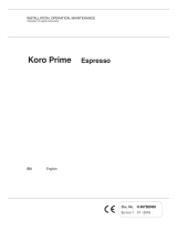
1.3.8. Technical data label
During the testing phase on the side of the Coin Mechanism
is placed a label with the data concerning the model
programmed in the Coin Mechanism.
The label reports the following data:
• product name;
• product code;
• name of the programmed model;
• programmed values (V);
• output/addressing (O = OUT);
• programmed channels (C).
fig. 12
In the first column on the left are indicated the values of the coins programmed in the model; in
the second column the addressing and the position of the tubes: 0 (zero) = Reject, 1-5 position
inside the Tube group, C = Cash; in the third column the programming channel used for the coin
storage in the model.
1.4.
Accessories available on request
1.4.1. Interface for electromechanical Automatic Vending Machine
To apply the Aeterna Change-Giver Coin
Mechanism to an Electromechanical automatic
vending machine (24V/110V/230V) it is
necessary to request any authorised Coges
dealer for the suitable interface corresponding
to the particular vending machine model.
Together with the interface
is supplied the
connecting harness.
fig. 13
AETERNA EXE
EUR (0.05/0.10/0.20/0.50/0.05)
952000 V=24V AC - Pmax=30W
1.01 CE
V O C V O C
EUR 0.01
EUR 0.02
EUR 0.05
EUR 0.10
EUR 0.20
EUR 0.50
EUR 1.00
EUR 2.00
0
0
1/5
2
3
4
C
C
1
2
3
4
5
6
7
8

16
CHAPTER 1
®
1.4.2. MDB Cashless System
In the Executive and BDV versions it is possible to connect any
cashless system with MDB protocol to the Aeterna Coin Mecha-
nism.
In addition to the normal sale and credit charge operations the
Key Reader permits to carry out the assisted loading of coins
inside the tubes of the Coin Mechanism (this function is available
only with MDB Coges cashless systems) by means of the recharge
key (see para. 2.1.7.3. “Loading by using the assisted loading
function”).
fig. 14
1.4.3. MDB Bill Validator
In the Executive and BDV versions it is possible to connect to the
Aeterna Coin Mechanisms a MDB Bill Validator.
The quick instructions for starting the Bill validator are supplied
with the product, while the user and maintenace manual is
available on the website: www.coges.eu at page Technical
support\ Download\ Technical manuals. Coges Bill validator is
connected to Aeterna Coin Mechanism by using the J7 connector
of the Base board (see para. 1.3.4. “Base board”).
fig. 15
1.4.4. Recharge Key
This function is available only with MDB Coges cashless systems. It is a normal
User Key which is enabled to the fast recharge of the tubes of the Coin
Mechanism without the need for entering the programming menu (see
para. 2.2. “Connections”). The key shall be enabled to the function by entering
the serial number in the proper menu item (see para. “11.19.2 Key Serial
Number List”) so that the system can recognize it. During the recharge
operation on the display of the Coin Mechanism is shown the number of coins
for filling the tube.
fig. 16
1.4.5. EXE-RS232 Interface for Systems and Change-giver
It is an interface which permits the connection of a cashless Execu-
tive system or an Executive Change-giver Coin Mechanism to a PC.
With this serial connection and the use of some special .dll files
concerning the Executive protocol commands (available on
request), the PC can simulate the operation of a vending machine
and thus can completely manage the payment system.
fig. 17

17
AETERNA CHANGE-GIVER COIN MECHANISM REL. 2.7
®
1.4.6. Accessories for programming and updating
In the Aeterna Coin Mechanism the parameter programming and the firmware update can be
carried out by using the following devices:
• Maxi Programmer;
• PC programming interface for systems/validators.
1.4.6.1. Maxi Programmer
Maxi Programmer is an instrument for programming Coges' devices, both Coin Mechanisms and
peripherals for coin and bill validation.
This instrument was designed in order to carry out the programming operations of the models
and/or the update of Flash memory, in a controlled and rapid way, permitting thus a direct
programming at the points of sale.
To carry out the firmware update it is necessary to ask
any Coges authorized dealer for the "Harness for Maxi
Programmer and TP606 ccTalk and PROFIT Validator" (see
para. “3.4.2.2. Firmware update by Maxi Programmer”
and para. “3.4.3.2. Model update by Maxi Programmer”
at the end of chapter 3).
With the same harness it is possible to carry out the
firmware update in the Base board (see para. “3.4.1.1.
Firmware update of the Base board by Maxi
Programmer” at the end of chapter 3).
For more detailed information on the programmer, refer
to the quick instructions of the device.
fig. 18
1.4.6.2. PC programming interface for systems/validators
The firmware update of the Base board of the Coin Mechanism is carried out directly by a PC
with the FlashManager software and the "PC programming interface for systems/validators",
which is available at any Coges authorized dealer. The interface is also used to update the
firmware of the Validator/Separator group (see para. 3.4.2. “Firmware update of the Validator/
Separator group”) and of the model inside the Base board (see para. 3.4.3. “Update of the
programmed model”).
fig. 19
1 = Minitek 10-ways connector
2 = Modu 10-ways connector
3 = SUB-D 9-ways connector for PC connection
4 = Switch for Flash/Parameters programming
5 = Yellow LED for Flash programming
6 = Green LED for power supply
7 = PC programming interface for systems/validators
1
2
3
4
56
7
Programmazione
parametri
Interfaccia di programmazione
per Sistemi e Riconoscitori da PC
Programmazione
Flash
Programmazione
Flash
Aliment
azione
®

18
CHAPTER 1
®
1.4.7.
Accessories for data recording
In the Aeterna Change-giver the data recording can be carried out by means of the following
devices:
• integrated IR interface;
• harness for serial communication to PC;
• IR PORT Module;
• Comunica Module;
• Printer for data recording.
1.4.7.1. Integrated IR interface
The Coin Mechanism is preset for recording the data directly from the infrared port by means of
a portable or palmtop PC (see para. “3.3.1. Aeterna Coin Mechanism” at chapter 3). The port,
which is placed on the front of the Coin Mechanism, is identified with the special label and the
IR symbol (see para. 1.3.5.2. “IR Label”).
1.4.7.2. Harness for serial communication to PC
It is a harness which permits the recording of the
accounting data of the Coin Mechanism in EVA-DTS format
by means of a serial connection. The same harness is also
used for connecting the Comunica Module to the Base
board of the Coin Mechanism. The harness can be
requested any authorized Coges dealer.
fig. 20
1.4.7.3. IR PORT Module
The IR PORT Module is a device equipped with an infrared interface which
permits the data recording in EVA-DTS format (
see para. “3.3.4. IR PORT
Module” at the end of chapter 3).
fig. 21
1.4.7.4. Comunica Module
It is a device which permits the GPRS connection of the different
sale points: vending machine, change-giver coin mechanism,
cashless system. It is equipped with some ports for the communi-
cation with the peripherals, 3 signalling LEDs for the user and a
base for removable SIM. The Module can draw the available data
in EVA-DTS format or in other serial proprietary protocols and
transfer them to a control centre in remote mode (see para.
“3.3.3. Comunica Module” at the end of chapter 3).
fig. 22
The information collected by means of the Comunica Module permits to improve the customer
service as it supplies: always updated sale statistics, control of sales and recharges, quantity of
products and cash in the vending machine and information about the events of the vending
machine (alarms included). This implies a detailed knowledge of the sale sites, improving thus
the management process and optimizing the technical assistance’s and the charging operators’
activities.

19
AETERNA CHANGE-GIVER COIN MECHANISM REL. 2.7
®
1.4.7.5. Harness for printer
The Base board of the Coin Mechanism is pre-arranged in order to
connect a printer which permits the accounting data recording (see
para. 1.3.4. “Base board”). The harness is available at any Coges
authorized dealer.
fig. 23
1.5. General Operation
The main feature of the Aeterna Change Giver Coin Mechanism is its ability to accumulate coins
inside the tubes and to return to the user any excess credit present after a sale. The operation of
coin accumulation and distribution occurs in three phases: recognition/separation, accumulation and
ejection.
When a coin is inserted in the Validator/Separator group, it is analyzed and compared with the
reference parameters present in the model. If the coin is validated, it enters the conveyor and then
it is addressed to the tubes or the cash.
The Coin Mechanism uses 2 groups of photocells which are placed in the lower and in the upper part
of each tube to check the level of the coins present at their inside and if necessary to make the
corrections to the coin counters. The coin counters present in the tubes permit to execute the
analysis and the calculation of the change composition.
When inside the tubes the maximum limit of coins is reached, the latters are automatically
addressed to the cash. This occurs with the validated coins too, which are not configured inside the
Tube group.
If the coin is not valid it passes directly from the Validator/Separator group to the Reject Channel.
All the operation phases of the Coin Mechanism and the programmed data concerning each operation
are shown on the display, which is placed on the front of the Validator/Separator group.
The Ejection group starts to work when the microprocessor signals the presence of a residual credit
after the sale operations. By means of the data set during programming the type of coin and the
number of pieces to be distributed are defined. The motors powering the cams, which are placed at
the base of each tube, permit to direct the coin to the return channel and then to the coin recovery
tray, which is at user's disposal.
1.5.1. Coin reading
At switching on the Aeterna Coin Mechanism displays: the
"Aeterna" inscription on the upper line and the number of coins
present in each of the 5 tubes into square brackets on the lower
line.
If the tube box results open, the display is this one:
When a coin is inserted in the Coin Mechanism on the upper line
of the display is shown the "Aeterna" inscription while on the
lower line are displayed the currency (ex. EUR) and the coin
value (ex. 0.10), the storage channel, which is occupied by the
coin just passed in the model (ex. C04) and the coin
destination (ex. tube 2 = 2).
<Aeterna>
[15 25 18 40 36]
<Aeterna>
15 25 18 40 36
<Aeterna>
EUR 0.10 C04 2

20
CHAPTER 1
®
If the destination tube is not available, if the value set in the
“12.8-12.1 Maximum Limit” item is reached or if the coin
destination is the cash, on the Coin Mechanism display is shown
the symbol of the cash ().
Furthermore there are some conditions where the programmed coins are given back to the user:
• when the machine where the Coin Mechanism is installed results to be out of order;
• when the value set in the “5.1 Maximum Cash Credit” item is reached;
• when the value set in the “5.2 Maximum Key Credit” item is reached.
In these cases on the display of the Aeterna Coin Mechanism is
shown the symbol of the rejected coin () and the coin is given
back to the user.
When in the Coin Mechanism is inserted a coin which is not
recognized, on the display appears the message "Unknown Coin"
and then the symbol of the rejected coin ().
1.5.2. Operation conditions
During the normal operation the Coin Mechanism displays the condition active at that moment,
that is the operating mode, by using a symbol displayed on the left of the lower line.
In the following table are listed the symbols diplayed and their meaning.
The single items of the programming menu are described in chapter 3; while the summary diagram
of all the programming items and the default data is available in the last pages of this manual.
SYMBOL MEANING
No peripheral is inhibited.
b Inhibition of the bills acceptance.
c Inhibition of the coins acceptance.
! Inhibition of the coins and the bills acceptance.
i Coin Mechanism in Exact Amount; peripherals are enabled.
B
Coin Mechanism in Exact Amount; inhibition of the bills
acceptance.
C
Coin Mechanism in Exact Amount; inhibition of the coins
acceptance.
¢
Coin Mechanism in Exact Amount; peripherals are inhibited.
iR
Coin Mechanism with the “EVADTS->IRDA” or “EVADTS -> IR
PORT” option selected in the “10.3.1 Device” item (it excludes
any operation with
EasyCoinProfit
).
)) Recording/transmission in progress.
PC
Coin Mechanism with the “EVADTS -> PC” option selected in the
“10.3.1 Device” item (it excludes any operation with
EasyCoinProfit
).
Coin Mechanism with the “Printer” option selected in the
“10.3.1 Device” item.
Coins disabled.
<Aeterna>
EUR 0.10 C04
<Aeterna>
EUR 0.20 C05
<Aeterna>
Unknown Coin
/