Page is loading ...

1
Form 1-738 R
JULY, 2003
INSTALLATION a
n
d
OPERATING
INSTRUCTION MANUAL
1.8 & 2.0 CU. YD. INSERT HOPPER SPREADER
with Replaceable conveyor Floor
SAFETY ALERT ............................................................................................................... 2
SPREADER ASSEMBLY INSTRUCTIONS ....................................................................... 3 - 5
ELECTRIC THROTTLE CONTROLS ................................................................................ 6 - 9
CENTER HIGH MOUNT STOP LAMP ............................................................................... 10 - 11
HYDRAULICS ............................................................................................................... 12 - 13
SPREADER OPERATION ................................................................................................. 14 - 17
SPREADER MAINTENANCE ............................................................................................ 18
SPREADER PARTS LISTS & EXPLODED VIEW
• HYDRAULIC MOTOR .................................................................................................... 19
• HYDRAULIC DRIVEN SPREADERS ............................................................................ 20 - 27
• ENGINE DRIVEN SPREADERS ................................................................................... 28 - 35
• DURST GEAR BOX ASSEMBLY .................................................................................... 36 - 37
• SUPERIOR GEARBOX ASSEMBLY .............................................................................. 38 - 39
•
SPINNER ASSEMBLY
•• SHORT ............................................................................................ 40 - 41
•• INTERMEDIATE “NEW STANDARD EQUIPMENT” ...................... 42 - 43
•• EXTENDED ..................................................................................... 44 - 45
•
ELECTRIC CONTROLS
•• HONDA ENGINE ............................................................................. 46 - 47
•• BRIGGS & STRATTON ENGINE .................................................... 48 - 49
• CONTROL BOX ............................................................................................................. 50 - 51
• OPTIONAL COMPONENTS .......................................................................................... 52 - 53
• PARTS LIST SHIPPING CARTON ................................................................................ 53
NAME PLATE INFORMATION .......................................................................................... 54
WARRANTY INFORMATION............................................................................................. 55
WARRANTY REGISTRATION CARD ................................................................................ 55
INDEX
Diamond Equipment
6 Angell Lane• Damariscotta, ME 04543-9720
Phone 563-2227(Area Code 207)
www.diamondplow.com • email info@diamondplow.com
Meyer Products
18513 Euclid Ave. • Cleveland, Ohio 44112-1084
Phone 486-1313 (Area Code 216)
www.meyerproducts.com• email [email protected]
Meyer Products and Diamond Equipment reserves the right, under its continuing product improvement program, to change construction or design details,
specifications and prices without notice or without incurring any obligation.
PART NO. CAPACITY LENGTH WEIGHT (EMPTY)
62209 (STEEL) 1.8 CU YD 7 FT. 980 LBS.
62517 (STEEL) 2.0 CU YD 8 FT. 1015 LBS.
62504 (STEEL) SPINNER ASSEMBLY
62505 (STEEL) SPINNER ASSEMBLY (EXT.)

2
!
THE BEST SAFETY
DEVICE IS A
CAREFUL OPERATOR!
SAFETY ALERT SYMBOL
THIS SYMBOL MEANS ATTENTION!
BECOME ALERT! YOUR SAFETY IS INVOLVED!
PLEASE READ AND UNDERSTAND COMPLETELY BEFORE DOING!
SAFE EQUIPMENT INSTALLERS
AND
OPERATORS:
TURN OFF ALL POWER BEFORE PERFORMING ANY SERVICE OPERATIONS
• FOLLOW RECOMMENDED OPERATING PROCEDURES.
• KEEP EQUIPMENT IN SAFE OPERATING CONDITION AT ALL TIMES.
• RECOGNIZE AND AVOID HAZARDS WHILE OPERATING, SERVICEING AND
MAINTAINING EQUIPMENT.
REFER TO THE ENGINE OPERATING & MAINTENANCE MANUAL FOR
SPECIFIC SAFETY PRECAUTIONS FOR THIS ENGINE.
!
!
NOTICE:
Instructional Material And Parts Lists Included In This Manual Are Subject To Change Without Notice.
CAUTION
1. KEEP ALL SHEILDS IN PLACE.
2. MAKE CERTAIN EVERYONE IS CLEAR BEFORE
STARTING MACHINE OR MOVING VEHICLE.
3. KEEP HANDS, FEET, AND CLOTHING AWAY FROM
ALL POWER DRIVEN PARTS.
4. DISENGAGE P.T.O., SHUT OFF HYDRAULIC VALVE
AND SET PARKING BRAKE BEFORE LEAVING
OPERATOR’S POSITION. MAKE SURE ALL
MOVEMENT HAS STOPPED BEFORE SERVING,
UNCLOGGING OR CLEANING MACHINE.
5. USE FLASHING LIGHTS WHEN OPERATING
MACHINE.
6. MAKE SURE MACHINE IS SOLIDLY SUPPORTED
WHEN IT IS BEING MOUNTED, DISMOUNTED, OR
STORED.
IF DEFACED • ORDER PART NO. 04049 045 00
!

3
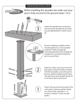
INSTALLATION AND ASSEMBLY INSTRUCTIONS
INSTALLATION INSTRUCTIONS:
The 1.8 and 2.0 Series Spreaders can mount and store as a single unit and will mount on most medium,
heavy-duty/pick-up trucks as well as 1 ton trucks
DO NOT OVERLOAD THE VEHICLE. It is quite possible to overload the vehicle by improperly mounting or over
loading the spreader. This could result in dangerous stability and braking problems. Always consult and follow the
truck manufacturer’s instructions.
BEFORE BEGINING ANY INSTALLATION ON THIS UNIT, disconnect the spreader battery negative cable if
already installed.
1. Place the Spreader in the rear of truck with the engine/hydraulic motor to the rear of the truck. Center the
spreader (side to side) in the truck. The spreader should extend past the rear of the outer most part of the truck
(i.e: truck bed, bumper) approximately 18 inches.
INSURE THAT THE SPREADER CANNOT TIP WHEN THE SPINNER ASSEMBLY IS ATTACHED
SPINNER ASSEMBLY
a. Raise engine shroud and prop it open with the support rod. (If engine driven model)
b. Slide the spinner frame assembly into the rear of the longitudinal with the spinner back plate toward the
rear.
c. Bolt the spinner to the longitudinals using the four (4) 3/8” x 1” bolts, 3/8” flange nuts and flatwashers from
hardware bag located on the spinner. Using one (1) 3/8” x 1” bolt, flatwashers and flange nut from hardware
bag, bolt the top portion of the spinner back plate to the engine plate.
d. Install roller chain between the gear box sprocket and the spinner sprocket.
Make sure sprockets are in line with each other. The roller chain is tightened first by loosening all four (4)
3/8” bolts on the back plate; then pull the entire bearing/shaft assembly in such a way to achieve the proper
amount of chain tension. Make sure the spinner shaft is straight up and down before
re-tightening.
2. Reposition the spreader in the truck, just short of making contact with the rearmost part of the truckbed,
bumper, pintle hook etc. Bolt the unit to the truck using a minimum of four (4) 1/2” - grade 5 bolts and
corresponding washers and locknuts.
The spreader is designed to sit flat on the bed of the truck, supported by the longitudinals/sides.
DO NOT SUPPORT THE SPREADER BY THE BODY JACKS ALONE!! UNIT IS NOT DESIGNED FOR
CHASSIS MOUNT APPLICATIONS!
THE SPREADER UNIT MUST BE SECURELY FASTENED TO THE VEHICLE. FAILURE TO NOT
PROPERLY RESTRAIN THE UNIT COULD PERMIT THE UNIT TO BREAK FREE FROM THE TRUCK
AND CREATE A POTENTIAL FOR A LIFE THREATENING ACCIDENT.
WARNING
WARNING
CAUTION

4
OPTIONAL HOLD-DOWN KIT
Part No. 62562 (00002-306-00)
INSTALLATION INSTRUCTIONS
READ ALL THE INSTALLATION INSTRUCTIONS BEFORE STARTING
Before starting, verify that this mounting is acceptable to the vehicle manufacturer.
Attach the hold down at each corner of hopper as shown. Locate and drill four .531
(17/32”) diameter holes for eye-bolts in the truck bed (position may vary from that shown). Straps must be
positioned at opposing angles so that spreader cannot slide forward or rearward. Mount eye-bolts as
shown, with locknuts and flatwashers on the bottom side. Assemble ratchet/strap to eye-bolts. Tighten
hold downs evenly. Do not over tighten damage will result to the spreader or the truck.
ITEM PART NUMBER QTY. DESCRIPTION
1 62602 04068-038-00 4 Ratchet/Strap
2 62807 04048-504-02 4 Bolt, 1/2” Eye
3 20307 04003-804-06 4 Locknut, 1/2-13 Esna ZP
4 62604 04003-801-11 4 Nut, 1/2-13 Hex ZP
5 62605 04004-002-16 8 Flatwasher, 3/4"
CAUTION
1
2
4
5

5
ASSEMBLY INSTRUCTIONS
1. Install roller chain between the gear box sprocket and the spinner sprocket. Make sure sprockets are in line with
each other. The roller chain is tightened, first by loosening all four (4) 7/16" bolts on the back plate. Then, pull the
entire bearing bracket assembly in such a way to achieve the right amount of chain tension. Make sure spinner
shaft is straight up and down before retightening.
2. Electric Throttle: Go to page 8.
Manual Throttle: Installation or replacement with gasoline engine do the following: Attach "Z" end of throttle
cable to engine throttle. Anchor brass shoulder end to engine with hold down. Drill 1/2" hole in truck cab for
control end of cable. The throttle handle can be removed to put throttle cable through drill hole. DO NOT MAKE
SHARP BENDS OR KINK THROTTLE CABLE. Use rubber grommet, supplied, in hole that you just drilled to
protect cable. Do not mount throttle cable assembly to switch bracket yet; upcoming assembly instructions will
become more difficult if throttle cable is mounted now.
Refer to diagram "A" on page 6-7 for installation and part ordering.
3. Run the (2) conductor cable (#16), which leads from the soleniod (white lead), and the electric clutch (black
lead) through the same hole which you put your throttle cable through.
4. Wire-up (2) conductor cable (#16) to the control panel as Diagram "A" shows; making sure the white conductor
is connected to the lone terminal of the push button (#3) and the black conductor to the lone terminal of the on/
off button (#7). The red wire (#6) which is about 4 ft. long, must be connected into the vehicles electrical system
so that it provides power to switch bracket. Control panel will not function without this connection.
5. Find a convenient location for the control panel and drill (2) 13/32" holes on 3" hole centers. Before mounting,
you may want to mount throttle cable to control panel according to diagram "A." Using the 3/8" x 1" bolts,
lockwashers and nuts, mount panel securely.
6. When finished, make sure all wires are away from moving parts and lower engine shroud.
CAUTION!
Never operate machine with engine shroud in the upright position. Never climb into hopper while the engine is
operating. SERIOUS INJURY or DEATH MIGHT OCCUR.
WARNING
Consult vehicle manufacturer for acceptable mounting locations. Improperly mounting the control box could interfere
with air bag(s) and the other functions of the occupant protection systems, such as knee bolsters!
Before mounting, you may want to mount throttle cable to control panel according to Diagram “A”.
Using the 3/8” x 1” bolts, lockwashers and nuts, mount panel securely.

6
DIAGRAM "A"
BATTERY
FRONT VIEW
REAR VIEW
BATTERY HOLD
DOWN POST
BLACK
WHITE
BLACK
WHITE
STARTER
CHARGER
WIRE
11
21
10
20
15
13
16
19
6
9
4
1
2
7
17
THROTTLE
3
14
5
12
18

7
Parts indented are included in the carton, bag or assembly under which they are indented.
** Includes items 1- 9
TABLE FOR
DIAGRAM "A"
ITEM PART NO. QTY. DESCRIPTION
62116 00001-598-00 1 Carton, Electrical Cab Controls
1 61216 00104-824-00 1 • Switch Bracket
2 62047 04640-004-00 1 • On/Off Plate
3 62038 04144-008-00 1 • Push Button Switch
4 62042 04616-013-00 1 • 16 Ga. Black Wire (6" Long)
5 61188 04143-024-00 1 • Throttle Cable Assembly
6 62043 04616-032-00 1 • 16 Ga. Red Wire (4' Long)
7 62049 04640-013-00 1 • On/Off Switch
8 62805 04638-040-06 1 • Insulated Spade Terminal
9 92805 04638-040-06 2 • Insulated Spade Terminal
10 62040 04604-004-00 2 • 19" Battery Cable
11 62046 04638-039-04 1 • Insulated Ring Terminal
12 61179 04146-005-00 1 • Grounded Solenoid
13 61167 04138-017-00 1 • Electric Clutch
14 •• Now part of item 13
15 61213 04616-067-02 1 • Starter Cable
16 62107 00111-162-00 1 • Cable Assembly, Rear Half
17 61152 00104-847-00 1 •
Assembly, Control Panel **
18 62108 00111-163-00 1 • Cable Assembly, Front Half
19 Not Used • T
ubing, Shrinkable 1/8" x 2"
20 62105 04067-033-00 1 • Boot, Battery Cable (Battery End)
21 62106 04067-033-00 1 • Boot, Cable (Solenoid End)

8
INSTALLATION INSTRUCTION FOR
ELECTRIC THROTTLE CONTROLS
(FACTORY INSTALLED ACTUATORS)
BEFORE BEGINING ANY INSTALLATION ON THIS UNIT, disconnect the spreader battery
negative cable if already installed.
PREPARING UNIT:
1. Spreaders with factory installed throttle controls do not require installer hook-up to the engine. The
actuator has been installed and tested at the factory.
2. Raise the engine shroud and securely prop it in place with the prop rod. The installer will have to remove
the ties securing the coiled actuator cable to the top of the engine.
3. The throttle actuator cable plugs into the in-cab control panel after being routed from the cab of the
vehicle to the rear of the mounted spreader.
4. Select a suitable location in the cab of the vehicle to mount the throttle control box.
Consult vehicle manufacturer for acceptable mounting locations. Improperly mounting the control box could
interfere with air bag(s) and the other functions of the occupant protection systems, such as knee bolsters!
5. After the location of the control panel is determined, the cable must be routed to the front of the spreader,
Route cable under the cab and up to the front of the spreader securing as needed. Allow enough cable for
the control panel to be mounted in the cab.
6. The routed cable must be clear of all moving or hot parts on the sreader or vehicle. Secure the cable with
the ties provided. Excess cable must be coiled up and secured. Apply dielectric grease on Item # 21
page 46 for protection from salt spreading envoirment.
7. Mount the control panel (with screws supplied).
8. For permanent cable mount at rear of the truck, a mounting bracket is supplied.
9. Install a 12 volt battery with 40 ampere hour rating, recommended for winter use (if not already done). The
battery hold-downs furnished will accept any 2 SM Series battery.
WARNING
WARNING

9
WARNING
USE SAFETY GLASSES OR OTHER FACE PROTECTION AGAINST POSSIBLE BATTERY
EXPLOSION. DO NOT SMOKE AND AVOID OTHER SOURCES OF IGNITION.
10. Attach the positive battery cable (each end should have a rubber boot) to the positive terminal of the
solenoid and to the positive terminal of the battery. Make sure these protective boots are covering the
positive terminal post on the battery and on the solenoid. Attach one end of the remaining battery cable
to the negative terminal of the battery.
11. Connect the negative battery terminal to the battery hold down post. When finished, make sure all
wires are away from moving parts and lower engine shroud.
12. Plug cable from spreader into socket mounted on truck.
Never operate machine with engine shroud in the upright position. Never climb into hopper
while the engine is operating or capable of being operated.
SERIOUS INJURY or DEATH MIGHT OCCUR.
NOTE: Read and fully understand the owners manual supplied by the engine manufacturer
before operating this equipment. Not doing so, endangers your safety and the warranty
of the engine.
WARNING

10
CENTER HIGH MOUNT STOP LAMP (CHSML)
Federal Motor Vehicle Safety Standards require all Trucks, Buses, and Multipurpose passenger
vehicles, manufactured on or after September 1, 1993, with a gross vehicle weight rating (GVWR)
of 10,000 lbs. or less and overall width less than 80" must be equipped with a Center Height
Mount Stop Lamp (CHMSL).
If the original equipment CHMSL is obscured, an auxiliary CHMSL must be installed to bring
vehicle back into compliance with Federal Regulations.
Electrical Connection for Auxiliary CHMSL:
(Notes for all truck makes)
1. Use high quality butt connectors and shrink wrap on all electrical splice connections. Wire should be routed
and secured to protect against abrasion, sharp edges, excessive movement. It is highly recommend that
wiring to be placed in convoluted tubing and secured with tie wraps.
2. When drilling holes, any bare metal should be coated with a rust preventative, use appropriate size grommets
and seal hole with appropriate sealant.
3. Allow for normal movement / twisting between cab and chassis / pickup box when routing wires.
4. When spreader is removed from the truck, the OEM CHMSL must be reconnected.
Consult the truck manufacturer for an approved method of connecting an auxiliary CHMSL to the particular truck
which is to carry the Spreader. Methods vary with truck models, optional equipment and years of manufacture.
IMPROPER CONNECTIONS COULD RESULT IN A VARIETY OF PROBLEMS AFFECTING CRITICAL SYSTEMS
SUCH AS BRAKING, ELECTRICAL AND EMISSION ! DON'T GUESS !
PV Spreader CHMSL Installation:
Mount power cable (04616-075-00) with plug at rear of truck frame and route to truck CHMSL power feed. Trim
excess cable length, attach white wire to suitable ground, attach black wire to truck's CHMSL power feed.
Connect cable on spreader to CHMSL power cable.
When the spreader is removed from the truck, the OEM CHMSL must be reconnected.
WARNING
WARNING

11
CENTER HIGH MOUNTING STOP LIGHT
ITEM PART NUMBER QTY. DESCRIPTION
62097 00002-144-00 1 Kit, Center High Mount Stop Light
1 62714 04605 153 00 1 • Lamp, Stop
2 62715 04605 154 00 1 • Grommet
3 62364 04605 155 00 1 • Cable, Light Power
4 62738 04616 075 00 1 • Cable, Stop Lamp
5 62283 00111 339 00 1 • Weld, Stop Lamp Bracket - Hydraulic Units ONLY
6 62739 00111 428 00 1 • Hardware Bag - Not Shown
(GAS ENGINE)
(HYDRAULIC)
3
4
2
1
2
1
5

12
HYDRAULICS
LEAKING HIGH PRESSURE FLUIDS CAN INJECT THEMSELVES UNDER THE SKIN OF PERSONS
NEAR A LEAK, CREATING GRAVE MEDICAL RISKS. TAKE CARE TO AVOID EXPOSURE TO
HIGH PRESSURE FLUIDS.
1 . Hydraulic components should be kept as clean as possible during assembly operations.
2. Galvanized pipe and pipe fittings must not be used because flaking or galvanizing material can cause
damage to major hydraulic components.
3. A pipe joint sealant, compatible with hydraulic oil, must be applied to all screwed fittings. (Teflon tape is not
recommended.)
4. Hose should be protected where severe wear may be caused by vibration or sliding movement.
5. Long runs of hose should be supported by tie wiring or clamping.
6. Pressure and return hoses, connected to hydraulic motors, may be reversed for proper motor rotation.
Spinner rotates in a clockwise direction when looking down from top.
7. Use hose manufacturer’s recommendations for fitting re-useable hose ends.
8. Hydraulic pumps must be mounted so shaft rotates in direction of arrow.
9. Locate reservoir as close to pump as possible. It may be installed on truck frame or truck box.
10. Hydraulic return line filter is screwed directly onto reservoir with cartridge down. Oil must flow through filter
in direction of arrow on filter.
11. Install the quick connect couplings so that when disconnected, there is a male and female on the truck as
well as on the spreader. This way, hoses will always be hooked up properly. and hose ends can be coupled
together when spreader is in storage to prevent system contamination.
12. See page 13 for valve assembly
13. Operate hydraulic system for several minutes to warm up. Check all connections for leaks.
14. After running, refill reservoir to three fourths full.
CONTROL AND HYDRAULIC SYSTEM SPECIFICATIONS
* Hydraulic Oil ................................. Good Grade of MS10W Hydraulic Oil Which has
wear, oxidation and foam inhibitors.
* Oil Filter ........................................ 10 Micron Element Return Line Filter.
* Relief Valve Setting ...................... 1500 PSI
* Oil Flow......................................... 0 - 10 GPM
WARNING

13
BOTTOM VIEW
A - A
(SHOWN W / O FITTINGS)
61190
(04105-306-00)
S
IN
G
LE FL
O
W
CO
NTR
O
L VALVE
FLANGE PLATE
00105-873-00
8.0"
HOSE SLACK
AFTER PLUMMING
A
A
VALVE STAND
(2) HALVES
00105-874-00
TRUCK CAB
FLOOR BOARD
*
DUAL FLOW VALVE/STAND
INSTALLATION INSTRUCTIONS
1. IMPORTANT: A pipe joint sealant compatible with
hydraulic oil must be applied to all screw fittings.
(Teflon Tape Sealant Is Not Recommended)
2. Hose ends connected to flow valve must be of the
"swivel" type.
3. CAUTION: Over tightening of the fittings in flow valve
may cause damage to valve body.
4. Approximately 8" of hose slack must be realized
between the flow valve and valve stand after the
flow valve has been completely plumbed. If this
condition does not exist after the plumbing has
been completed, removal of valve will require hoses
to be removed at opposite end of valve.
5. Assembly of valve on stand:
a. Cut a 5" x 5" square opening in floor board of
truck where the valve stand is to be located.
b. Bolt valve stand halves together forming a
"box" over the 5" x 5" square opening. NOTE:
When bolting valve stand halves in place,
make sure holes in flanges align with holes in
flange plate.”*”
c. Bolt flange plate to VALVE (Use (2) 1/4" x 3"
bolts, lockwashers, etc.)
d. Insert hoses through floor opening and valve
stand and connect appropriate hoses (see
instructions #1 thru #4) to flow valve.
e. Bolt flange plate to valve stand flanges.

14
BEFORE OPERATING THE CONTROL PANEL - MAKE SURE THAT NO ONE IS INSIDE
THE HOPPER OR NEAR THE SPINNER.
1. Manual Throttle: All gasoline engine models come with a control panel. If your spreader is a manual
throttle model, look at your control panel. It will have (3) controls
mounted on it. The one on the far left is the start button. The right toggle is the electric
clutch control. When the switch is in the “OFF” position, the electric clutch is disengaged
and the conveyor and spinner will stop. In the “ON” position, conveyor and spinner will operate. The
middle control is the throttle. Your engine is equipped with a semi- automatic choke. To activate
the choke, pull the throttle cable all the way out. To remove the choke function when engine us warm,
push throttle cable in, to desired engine RPM.
WARNING
OPERATION
2. Electric Throttle Control Panel Switch Functions
(Sequence of Operations)
THROTTLE
START
ON
OFF
ON
OFF
CHOKE
START
RED LENSE
THROTTLE

15
WARNING
1. As with all power equipment, safety is the number one concern.
2. Do not operate this equipment until you fully understand how it functions.
3. Before starting engine, be sure that no one is near the rear of the unit and that no one is inside the
unit!
4. Do not start the engine or engage the conveyor (which is interconnected to the spinner); until everyone
is clear from moving parts and flying material from the spinner.
Electric Throttle Control Panel Switch Functions Cont.
A. ON/OFF System power activated (ready to start). Spreader engine is not running.
Spreader conveyor is not engaged.
B. START (Engine only)
1. Open fuel shut off valve on engine.
2. On On switch depressed.
3. Choke (cold engine ) Hold down for 5 seconds to move the throttle actuator to
the choke position.
Note: Choking a warm engine may not be necessary.
4. Start Hold down until engine starts.
4a. On models with 6.5 HP at temperatures under minus 20
o
F (minus 29
o
C) it mat be
necessary to start the engine manually.
5. Turtle Deceases throttle speed - adjust as engine warms up. Will stop the choke function.
Rabbit Increases throttle speed.
C. TO ENGAGE Spreader Conveyor
1. Push CONVEYOR switch only after you are sure no one is in the hopper or near the spinner! This lights up
the red indicator light, if light does not light, take care to verify that the light is not malfunctioning.
D. TO CONTROL Conveyor Speed.
1. Hold RABBIT to increase speed. NOTE: Do not hold switch in HI position after the desired RPM is achieved
or you will choke and/or stall the engine.
2. Hold TURTLE to decrease speed.
E. TO DISENGAGE Spreader Conveyor.
1. Tap START switch momentarily so that red indicator light goes out. Do not fully depress the START switch,
only half way is needed. Only the conveyor stops, the engine continues to run.
F. TO TURN ENGINE OFF (with or without conveyor running).
1. Depress LO on throttle control to reduce setting to idle (this prevents engine flooding and hard starting).
2. Push OFF position on the ON/OFF switch.
NOTE: OFF can be pushed at anytime during spreader operation to cut power to the unit . However, you
should normally use steps under F above.
(Once the off switch is depressed - the starting procedure must be followed for engine re-start.)
G. Do not attempt to start the engine with the conveyor engaged. (CONV switch light will be lit to indicating its'
being on.)
H. Close fuel shutoff valve on engine if unit is to be transported while not running.

16
SPREADER OPERATION
A. Start the engine and engage the clutch. The amount of material spread, depends on engine speed and gate
opening. Decreasing RPM and/or gate height will decrease amount spread; the inverse holds true also.
Notice that the electric clutch can be engaged or disengaged at any time and at any engine RPM. However,
since engagement time and torque is almost instantaneous, to prevent premature spinner chain failure and
chain tension loss, it is recommended that the electric clutch be engaged at the lowest possible RPM
without stalling the engine.
If the truck is to be driven for an extended period of time while the spreader is not operating, it is RECOMMENDED
to turn off the gas at the carburetor inlet to prevent the carburetor from over filling with fuel.
Before loading the spreader the first time, start and stop the conveyor several times to break in the clutch.
ALWAYS STAND AT A SAFE DISTANCE AWAY FROM THE SPINNER WHILE OPERATING
ALWAYS WEAR EYE PROTECTION WHEN OUTSIDE OF THE TRUCK CAB WHILE
SPREADER IS RUNNING.
B. Spread pattern depends on baffle settings and spinner RPM. Maximum spreader width is 30 ft.
1. Speeding up or slowing down the engine will increase or decrease spread pattern width.
2. Internal baffle adjustments will move the spread pattern to the right or left.
3. External baffle adjustments will block spreading to the right or left side.
DESIRED SPREAD PATTERN BAFFLE SETTING
INTERNAL EXTERNAL
CENTERED BEHIND TRUCK BOTH DOWN ALL THREE UP
BEHIND TRUCK AND LEFT RH - DOWN RH - DOWN
LH - UP LH - UP
BEHIND TRUCK AND RIGHT RH - UP RH - UP
LH - DOWN LH - DOWN
WINDROW BEHIND TRUCK RH - DOWN ALL - DOWN
LH - DOWN
4. External Baffles can be lowered to an intermediate position to baffle down the particles that may otherwise
leave the spinner at a high trajectory.
WARNING

17
June, 2000
SERVICE BULLETIN NO. 178
1.8, 2.0 and MDV Insert Hopper Spreader
Briggs & Stratton Corporation and Honda Engine Motor of America have stated in
their manuals:
DO NOT TRANSPORT ENGINE WITH FUEL IN TANK OR WITH FUEL
SHUT-OFF VALVE OPEN.
Failure in doing this may cause the engine crankcase to fill with fuel. If this occurs the
engine warranty will be void by the engine manufacturer. It is the responsibility of the
end user to ensure that the fuel shut-off is closed when the engine is not in operation.

18
DO NOT ATTEMPT TO LIFT THE SPREADER BY THE CENTER LIFT OR CORNER LIFT HOOKS
WITH MATERIAL IN THE SPREADER.
BEFORE BEGINNING ANY MAINTENANCE ON SPREADER, DISCONNECT SPREADER
BATTERY LEADS.
1. Grease idler bearings on idler shaft takeup assembly, outboard bearing on gearbox output shaft, and
lower spinner bearing every ten hours of operation.
2. Grease input shaft bearing on gearbox every fifty hours of operation. CAUTION! Over greasing may
cause seal damage. The gearbox must be filled to oil level plug with SAE 90 gear type lubricant. Keep
breather plug clean.
3. Drag chain slack on V-boxes should be checked periodically and taken up if distance between center line
of rear sprocket and point where chain contacts lower flange on longitudinal is less than eight (8) inches.
CAUTION! Over tightening conveor chain can cause serious drive train problems. Above distance must
not exceed 20 inches.
4. If the spreader is equipped with a gasoline engine, it should be maintained per engine manufacturer's
instruction. (Instructions and parts book is enclosed.)
5. V-belt tension must be maintained. The v-belt can be tightened by loosening engine hold-down bolts and
sliding engine as required. CAUTION! Over tightening of v-belt may damage gearbox.
6. Roller chain tension must be maintained. It is adjusted by loosening the spinner mounting bearings and
sliding the bearings. Make sure the spinner shaft is straight up and down before retightening. Oil chain
often and at end of season.
7. When the box is not in use, it should be washed out. If the box is put in storage, all surfaces should be
oiled or painted after washing.
8. For HYDRAULIC SPREADERS, maintain oil level three fourths (3/4) full in reservoir with clean high grade
non-foaming hydraulic oil; recommended viscosity 100-200 SSU. Operating temperature should be limited
to 180°F. Replace filter cartridge No. 62382 (04104 005 00) at least twice a year.
9. If chain becomes stuck or "froze" to the floor to the point where the clutch cannot pull the load, never
attempt to free chain using a pipe wrench or any other tool on the output shaft. The gearbox is designed
to accept torque from input shaft only. Trying to turn output shaft will strip the gears, thus voiding the
warranty.
10. To minimize problems and extend the life of the Electric Clutch, the following is highly recommended.
a. Before starting unit, make sure the drag chain is free (not stuck or "froze" to the
floor). If the drag chain is stuck, this can cause the clutch to burnup.
b. After the using season is over, remove clutch from unit, and clean thoroughly.
c. After cleaning, coat both mating surfaces of the clutch with oil or light weight
grease.
NOTE: The Oil or Grease must be removed prior to the next using season.
WARNING
MAINTENANCE

19
PARTS LIST FOR HYDRAULIC MOTOR
60324 (04101-035-00)
ITEM PART NUMBER QTY. DESCRIPTION
1 20644 04101-035-01 4 Screw, 5/16" - 24 x 7/8"
2 —————— —————— 1 Seal
3 62118 04101-102-02 1 Flange, Mounting (4 Bolt)
4 —————— —————— — Seal, O-Ring
5 62756 04101 035 05 1 Race, Bearing
6 —————— —————— — Seal, O-Ring
7 62757 04101 035 07 1 Bearing, Thrust Needle
8 21203 04009 002 02 1 Key, 1/4" x 1" Woodruff
9 62758 04101 035 09 1 Shaft, Output
10 62809 04101 035 10 1 Housing
11 —————— —————— — Seal, O-Ring
12 62759 04101 035 12 1 Drive (For 04101 035 00)
13 62760 04101 035 13 1 Plate, Spacer
14 62761 04101-035-14 4 Screw, 5/16" - 24 x 1 1/2" Cap
15
62814 04101 035 15 1 Gerotor Set (For 04101 035 00)
16 62405 04101 035 17 1 Cap, End
17 04101 035 18 7 Washer, Seal
62762 04101 035 21 1 Repaired Motor
(for 04101 035 00)
62406 04101 102 09 1 Seal Kit (Char-Lynn)
62359 04101 035 98 1 Seal Kit (White)
PARTS LIST
1
2
3
4
6
5
7
8
9
10
11
12
13
14
15
16
17
11
11

20
HYDRAULIC DRIVEN HOPPER SPREADER
25
18
19
26
27
28
29
11
5
28
29
43
56
2
28
29
43
41
40
44
23
1
3-43
4
6
7
8
10
12
13
13
54
16
18
19
31
19
20
21
17
16
54
42
12
35
21
34
34
?
used with
gas engine?
30
/