Page is loading ...

SWNDSTREAM@
T
E C
H
N
0
L
0
G
I
E
S
SWNDS-
T
E C
H
N 0
L
0
G
I
E S
RUBICON
805/405
513
Channel
Power Amplifiers
Owner’s Manual
and
Installation Guide
SOUNDSTREAM TECHNOLOGIES
120 Blue Ravine Road
-
Folsom
-
California 95630 USA
ph 916.351
.I288
-
fax 916.351.0414
m/A-ivwl8

Congratulations!
YOU now own the Soundstream
RUBICON
amplifier, the
product
of
an
uncompromising design and engineering philosophy. Your
Soundstream
RUBICON amplifier will outperform any other amplifier in the world.
To maximize the performance of your system, we recommend that
you
thoroughly acquaint yourself with its capabilites and features. Please
retain this manual and your sales receipt for future reference.
Soundstream amplifiers are the result of American innovation and
craftmanship
with the highest quality control standards. When properly
installed, they will provide you with many years of listening pleasure.
Should your amplifier ever need service or replacement due to
theft,
please record the following information which will help protect your
investment.
Model and Serial #
Dealer’s Name
Date of Purchase
Installation Shop
Installation Date
Prolonged listening at high levels may
resuR
in
heating
loss.
Even though
your
new
Soundstream
Rubicon
amplifier sounds
better
than
anyfhing
you’ve ever heard, exercise caution
to
prevent hearing damage.
Table of Contents
Design Features
.......................................................
p4-5
Rubicon
Amplifier Diagram
.................................
~6-7
Rubicon
Amplifier Diagram
.................................
p8-9
Crossover Adjustments
............................................
P
10
Hawkins Bass
ControlTM
Theory and Use
................
p 11
Installation: Speaker Output Modes
........................
P
12
Installation: Wiring
...................................................
P
13
Installation: Mounting
..............................................
P
14
Installation:
Level Setting and Front Spoiler
............
p 15
Sample System Diagrams
........................................
p
16-20
Protection Circuitry, Service and
Trouble&
Specifications
. . . . . . . . . . . . . . . . . . . . . . . . . . . . . . . . . . ..*.......
3
looting . . . p 21
. . . . . . . . . . . . . . .
P 22

DESIGN FEATURES
RUBITM(_Rapid-Use
Branched Impulse) This new proprietary power
supply topology eliminates “power sags” during low frequency repro-
duction by rapidly increasing the duty cycle, stabilizing the power sup-
ply and allowing it to deliver the power required when reproducing low
frequencies. Also, greater reserve gate power is stored for low volt-
age conditions that occur during extreme conditions.
STACTTM
(STabilized
Apex
current
_Topology)
Reduces power sup-
ply stress by 50%. Typical designs degrade the stereo image due to
phase reversal of even-order harmonic distortion that occurs between
the inverted channels. In the STACT design, inversion is done at the
power amplifier drive stage. Since the fully symmetrical power ampli-
fier produces no even-harmonic distortion itself and all preamplifier
circuitry is run completely in-phase, no even harmonic distortion phase
reversal occurs.
TridentTM
Protection Topology provides three types of protection:
1. Output protection against short circuits or improper loads.
2.
Ground fault detection: Shuts down the amplifier when a significant
voltage
(>5
Volts) fluctuation occurs between electrical (turn-on lead)
and battery ground.
3. Thermal Protection: Puts the amplifier into thermal rollback or shuts
the amplifier down in extreme thermal conditions.
Hawkins Bass Control
provides a focused subwoofer boost (O-9
dB
at 45 Hz) and routes otherwise wasted amplifier power back to the
audible bandwidth.
Harmonic Bass Alignment
TM
The 2nd and 3rd order harmonic peaks
are critically aligned to fundamental peaks at low frequencies. This
produces tighter, more accurate bass reproduction.
Drive Delay
IITM
Amplifier section powers up 2 to 3
seconds after the
power supply eliminating turn-on pops. Turn off process is reversed:
Amplifier section turns off first, followed by the power supply.
Dynamically Optimized Power Grid
TM
Power
grid is evenly distrib-
uted between primary and secondary power supplies, providing greater
dynamics and improved RF filtering.
ChassisinkTM
All transistors are ideally located and sandwiched be-
tween the circuit board and the heatsink to provide cool efficient ampli-
fier operation.
Differentially Balance RCA Input
eliminates ground loop related noise
in the audio.
Continuously Variable Crossover Networks: 12 dB/Octave 2-way
highpass variable from 65 to 220 Hz and 24 dB/Octave lowpass cross-
overs variable from 30 Hz to 120 Hz. 805
only
-
12 dB/Octave 3-way
crossover which can be selected for mid-bass (65 to 500 Hz) or
midrange
(65
to
4,000
Hz) operation.
.
Rear Channel De-Emphasis (805 only) A circuit based on theater
surround technology in which rear fill information is rolled off with a -3
dB
point at 7,000 Hz following with a 6 dB/Octave slope to provide a
more realistic listening experience (in 5 channel mode only).
Flexible Dual Input Level Control allows 300
mV
to 5 V input sensi-
tivity.
Symmetrical Discrete Balanced Class A Drive Boards Auto-ad-
just for linear performance while driving low impedance loads.
Removable Front Spoiler allows for stealth installation of RCA, Bal-
anced Line, Speaker and Power wiring.
4
5

-16
-18
-19
-20
--22
23
--24
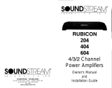
Front View
6
26-
L
Bottom View
1.
2.
3.
4
.
5
.
6.
7.
8
.
9
16.
11.
12.
13.
14.
15.
16.
17.
18
19:
20.
21.
22
23:
24.
25
26:
27.
KEY TO
CALLOUTS
Fuse
LED
-
Indicates blown power supply fuses when lit.
Power LED
-
Indicates amplifier power.
Low Pass XOVER
Switch -
(Subwoofer Channel) Select “IN” for use with
the internal crossover, or “OUT” for use with external crossover.
Subsonic
I
Hawkins Bass Control Switch -
Select “SUB SONIC” to engage
the Sub Sonic
filter
at 13 Hz. Select “HAWKINS BASS CONTROL” to engage
the subwoofer channel’s high pass filter
@
45 Hz with variable
“Q”
for optimum
bass.
Subwoofer Channel Input Select -
Selectable inputs from internal (CH
l-
4) or external (‘SUB”
-
local RCA inputs).
High Pass XOVER Switch
-
(Channels l&2) Select “IN” for use with the
internal crossover or “OUT” for use with external crossover.
High Pass XOVER Switch
-
(Channels
3&4)
Select “IN” for use with the
internal crossover or “OUT” for use with external crossover.
Channels
38~4
Input Select
-
Selectable inputs from internal (CH
l&2)
or
external (CH
3&4
local RCA inputs).
Inputs
-
Right and left channel RCA inputs for channels
3&4.
Input Level
-
Channels
3&4
input level control.
High Pass Filter Control Adjustment
-
(Channels
3&4)
crossover frequency
control for the internal high pass filter.
Speaker Connection Terminal
-
Speaker connections for Ch’s
3&4.
Inputs
-
Right and left channel RCA inputs for channels
l&2.
Input
Level
-
Channels
l&2
input level control.
High Pass Filter Control Adjustment
-
(Channels
l&2)
crossover frequency
control for the internal high pass filter.
Speaker Connection Terminal -
Speaker connections for Ch’s
l&2.
Inputs
-
Right and left channel RCA inputs for the subwoofer channel.
Input Level
-
Subwoofer channels input level control.
Low Pass Filter Control Adjustment
-
(Subwoofer Channel) crossover fre-
quency control for the internal low pass filter.
Hawkins Bass Control “Boost” Adjustment
-
Varies from 0 to
+9
dB
of
boost when the Hawkins Bass Control is engaged.
Speaker Connection Terminal
-
Speaker connections for Subwoofer Chan-
nel.
REMOTE - Remote turn-on input from the head unit. Accepts
+12V.
GND -
Main ground connection. Bolt to a clean chassis point in the vehicle.
+12V
-
Connected to a fuse or circuit breaker, then to the battery’s positive
terminal.
Main Fuse
-
Main power supply fuses.
Stereo/Mono Switch
-
(Channels
l&2)
Select “MONO” for bridged mono
output in 3 channel operation (use right RCA input only). Select “STEREO”
for stereo output in 5 channel operation.
Stereo/Mono Switch -
(Channels
3&4)
Select “MONO” for bridged mono
output in 3 channel operation (use right RCA input only). Select “STEREO”
for stereo output in 5 channel operation.
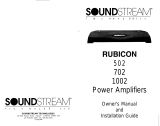
7

KEY TO
CALLOUTS
I
--__
i
-1‘27
,
i \
\
\
‘._
8
1.
2.
3.
4.
5.
6.
7.
8.
9.
IO.
Il.
12.
13.
14.
15.
16.
17.
18.
19.
20.
21.
22.
23.
24.
25.
26.
27.
28.
29.
30.
31.
Power LED
-
Indicates amplifier power.
Subsonic I Hawkins Bass Control Switch
-
Select “SUB SONIC” to engage the
Sub Sonic filter at 13 Hz. Select “HAWKINS BASS CONTROL” to engage the
subwoofer channel’s high pass filter
@
45 Hz with variable “Q” for optimum bass.
Low Pass XOVER Switch
-
(Subwoofer Channel) Select
YN”
for use with the internal
crossover, or “OUT,, for use with external crossover.
Subwoofer Channel Input Select
-
Selectable inputs from internal (CH
l-4)
or ex-
ternal (“SUB”
-
local RCA inputs).
Mid-Bass/Midrange Select
-
Selectable mid-bass or midrange frequency control in
3-way operation.
High Pass XOVER Switch
-
(Channels l&Z) Select “IN” for use with the internal
crossover or “OUT” for use with external crossover.
High Pass XOVER Switch
-
(Channels
3&4)
Select “IN” for use with the internal
crossover or “OUT” for use with external crossover.
Rear Fill
Deamphasis
Switch
-
(Channels
3&4)
Select “IN” to activate 6 dB/Octave
filter
@
7
kHz.
Channels
3&4
Input Select
-
Selectable inputs from internal (CH
l&2)
or external
(CH
3&4
local RCA inputs).
Inputs
-
Right and left channel RCA inputs for channels
3&4.
Input Level
-
Channels
3&4
input level control.
High Pass Filter Control Adjustment
-
(Channels
3&4)
crossover frequency con-
trol for the internal high pass filter.
Speaker Connection Terminal
-
Speaker connections for Ch’s
3&4.
Inputs
-
Right and left channel RCA inputs for channels
l&2.
Input Level
-
Channels
l&2
input level control.
High Pass Filter Control Adjustment
-
(Channels
l&2)
crossover frequency con-
trol for the internal high pass filter.
3,way Filter Control Adjustment
-
Channels
l&2
3-way high pass crossover fre-
quency control and channels 3&4 3-way low pass crossover frequency control.
Speaker Connection Terminal
-
Speaker connections for Ch’s
18~2.
Inputs
-
Right and left channel RCA inputs for the subwoofer channel.
Input Level
-
Subwoofer channels input level control.
Low Pass Filter Control Adjustment
-
(Subwoofer Channel) crossover frequency
control for the internal low pass filter.
Hawkins Bass Control “Boost” Adjustment
-
Varies from 0 to
+9
dB
of boost when
the Hawkins Bass Control is engaged.
Speaker Connection Terminal
-
Speaker connections for Subwoofer Channel.
REMOTE
-
Remote turn-on input from the head unit. Accepts
+12V.
GND
-
Main ground connection. Bolt to a clean chassis point in the vehicle.
+12V
-
Connected to a fuse or circuit breaker, then to the battery’s positive terminal.
Main Fuse
-
Main power supply fuse.
Stereo/Mono Switch
-
(Channels
l&2)
Select “MONO” for bridged mono output in 3
channel operation (use right RCA input only). Select “STEREO” for stereo output in
5 channel operation.
2-way
I
3-way
Switch
-
(Channels
l&2)
Select
“2-way”
for 2-way internal crossover.
Select
“3-way”
for
3-way
(band pass) internal crossover.
Stereo/Mono Switch
-
(Channels
3&4)
Select “MONO’ for bridged mono output in 3
channel operation (use right RCA input only). Select “STEREO” for stereo output in
5 channel operation.
2-way
I
3-way Switch
-
(Channels
l&2)
Select “2-way” for 2-way internal crossover.
Select
“3-way”
for 3-way (band pass) internal crossover.
9

CROSSOVER ADJUSTMENTS
Hawkins Bass Control
-
Theory and Use
The
RUBICON
amplifiers incorporate an on-board staggered electronic cross-
over, with RCA outputs to drive an external amplifier. No external electronic cross-
over is necessary. However, if you do desire to use an external crossover you still
have the option.
The high and low pass portions of the crossover can be set
independently of one another.
In many car audio installations, there is a tendency for a “midbass boom.” Be-
cause of their interior dimensions, most cars will resonate or ring at these midbass
frequencies. If we design the system so there is reduced output in this region, the
final response is very smooth and natural sounding. The high pass crossover is
independently variable from 65 to 220 Hz at 12 dB/Octave, and the low pass
crossover is independently variable from 30 to 120 Hz at 24 dB/Octave.
For initial crossover setup, try setting the low pass filter to approximately 60 Hz,
and the high pass filter to approximately 100 Hz. Change the crossover points to
accommodate a good mixture of frequency response, power handling, and per-
sonal preference.
2-WAY
12 dB/Octave High Pass
39WAY
(805 ONLY)
MIDBASS/MIDRANGE BAND PASS
The
RUBICON
can be operated in midrange or
midbass
“band pass” con-
figuration. In the three way mode, you can tri-amplify with “active” midbass or
midrange to maximize control over individual drivers. The
bandpass
includes
a low pass and high pass filter, which work independent of one another, to
drive the midrange or
midbass
speakers.
39WAY
12 d B/Octave
12 dB/Octave
High
Pass
Low
Pass
1
High
Pass
10
Hawkins Bass Control (variable) is a unique subwoofer con-
trol circuit included with the Soundstream
RUBICON
&
805
amplifiers. It is capable of removing subsonic energy in pro-
gram material below 45 Hz at 12 dB/Octave, while boosting
subwoofer frequencies. The circuit consists of two controls. One
engages a subsonic High Pass filter at 45 Hz, and the other
adjusts the amount of boost (0 to
+9
dB).
The Boost control adjusts the amount of level applied at the
set frequency, and is adjustable from 0 to
+9
dB
(see figure 2).
When the boost is set to 0, Hawkins Bass Control
a,cts
as a sub
sonic filter only. The simple act of removing potentially harmful
low frequencies can improve system output by as much as 3
dB.
Application
10
Subwoofer drivers in general have excellent
5
power handling characteristics over their
z
operational bandwidth. This bandwidth is de-
dB.,0
termined by many factors, including driver
-15
design and enclosure type. It is possible to
-20
overdrive any subwoofer driver by sending
I’,:
powerful signals outside of its operational
bandwidth. These potentially damaging
sig-
SUB
HAWKINS
SONIC
l BASS
CCNTRl3L
HA’tVKINS
EASS
I
CONTROL
FIG.
1
’
3 Frequency
(Hz)
FIG. 2 VARIABLE BOOST
nals can be removed by adding a subsonic filter. Figure 3 shows the effectiveness
of the Hawkins Bass Control on woofer excursion in a vented enclosure. The
woofer travels 7.5 mm at 10 Hz. With Hawkins Bass Control properly adjusted, this
excursion can be reduced to less than 1 mm. This is of great benefit to lowering
woofer distortion and increasing output.
Adjustment
An easy method of optimizing your existing subwoofer enclosure with
Hawkin’s
Bass Control is as follows:
80
1.
Adjust the boost control to full counter
7
o
clock-wise (0) position.
60
SO
2. Set the bass control switch
totmzbO
“HAWKINS BASS CONTROL”.
20
3. Play moderate to loud bass material.
20
,
o
4.
Adjust the boost (Q) control until you
Cl
0
10
Frequency
(Hz'l
50 100
200
reach the desired level.
FIG. 3 Limited Excursion
With Soundstream’s Hawkins Bass Control, the boost and frequency control can
provide the “tailoring” needed for any type of “assisted” design and any woofer in
any type of installation.
11

(
INSTALLATION STEP 1
SELECTING THE SPEAKER OUTPUT MODE
Channels 1 through 4 of the
RUBICON
& 805 amplifiers have the ability to
operate in any one of the following modes:
Stereo
(STACT/Mxed
Mono).= Use this mode for either stereo operation (left
and right channels) or for Mixed Mono operation.
Bridged Mono: Use this mode to get a bridged mono output while using only
the right channel input for 3 channel operation.
Please follow the wiring schemes below for the correct operation:
MONO
/’
‘\
,/”
‘.
ST,,
‘\
/
\
/
BRIDGED MONO
STEREO
-
L+
-R+
-
L+
-R+
’
a*
t
?
.
+
1
I
‘ST
,’
MIXED
MONO
-
L+
-
R+
I
12
INSTALLATION STEP 2
)
WIRING
POWER AND GROUND
To ensure
mlaximum
output from your
RUBICON
amplifier, use high quality,
low-
loss power and ground cables and connections. The
RUBICON
amplifiers will
accept up to 4 gauge power and ground cables. Determine from the chart below
the minimum gauge power and ground wire for your application.
I
up to 10’ up to 20’
RUBICON405
4or8gauge
RUBICON
4 or 8
gauge
4 gauge
only
4 gauge only
CIRCUIT
BREAKERS
AND FUSES
EXTERhlAL
Like all audio components, the
RUBICON
amplifier must be fused near the battery.
A fuse or circuit breaker must be located within
18”
of the
batters.
This will prevent
a fire in the event of a shorted cable. See the chart below to determine the correct
fuse value.
INTERNAL
The
RUBICON
amplifier is fused with two automotive-type fuses and the
RUBJCON805
is fused with a single Maxi-Fuse. In the event of blown power sup-
ply fuses, replace with the correct value fuse found in the chart below. Never
replace the fuse with a higher value than what is supplied. This may result in
amplifier damage and will void the warranty!
RUBICON405 & 805 Amplifier Fuse Values
RUBICON405
RUBICON805
Amp/tier
Fuse
Battery
Fuse
/
Circuit Breaker
(2) 20
amp
a&motive
mamp
60
amp Maxi-Fuse
mamp
REMOTE TURN-ON
Connect the “Remote” line to the turn-on lead from the source unit. When
+I2
Volts is received, the amplifier will turn on.
SIGNAL CABLE
Use a high quality cable that will be easy to install and has minimal signal loss to
guarantee optimum performance.
SPEAKER CABLE
The
RUBICON
amplifiers will accept up to 8 gauge speaker cable. Use a high
quality, flexible, multi-strand cable for best performance and longevity.
13

INSTALLATION STEP 3
INSTALLATION AND MOUNTING
AMPLIFIER LOCA
T/ON
The
RUBICON
amplifier employs highly efficient circuitry, a custom-engineered
heat sink, and a unique Chassisink construction to maintain lower operating tem-
peratures. Additional cooling may be required if the amplifier is located in a tightly
confied
area or when driving especially low impedance loads at extremely high
levels.
When mounting the amplifier, it should be securely mounted to either a panel in the
vehicle or an amp board or rack that is securely mounted to the vehicle. The
mounting location should be either in the passenger compartment or in the trunk of
the vehicle, away from moisture, stray or moving objects, and major electrical com-
ponents. To provide adequate ventilation, mount the amplifier so that there are at
least two inches of freely circulating air above and to the sides of it.
MOUNTING THE AMPLIFIER
a.
Using the amplifier as a template, mark the holes on the mounting surface.
b.
Remove the amplifier and drill the holes for the mounting screws.
C.
Secure the amplifier to the mounting surface using the supplied hardware.
WIRING
a.
Run and connect the audio signal and remote turn-on cables to the amplifier
from the source unit.
b.
Carefully Nn the positive cable from the amplifier to a fuse or circuit breaker
within 18” of the battery.
C.
Connect the fuse or circuit breaker lead to the battery. Leave the circuit
breaker off or the fuse out until everything is bolted down.
d.
Secure the ground cable to a solid chassis ground on the vehicle. It may be
necessary to sand paint down to raw metal for a good connection.
e.
Double check each and every connection!
f.
Re-connect the fuse or circuit breaker.
POWER UP
Power up the system and look at the Power LED; there may be a 2-3 second delay
from the time the source unit is turned on to the time that the LED on the amp turns
on, which is normal. Once the amplifer LED is on and the source unit is playing,
you should have sound coming from the speakers.
(
INSTALLATION STEP 4
1
LEVEL SETTING
The input levels are adjusted by means of the input level controls located on the
front of the amplifier. This is a unique dual-stage circuit that adjusts both level and
gain. This topology maintains better S/N Ratio even when using sources with
minimal output.
In the ideal situation, all components in the audio system reach maximum undistorted
output at the same time. If you send a distorted signal to an amplifier, it is simply
going to amplify distorted information. The same holds true if an outboard proces-
sor or crossover begins to distort before you have maximum output from the ampli-
fier. By setting all components to reach clipping at the same time, you can maxi-
mize the output of your system.
For the
RUBICON
amplifier, follow these steps for
setting the input levels:
1.
Turn
the amplifier’s input levels to minimum position (counter-clockwise)
2.
Set the source unit volume to approximately
3/4
of full volume.
3.
While playing dynamic source material, slowly increase the amplifiers’ input
level until a near maximum undistorted level is heard in the system.
Once the amplifier is installed and the proper levels set, place the front spoiler in
position, and secure it using the supplied hardware.
14
15

I
I
I
I
I
I
I
I
I
I
I
I
I
\
\
\
-
/
/
I/
I
I
I
I
I
I
I
I
I
I
I
I
I
I
I
I
I
\
/
\
I
I
1
I
I
I
1
I
1
I
1
I
I
I
I
I
1
I
1
I
I
I
1
I
I
I
1
I
1
I
I
I
1
I
1
I
1
11:
I
I-
I
I&
I
1
I
1
I
1
I
I
I
I
II-4
1
I*
IIS
IlO
I
1
I
1
I
1
I
I
I
1
I
1
I
1
II
I
1
I
1
I
1
I
I
I
1
II
I
I
I
\
/
\
I
f
s
8

I
1
I
I
I
1
I
1
11:
II-
IIS
I
1
I
I
I
1
I
1
I
1
I
IhI
I
I*
IIE
IlO
I
1
I
1
I
1
I
1
I
1
I
1
I
1
I
I
I
1
I
1
I
1
I
1
I
1
I
1
I
1
I
I
I
\
/
1
I
L__
..__--
.--.>
I
f
I
I
i
I
I
B
/
j
j[i
,
6
I
\

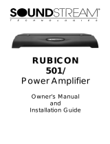
SAAii?P&~
SysTE/u
,#5,
(ME
ONfmY[l
4 channels
i3f
input,
3-way
mode
5
channel
operation with
s&Ilk
to
subwoofer
fading
2 channels high pass
(IweeterQ
2
channnels
midrange
subwoofer
channel
in low pass
CH162
r
--------
CH364
1
SOUND
Z-L’
I
!_
i_+
___J
./
\
\
Your
RUBICON
&
805 amplifiers are protected against both overheating and
short circuits by means of main power fuses and the following circuits:
+
Speaker Protection
+
Smart Power Supply Thermal Rollback
+
A fail-safe thermal protection circuit
AIOTE:
If
you
experience
bluwn
main power supply
fuses*
it is
like/j?
that the amplifier is seeing a
dsad
shorf,
either in the speaker
wire
or
in
the speaker
its&
Rectij/
fhe
problem
before
blowing multiple
fuses! DO NOT increase
values
beyond
the
original fuse value!
Doing
so
will
void your
warranfy
and may damage your
amplifer,
PROBLEM
No
Soti
and
povux
LED is not
.
Ilt
No somd, power LED is lit.
Amplifier
0lltpLlt
cUs off and on
repeatedly
Repeatedly blow amp fuse;
kequeti
activation of Smart
POVW
Swpiy
Circuit
Fuse LED is lit
CAUSE
1.
NopovuxorgrOudatthea~
2. No
renrlfe
tun0l-r
signal
3.
BIOVW
f&e
near the battery
1. No signal
inplrt
2.
The
AIRBASS/Accessory
switch
is in the
“IN
position
IMoW
it to the “OUT’ position
1. Speaker
o&p&
may be shorted
to ground. Check for resistivity
with
an
m
meter.
2. Speaker leads-may be shorted
to each other. Check for continuity
with
an
O~TYI
meter
1. Speaker or leads may be
Shorted
2.
Veriv
adequate
anp
Wtilation
The
powr
slrpplyhses
on the
bottom of the amplifier are
blown.
Your
Sound&-earn
RUBICON
amplifier is protected by a limited warranty.
Please read the enclosed warranty card for details.
20

SPECIFICATIONS
INSTALLATION NOTES AND DIAGRAMS
Channels
1
&
2; 3 & 4
I
I
MODEL
4
Q
Stereo
(8
a
Bridged)
(12.5 Vdc)
2
St
stereo
(4
Sz
Bridged)
(14.4 Vdc)
Subwoofer Channel
I I
MODEL
4n
(12.5 Vdc)
2n
(14.4 Vdc)
152
(14.4 Vdc)
I
THD
Signal to Noise
Frequency Response
Stereo Separation
Damping
Input Sensitivity
Input Impedance
<O.l%
>lOO
dB
20 Hz to 20
kHz
*
0.5
dB
>90
dB
>200
300
mV
to 5.0 Volts
10k
Ohms
Crossover Specifications
Low Pass: 30 Hz
-
120 Hz at 24 dB/Octave
High Pass: 65 Hz
-
220 Hz at 12 dB/Octave
Band Pass (805): 65
Hz
-
500
Hz at 12
dB/Octave
(Mid-Bass)
65 Hz
-
4
kHz
at 12 dB/Octave (Mid)
Hawkins Bass Control
0 to
+9
dB
Boost; Boost Frequency
= 45 Hz (Hawkins Bass Control “IN”)
Sub Sonic filter frequency = 13 Hz
Dimensions
(VI/x
D x H)
RUBICON405: 15.0” X 9.8” X 2.25”
(381 mm X 288mm X 57mm)
RUBICON805: 19.0” X 9.8” X 2.25” (483mm X 288mm X 57mm)
22
/