Page is loading ...

ASSEMBLY & INSTALLATION INSTRUCTIONS
All instructions must be handed to the user for
safekeeping.
Please note : Except where otherwise stated, all rights, including copy-
right in the text, images and layout of this booklet is owned by Focal
Point Fires plc. You are not permitted to copy or adapt any of the con-
tent without the prior written permission of Focal Point Fires plc.
1
Revision B - 10/13
© 2013 Focal Point Fires plc.
Focal Point Fires plc.
Christchurch, Dorset BH23 2BT
Tel: 01202 499330
Fax: 01202 499326
www.focalpointfires.co.uk
e : [email protected].uk
Questions or problems with your appliance?
Don’t take it back to the store
just give us a call on 01202 588601 we’re here to help
lines open between 9am and 5pm, Monday to Friday
MODELS COVERED BY THESE INSTRUCTIONS
KINGSWOOD

A S S E M B L Y I N S T R U C T I O N S
2
GB IE
1.0 IMPORTANT NOTES
© 2013 Focal Point Fires plc.
Section
1.0
2.0
3.0
4.0
5.0
6.0
7.0
Contents
Important notes
Tools required
Hardware & parts list
Assembly
Installation
Cleaning/finishing
Guarantee - terms and conditions
Page No.
2
2
2
3
8
9
9
2.0 TOOLS REQUIRED
CODE NAME ITEM QUANTITY
A
WOOD
DOWELS
(8X20mm)
16PCS
B CAM BOLTS
(6X30mm)
10PCS
C CAM LOCKS
(15X12mm)
10PCS
D SCREWS
(8X25mm)
4PCS
E SCREWS
(8X38mm)
2PCS
F SCREWS
(3X20mm)
4PCS
G WALL PLUGS
(6X25mm)
2PCS
3.0 HARDWARE & PARTS LIST
CODE NAME ITEM QUANTITY
①
MANTLE TOP 1PC
②
LEFT LEG 1PC
③
RIGHT LEG 1PC
④
FRONT PANEL 1PC
⑤
LEFT SIDE
PANEL
1PC
⑥
RIGHT SIDE
PANEL
1PC
⑦
INSIDE
PANELS
3PC
To ensure safe and stable installation:
1. The assembled Fire Surround can be fixed / secured to wall.
2. The wall must be sturdy and in good repair.
3. Some walls require alternative fixings (not included).
4. When drilling into the wall, check for hidden pipes and cables.
5.There are two options for construction of this surround:
A - with rebates - If you are installing this surround with a gas fire, or an electric fire where there is space in the wall to recess
the fire, use parts 7. This means the laminate is up against the wall.
B - without rebates - If using this surround with an electric fire and a flat wall, do not use with rebates, instead use the spacer
frame from the fire.
Cross head screwdriver PZ2 (3 inches in length or greater)
Drill, 6mm and a 2mm suitable drill bit
Pencil
Tape measure
Jigsaw or fine tooth saw

3.0 HARDWARE & PARTS LIST - CONTINUED
3
GB IE
© 2013 Focal Point Fires plc.
STEP 1
Insert 3x cam locks (C) into the right hand side panel (6), ensuring that the cross heads are facing outwards so it can be tight-
ened later on. Using a cross head screwdriver, screw the 3x cam bolts (B) into the right leg. Offer the side panel up to the leg
to make sure the inserts are in the correct orientation making sure that the cam locks are facing into the right leg and the leg
is not upside down. Next insert the wooden 20mm dowels (A) into the right leg, using a small amount of glue (C). With the
glue on both ends of the dowel joints, insert the right panel onto the right leg. When in the correct position, you are able to
tighten the cam locks with a PZ2 screw driver or the allen key supplied (K).
CODE NAME ITEM QUANTITY
H
MIRROR
PLATES
(45X43mm)
2PCS
I
SCREWS
(8X44mm)
9PCS
J GLUE
(10g)
1PCS
K ALLEN KEY
(4X57mm)
1PCS
L
WOOD
DOWELS
(8X30mm)
20PCS
M SCREWS
(3X32mm)
15PCS
N
ROUND
HEAD
SCREWS15mm
9PCS
CODE NAME ITEM QUANTITY
⑧
TOP PANEL 1PC
⑨
FRONT FACE
PANEL
1PC
⑩
LEFT FACE
PANEL
1PC
⑪
RIGHT FACE
PANEL
1PC
⑫
FRONT
BOTTOM
PANEL
1PC
⑬
LEFT
BOTTOM
PANEL
1PC
⑭
RIGHT
BOTTOM
PANEL
1PC
⑮
BACK PANEL 1PC
⑯
TRIANGLE
PANELS
4PCS
⑰
LAMINATE
BACK PANEL
1PC
⑱
LAMINATE
HEARTH
PANEL
1PC
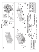
4.0 ASSEMBLY
B
B
B
A
A
C
C
C
⑥
③
Fixings Parts
A x 2 PCS 3
B x 3 PCS 6
C x 3 PCS

4.0 ASSEMBLY - CONTINUED
GB IE
4
© 2013 Focal Point Fires plc.
To assemble the left side please follow the same method used to complete the right hand side in the previous section.
STEP 2
STEP 3
Gently lay both legs you have prepared onto a suitable protected surface. Be extremely careful not to scratch the front edges
of the legs. DO NOT DRAG THE LEGS! Make sure that the legs are lifted everytime they are moved to avoid them from being
damaged.
Now lay the left hand leg on your right and the right hand leg on your left, both facing downwards. Insert 2x 20mm dowels
with glue (A) into the left and right hand legs. Now position the front panel onto the dowel joints in the legs to ensure the legs
are at the correct distance apart also checking that the front panel is the correct way around with the 4 holes positioned on
the bottom edge. Next glue the dowels into position. Once in you are then able to screw the 4 x25mm screws (D) into posi-
tion.
A
A
B
B
B
C
C
C
A
D
D
D
D
⑤
②
④
Fixings Parts
A x 2 PCS 2
B x 3 PCS 5
C x 3 PCS
Fixings Parts
A x 4 PCS 4
D x 4 PCS
If fitting with a rebate. If rebates are not being used go to step 5
Now join all 3 inside panels (7) to the rear of the surround via 6 dowels. Once glued into position screw 9x 44mm screws (I)
to secure the surround together. Ensure the labels on the rebates are facing outwards.
Fixings Parts
A x 6 PCS 7
I x 9 PCS
STEP 4
A
A
A
A
A
A
A
A
A
I
I
I
I
I
I
I
I
I
⑦
⑦
⑦

4.0 ASSEMBLY - CONTINUED
GB IE
5
© 2013 Focal Point Fires plc.
Insert 2 cam locks (C) into each leg. Next prepare the mantle top (1) by screwing all 4 cam bolts (B) into position. The dowel
joints (A) need to be glued in at both ends of the top mantle. Connect the top mantle to the surround, making sure all 6
inserts are in their correct position. Once home, all 4 cam locks (C) can be tightened into position.
A
A
B
B
B
C
C
①
A
B
B
C
C
Fixings Parts
A x 2 PCS 1
B x 4 PCS
C x 4 PCS
STEP 6
17
H
W
Cutting & Fitting the Laminate Backpanel
Using a pencil, mark out a rectangular shape on the Backpanel (17) to 570mm H x419mm W (sizes indicated may vary depend-
ing on the fire being used - please check) and then cut out the aperture with a fine toothed saw or jigsaw. Drill the laminate
panel at the edges to enable to attach to the back of the cleats/surround. The holes should be 1-2mm oversized, (larger than
the screws to be used) to allow for expansion. Gently, screw the panel into position with the 9x15mm Round Headed Screws
(N) DO NOT OVERTIGHTEN!
STEP 7
L
M
⑯
⑭
Fixings Parts
L x 1 PC 16
M x 1 PC 14
Connect a triangular panel (16) to the right bottom panel (14) with a dowel joint (L) and glue (J). Next screw the two pieces
together with a 32mm screw (M).
STEP 5
C
C
B
Fixings Parts
N x 9 PCS 17
N
N
N
N
N
N
N
N
N

4.0 ASSEMBLY - CONTINUED
GB IE
6
© 2013 Focal Point Fires plc.
Join 2 triangle panels (16) to both ends of the back panel (15). Again glue the dowels (L) into position and then screw the two
components together with 2x 32mm screws (M).
L
M
L
M
⑯
⑮
⑯
Fixings Parts
L x 2 PCS 15
M x 2 PCS 16
Prepare the left bottom in the same way.
L
M
⑯
⑬
Fixings Parts
L x 1 PC 13
M x 1 PC 16
L
M
⑮
⑭
⑬
Fixings Parts
L x 4 PCS 13
M x 2 PCS 14
15
Connect both ends of the hearth to the back panel with 2 dowel joints (L) in each end and 1x 32mm screw (M).
STEP 8
STEP 9
STEP 10
M
L
L
L

4.0 ASSEMBLY - CONTINUED
GB IE
7
© 2013 Focal Point Fires plc.
L
L
M
M
L
L
⑮
⑫
⑩
⑨
⑪
Fixings Parts
L x 2 PCS 12
M x 2 PCS 15
Fixings Parts
L x 4 PCS 9
10
11
Next join the front bottom panel (12) to the rest of the hearth using the same method as previously. Ensure that the front bot-
tom panel is connected the correct way up with all the screw holes facing upwards.
Connect both left (10) and right hand face panels (11) to the front face panel (9) via 2x dowel joints (L) with glue at both ends.
STEP 13
L
L
L
L
L
M
M
M
M
M
M
L
Fixings Parts
L x 6 PCS 9
M x 7 PCS 10
11
12
13
14
15
M
With the face panels upside down insert 6x dowel pins (L) with glue (J). Next install the hearth on top, so you are able to
screw through the hearth and into the face panel with 7x 32mm screws (M).
STEP 11
STEP 12
L
L
⑫
⑨
⑩
⑪
⑮
⑬
⑭

8
© 2013 Focal Point Fires plc.
4.0 ASSEMBLY - CONTINUED
GB IE
Slide the hearth laminate (18) in to sit on top of the top panel.
STEP 14
Lay the hearth tray on the floor and slide the top panel (8) into position.
⑧
18
5.0 INSTALLATION
G
H
F
E
G
F
E
Fixings
E x 2 PCS
F x 4 PCS
G x 2 PCS
H x 2 PCS
H
With a pencil mark out the desired height in which you would like the mirror brackets (H) to be situated on the rear of the legs. To
avoid splitting the leg, pre drill the bracket holes with a 2mm drill bit. Now attach the brackets to the legs using the 3x20mm screws (F).
Once the brackets are in position, centre and level the hearth into its final fitting position. Position the surround on the hearth to cor-
respond with the header/fireplace lintel, mark with a pencil on the wall where you wish to drill. Remove the surround from the position
and prepare the wall from the marked positions. If using the fixings supplied, drill a pilot hole in the wall using a 6mm drill bit. If not, use
a suitable drill bit for the wall plugs you are using. Insert the wall plugs into position offering the surround back up into position against
the wall. You are now able to secure the surround to the wall using the 8x38mm screws (E).
STEP 15
F
F
Parts
8
Parts
18

9
© 2013 Focal Point Fires plc.
6.0 CLEANING/ FINISHING
GB IE
F861226
7.0 GUARANTEE - TERMS AND CONDITIONS
The 3 year guarantee commences from the date of purchase, provided that the following 3 terms and conditions are adhered
to:
Registration is not required.
1. For any claim to be made within the 3 years from date of purchase you will be required to provide and supply us with your
proof of purchase.
2. Your gas fire must have been commissioned by a CORGI/Gas Safe* registered installer, evidence of which you must provide
together with the CORGI/Gas Safe* registration number.
3. Your appliance must have been serviced annually, irrespective of use, by a CORGI/Gas Safe* registered installer, evidence of
which must be provided, such as the receipt.
Please note all consumable items such as any ceramics including; coals, pebbles, the matrix, front strips, side cheeks, rear panels
and tapered rear panels are not covered by the 3 year guarantee.For all Electric fires purchased the 3 year guarantee com-
mences from the date of purchase, providing that you can supply the proof of purchase. This does not cover consumable items
such as pebbles, coals or light bulbs.
Making a claim is easy.
If you wish to make a claim under our 3 year guarantee and all the terms and conditions for your product have been met then
please submit the following information for the attention of the 3G Service Department to the address below. Alternatively, you
can email or fax.Please note that this does not affect your statutory rights.
Focal Point Fires plc, 3G Service Department, Reid Street, Christchurch, Dorset, BH23 2BT.
Alternatively email: 3g@focalpointfires.co.uk or fax. 01202 499326.
Details required:
1. Name, full address including post code and contact telephone number.
2. Receipt of purchase or credit card statement.
3. Original installers CORGI/Gas Safe* registration number (gas fires only).
4. Annual service receipt for every 12 months (gas fires only).
*Gas Safe Register replaced CORGI as the gas registration body in Great Britain and the Isle of Man on 1st April 2009.
Disclaimer:
The components of this mantle are ash veneered MDF. As such, it is likely that there will be variations in the appearance, tex-
ture, grain structure and colour etc., of the individual components.
Caution: Wood products may produce splinters, so care should be taken during assembly.
Warning: This mantle is not designed for heavy use. Care should be taken to distribute weight evenly.
Note: Wall plugs supplied are for masonry or solid wall fixing only. For any other type of wall seek professional advice.
As our policy is one of continuous improvement and development, we hope therefore you understand we must retain the right to amend details and/or specifications without prior notice.
Before carrying out any of the following operations, ensure that the applaince is OFF and completely cold. Regularly clean
around the appliance to ensure that dust, fluff, pet hair etc, are kept to a minimum. There are no other specific requirements for
care, other than regular cleaning of the general appliance.
A wipe with a dry cloth is normally sufficient. DO NOT use abrasuve cleaners as they can damage the finish. Test in a hidden
part before cleaning. Clean only in the direction of the grain. Regularly check the surround is securely fixed in position.
/