Shinko JIR-301-M User manual

Type
User manual

Shinko JIR-301-M is a versatile digital indicator designed for precise measurement and display of various process variables. With its advanced features, it offers reliable monitoring and control solutions for a wide range of industrial applications.

Shinko JIR-301-M is a versatile digital indicator designed for precise measurement and display of various process variables. With its advanced features, it offers reliable monitoring and control solutions for a wide range of industrial applications.

INSTRUCTION MANUAL DIGITAL INDICATOR JIR-301-M
No. JIR31JE3 2019.03
SHINKO TECHNOS CO., LTD. Head office: 2-5-1, Senbahigashi, Minoo, Osaka, 562-0035, Japan
TEL: +81-72-727-6100 FAX: +81-72-727-7006 URL: http://www.shinko-technos.co.jp/e/ E-mail: [email protected]
Thank you for purchasing our JIR-301-M, Digital Indicator. This manual contains instructions for the mounting, functions, operations and notes when operating the
JIR-301-M. To ensure safe and correct use, thoroughly read and understand this manual before using this instrument. To prevent accidents arising from the misuse
of this instrument, please ensure the operator receives this manual.
Safety Precautions
(Be sure to read these precautions before using
our products.)
The safety precautions are classified into 2 categories: “Warning” and “Caution”.
Warning: Procedures which may lead to dangerous conditions and cause death or
serious injury, if not carried out properly.
Caution: Procedures which may lead to dangerous conditions and cause superficial
to medium injury or physical damage or may degrade or damage the product,
if not carried out properly.
• No large capacity electromagnetic switches or cables through which large current is flowing
• No water, oil or chemicals or where the vapors of these substances can come into direct
contact with the unit
• Please note that the ambient temperature of this unit – not the ambient temperature of the
control panel – must not exceed 50 (122 ) if mounted through the face of a control panel,
otherwise the life of electronic components (especially electrolytic capacitors) may be
shortened.
Wiring Precautions
• Do not leave wire remnants in the instrument, as they could cause a fire or malfunction.
Use the solderless terminal with an insulation sleeve in which the M3 screw fits when wiring
the instrument.
The terminal block of the JIR-301-M is designed to be wired from the upper side. The
lead wire must be inserted from the upper side of the terminal, and fastened by the
terminal screw.
• Tighten the terminal screw using the specified torque. If excessive force is applied to the
screw when tightening, the terminal screw or case may be damaged.
(0.63 N•m of torque is recommended.)
• Do not pull or bend the lead wire on the terminal side when wiring or after wiring, as it could
cause malfunction.
This instrument does not have a built-in power switch, circuit breaker and fuse. It is
necessary to install a power switch, circuit breaker and fuse near the instrument.
(Recommended fuse: Time-lag fuse, rated voltage 250 V AC, rated current 2 A)
• For the grounding wire, use a thick wire (1.25 - 2.0 mm
2
).
• For a 24 V AC/DC power source, ensure polarity is correct
when using direct current (DC).
Do not apply a commercial power source to the sensor which is connected to the input
terminal nor allow the power source to come into contact with the sensor.
Use a thermocouple and compensating lead wire according to the sensor
input
specifications of this instrument.
• Use the 3-wire RTD according to the sensor input specifications of this instrument.
• When using a relay contact output type, externally use a relay according to the capacity of
the load to protect the built-in relay contact.
• When wiring, keep input wires (thermocouple, RTD, etc.) away from AC power sources or
load wires.
Warning
• To prevent an electric shock or fire, only Shinko or other qualified service personnel may
handle the inner assembly.
To prevent an electric shock, fire or damage to the instrument, parts replacement may
only be undertaken by Shinko or other qualified service personnel.
SAFETY PRECAUTIONS
To ensure safe and correct use, thoroughly read and understand this manual before
using this instrument.
This instrument is intended to be used for industrial machinery, machine tools and
measuring equipment. Verify correct usage after purpose-of-use consultation with our
agency or main office. (Never use this instrument for medical purposes with which
human lives are involved.)
External protection devices such as protective equipment against excessive temperature
rise, etc. must be installed, as malfunction of this product could result in serious damage
to the system or injury to personnel. Proper periodic maintenance is also required.
This instrument must be used under the conditions and environment described in this
manual. Shinko Technos Co., Ltd. does not accept liability for any injury, loss of life or
damage occurring due to the instrument being used under conditions not otherwise
stated in this manual.
Mounting Precautions
This instrument is intended to be used under the following environmental conditions
(IEC61010-1)]: Overvoltage category , Pollution degree 2
Ensure the mounting location corresponds to the following conditions:
A minimum of dust, and an absence of corrosive gases
• No flammable, explosive gases
• No mechanical vibrations or shocks
• No exposure to direct sunlight, an ambient temperature of 0 to 50 (32 to 122 )
(No icing)
An ambient non-condensing humidity of 35 to 85 %RH
Caution with Respect to Export Trade Control Ordinance
To avoid this instrument from being used as a component in, or as being utilized in the
manufacture of weapons of mass destruction (i.e. military applications, military equipment,
etc.), please investigate the end users and the final use of this instrument. In the case of
resale, ensure that this instrument is not illegally exported.
Specifications
Power
supply
100-240 V AC 50/60 Hz
Allowable fluctuation range:
85 to 264 V AC Transmission Resolution: 12000
24 V AC/DC 50/60 Hz
Allowable fluctuation range:
20 to 28 V AC/DC output 1
Direct current: 4 to 20 mA DC (Load resistance: Max. 550 )
Power
consumption
100-240 V AC:Approx.8 VA (When max. options ordered: Approx.10 VA) Response time: 400 ms+ Input sampling period (0%90%)
24 V AC: Approx.6 VA (When maximum options ordered: Approx. 9 VA) Alarm output 4 Relay contact 1a: Control capacity:3 A 250 V AC(resistive load)
24 V DC: Approx.4 W (When maximum options ordered: Approx. 7 W) (A4 option) Electrical life: 100,000 cycles
Ambient temperature 0 to 50 (32 to 122 ) Insulated power Output voltage: 24 3 V DC (when load current is 30 mA)
Ambient humidity 35 to 85 %RH (Non-condensing) output Ripple voltage: Within 200 mV DC (when load current is 30 mA)
Indication
accuracy
Thermocouple: Within 0.2% of each input span 1 digit, However, (P24 option) Max load current: 30 mA DC
R, S input, 0 to 200 (32 to 392 ): Within 6 (12 ) Insulated power Output voltage: 5 0.5 V DC (when load current is 30 mA)
B input, 0 to 300 (32 to 572 ): Accuracy is not guaranteed. output Ripple voltage: Within 200 mV DC (when load current is 30 mA)
K, J, E, T, N input, Less than 0 (32 ): Within 0.4% of input span (P5 option) Max load current: 30 mA DC
1 digit Power for 2-wire Output voltage: 24 3 V DC (when load current is 30 mA)
RTD: Within 0.1% of each input span 1 digit, or within 1 (2 ) transmitter Ripple voltage: Within 200 mV DC (when load current is 30 mA)
whichever is greater (DSB option) Max load current: 30 mA DC
Direct current, DC voltage input: Within 0.2% of input span 1 digit Transmission Resolution: 12000
Input sampling period 125 ms output 2 Output accuracy: Within 0.3% of transmission output span
Weight Approx. 300 g (T2 option) Response time: 400 ms + Input sampling period (0%90%)
Accessories Screw type mounting brackets: 1 set
Direct current: 4 to 20 mA DC (Load resistance: Max. 550 )
Instruction manual excerpt: 1 copy
0 to 20 mA DC (Load resistance: Max. 550 )
Unit label: 1 label
DC voltage: 0 to 1 V DC (Load resistance: Minimum 100 k )
Terminal cover: 1 piece (when the TC option is ordered)
0 to 5 V DC (Load resistance: Minimum 500 k )
A1 output Relay contact 1a: Control capacity: 3 A 250 V AC (resistive load)
1 to 5 V DC (Load resistance: Minimum 500 k )
A2 output Electrical life: 100,000 cycles
0 to 10 V DC (Load resistance: Minimum 1 M )
A3 output
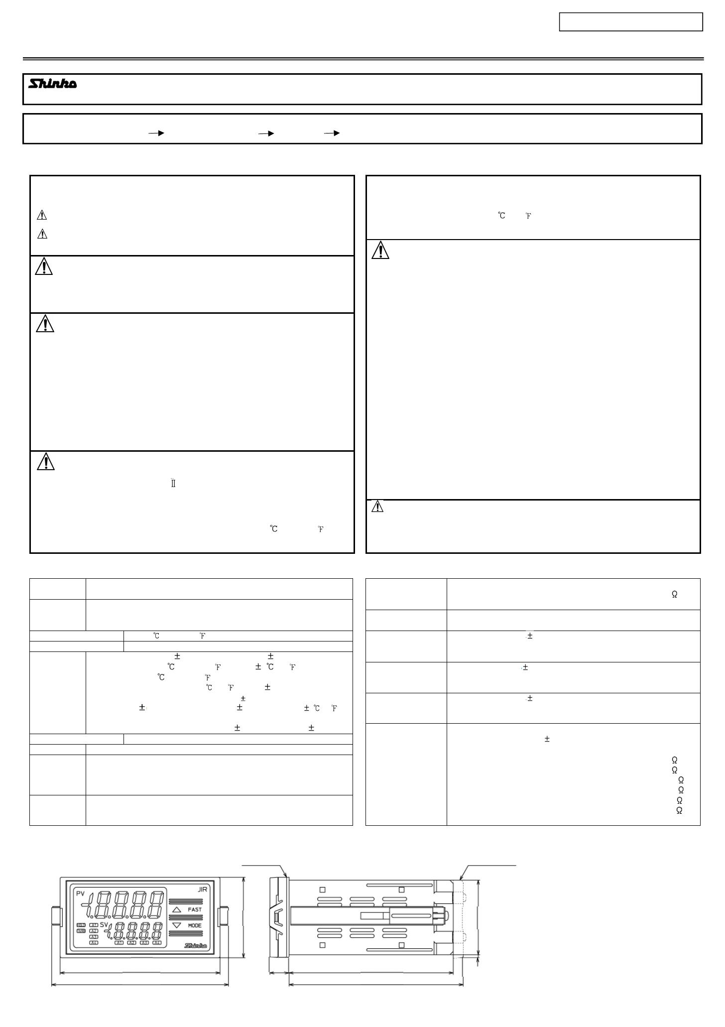
External dimensions (Scale: mm)
For detailed usage, refer to the Instruction Manual for the JIR-301-M. Please download the full Instruction Manual from the Shinko Technos website.
http://shinko-technos.co.jp/e/ Support & Downloads Downloads Manuals
和文は裏面をご覧下さい。
Gasket Terminal cover
48
44.5
2(*)
11.5
98.5
104.5(*)
96
106.2
(*) When terminal cover is used
Panel Cutout (Scale: mm)
Mounting of the Unit
Caution
As the case of the JIR-301-M is made of resin, do not use excessive force while tightening screws, or the mounting brackets
or case could be damaged. 0.12 Nm of torque is recommended.
Mounting of the Unit
Mount the instrument vertically to the flat, rigid panel
to ensure it adheres to the Drip-proof/Dust-proof
specification (IP66).
If vertical close mounting is used for the instrument,
IP66 specification (Drip-proof/Dust-proof) may be
compromised, and all warranties will be invalidated.
Mountable panel thickness: 1 to 8 mm
(1) Insert the instrument from the front side of the
control panel.
(2) Attach the mounting brackets by the slots on the
right and left sides of the case, and secure the
instrument in place with the screws.
0.12 N•m of torque is recommended.
Name and Functions
Display, Indicator
Name Description
PV Display Indicates PV (process variable) or characters in the setting mode with the red LED.
SV Display Indicates A1/A2/A3/A4 value or the set value in the setting mode with the green LED.
HOLD indicator When PV is held (HOLD, Peak HOLD, Bottom HOLD), the yellow LED lights.
TX/RX indicator The yellow LED lights during Serial communication (C5 option) TX (transmitting) output.
A1 value indicator When A1 value is indicated on the SV Display, the green LED lights.
A2 value indicator When A2 value is indicated on the SV Display, the green LED lights.
A3 value indicator When A3 value is indicated on the SV Display, the green LED lights.
A4 value indicator When A4 value is indicated on the SV Display, the green LED lights. (A4 option)
A1 action indicator When A1 output is ON, the red LED lights. Flashes during A1 output HOLD.
A2 action indicator When A2 output is ON, the red LED lights. Flashes during A2 output HOLD.
A3 action indicator When A3 output is ON, the red LED lights. Flashes during A3 output HOLD.
A4 action indicator When A4 output is ON, the red LED lights. Flashes during A4 output HOLD. (A4 option)
Key
Name Description
UP key Increases the numeric value.
If High/Low limit range alarm is selected in [A4 type], and if the SV Display indicates A4 value, the SV
Display indicates A4 high limit value while the UP key is pressed.
FAST key
Makes the set value change faster while holding down the UP/DOWN key and FAST key together.
DOWN key Decreases the numeric value.
MODE key Selects the setting mode, and registers the set value.
Caution
If vertical close mounting is used for the instrument, IP66 specification (Drip-
proof/Dust-proof) may be compromised, and all warranties will be invalidated.
Vertical close mounting
n: Number of mounted units
130
92
+0.8
0
n×48-3
+0.5
0
92
+0.8
0
45
+0.5
0
FAST key
UP key
PV Display
SV Display
HOLD indicator
TX/RX indicator
A1-A4 value indicators
A1-A4 action indicators
DOWN key MODE key
Set value lock
Unlock
Lock 1
Lock 2
Lock 3
Communication protocol
Shinko protocol
MODBUS ASCII mode
MODBUS RTU mode
Shinko protocol
(Block read available)
MODBUS ASCII mode
(Block read available)
MODBUS RTU mode
(Block read available)
Communication speed
2400 bps
4800 bps
9600 bps
19200 bps
38400 bps
Parity
No parity
Even
Odd
Stop bit
1 bit
2 bits
Input type
K -200 to 1370
K -200.0 to 400.0
J -200 to 1000
R 0 to 1760
S 0 to 1760
B 0 to 1820
E -200 to 800
T -200.0 to 400.0
N -200 to 1300
PL- 0 to 1390
C(W/Re5-26) 0 to 2315
Pt100 -200.0 to 850.0
JPt100 -200.0 to 500.0
Pt100 -200 to 850
JPt100 -200 to 500
K -320 to 2500
K -200.0 to 750.0
J -320 to 1800
R 0 to 3200
S 0 to 3200
B 0 to 3300
E -320 to 1500
T -200.0 to 750.0
N -320 to 2300
PL- 0 to 2500
C(W/Re5-26) 0 to 4200
Pt100 -200.0 to 1000.0
JPt100 -200.0 to 900.0
Pt100 -300 to 1500
JPt100 -300 to 900
4 to 20 mA DC -2000 to 10000
(
Externally mounted 50 shunt resistor)
0 to 20 mA DC -2000 to 10000
(
Externally mounted 50 shunt resistor)
0 to 1 V DC -2000 to 10000
0 to 5 V DC -2000 to 10000
1 to 5 V DC -2000 to 10000
0 to 10 V DC -2000 to 10000
4 to 20 mA DC -2000 to 10000
(Built-in 50 shunt resistor)
0 to 20 mA DC -2000 to 10000
(Built-in 50 shunt resistor)
Decimal point place
No decimal point
1 digit after decimal point
2 digits after decimal point
3 digits after decimal point
A1/A2/A3/A4 type
No alarm action
High limit alarm
Low limit alarm
High limit with standby alarm
Low limit with standby alarm
H/L limit range alarm(A3, A4 only)
A1/A2/A3/A4 Energized/De-energized
Energized
De-energized
Event input function
HOLD
Peak HOLD
Bottom HOLD
Alarm HOLD 1
Alarm HOLD 2
A1/A2/A3/A4 HOLD function
Disabled
Enabled
Square root function
Disabled
Enabled
A1/A2/A3/A4 output ON/OFF
Output OFF
Output ON
Terminal Arrangement
Warning
• Turn the power supply to the instrument off before wiring or checking. Working on or touching the terminal with the power switched on may
result in severe injury or death due to electrical shock.
Tighten the terminal screw using the specified torque. 0.63 N•m of torque is recommended.
Selection Item
Terminal Code Description
GND Ground
PWR Power supply voltage 100 to 240 V AC or 24 V AC/DC
For a 24 V AC/DC power source, ensure polarity is correct
when using direct current (DC).
TRANSMIT OUTPUT1 Transmission output 1
A1 A1 output
A2 A2 output
A3 A3 output
EVENT INPUT Event input
TC Thermocouple input
RTD RTD input
DC
Direct current input, DC voltage input
F
connect a 50 shunt resistor between input terminals.
P24
Insulated power output 24 V (P24 option)
P5
Insulated power output 5 V (P5 option)
RS-485
Serial communication (RS-485)(C5 option)
TRANSMIT OUTPUT2 Transmission output 2 (T2 option)
A4 A4 output (A4 option)
A Direct current input (DSB option)
24V Power for 2-wire transmitter (DSB option)
Key Operation Flowchart
[About setting item]
Upper left: PV Display: Indicates the setting item characters.
Lower left: SV Display: Indicates the factory default. Right side: Setting item
: Available only when option is ordered.
If Serial communication (RS-485)[C5 option] is ordered, [Event input function] will not be available.
[About key operation]
+ : Press the and key (in that order) together. The unit will move to the next setting
item, illustrated by an arrow.
: Press the key. The unit will move to Alarm setting mode.
+ (3 sec): Press the and key (in that order) together for approx. 3 seconds. The unit will
move to Auxilary function setting mode 1.
+ + (3 sec): Press the , and keys (in that order) together for approx. 3 seconds.
The unit will move to Auxiliary function setting mode 2.
+ (5 sec): Press the and keys (in that order) together for approx. 5 seconds. The unit will
move to
Maintenance mode.
A1 value Input type A1 output
ON/OFF
Power ON
PV
A1 value
A1 value is
displayed.
A2 value
A3 value
A4 value
PV
A2 value
A2 value is
displayed.
PV
A3 value
A3 value is
displayed.
PV
A4 value
A4 value is
displayed.
PV/SV Display Mode
Alarm setting mode
A4 high limit
value
Set value lock
Sensor correc-
tion coefficient
Sensor
correction
Communication
protocol
Auxiliary function setting mode 1
Instrument
number
Communication
speed
Parity
Stop bit
+
+
+
+
Auxiliary function setting mode 2
Scaling high limit
Scaling low limit
Decimal point
place
PV filter time
constant
A1 type
A2 type
A3 type
A4 type
A1 Energized/
De-energized
A2 Energized/
De-energized
A3 Energized/
De-energized
A4 Energized/
De-energized
A1 hysteresis
A3 hysteresis
A4 hysteresis
A1 delay time
A2 delay time
A3 delay time
A4 delay time
Transmission
output 1 high limit
Transmission
output 1 low limit
Transmission
output 2 high limit
Transmission
output 2 low limit
Event input
function
A1 HOLD
function
A2 HOLD
function
A3 HOLD
function
A4 HOLD
function
Square root
function
Low level cutoff
A2 output
ON/OFF
A3 output
ON/OFF
A4 output
ON/OFF
Trans. output 1
manual output
Trans. output 2
manual output
Maintenance mode
+ + (3 sec) + (5 sec)
A1 value
+
(3 sec)
Abbreviations:
Trans.: Transmission
A2 hysteresis
  • Page 1 1
  • Page 2 2
  • Page 3 3
  • Page 4 4

Shinko JIR-301-M User manual

Type
User manual

Shinko JIR-301-M is a versatile digital indicator designed for precise measurement and display of various process variables. With its advanced features, it offers reliable monitoring and control solutions for a wide range of industrial applications.

Ask a question and I''ll find the answer in the document

Finding information in a document is now easier with AI