Page is loading ...

Conguration via DIP switch
Select the operating mode using the two DIP switches SW1 and SW2:
SW1 SW2 Communication mode
OFF OFF RS422 mode, RS485 4-wire mode
OFF ON
ON OFF RS485 2-wire mode (non-echo)
ON ON RS485 2-wire mode (echo)
If the RS422 or RS485 4-wire mode is selected, the DIP switches SW3 and SW4 are used
to activate/deactivate the terminating resistor (activate at the beginning and at the end of the
wiring):
SW3 Activate/deactivate the terminating resistor for 4-wire mode at the
receiver side
OFF Terminating resistor deactivated
ON Terminating resistor activated
SW4 Activate/deactivate the terminating resistor for 4-wire mode at the
transmitter side
OFF Terminating resistor deactivated
ON Terminating resistor activated
If the RS485 2-wire mode is selected, the DIP switch SW4 is used to activate/deactivate the
terminating resistor:
SW4 Activate/deactivate the terminating resistor for 2-wire mode at the
receiver and the transmitter side
OFF Terminating resistor deactivated
ON Terminating resistor activated
Transmission speed/cable length
The achievable baud rate may differ from the following tables depending on the
cable, ambient conditions, etc. The use of shielded cables is recommended for EIA-
422 and EIA-485 (CAT5, EIA/TIA/ANSI-568).
The tables were created using a CAT5e UTP cable at room temperature.
a) RS422 mode, RS485 4-wire mode
Baud rate Cable length
300 m 600 m 900 m 1200 m
9600 x x x x
19200 x x x x
38400 x x x x
57600 x x x x
115200 x x x x
230400 x x x -
460800 x x - -
921600 x x - -
b) RS485 2-wire mode (non-echo/echo)
Baud rate Cable length
300 m 600 m 900 m 1200 m
9600 x x x x
19200 x x x x
38400 x x x x
57600 x x - -
115200 x x - -
230400 x x - -
460800 x - - -
921600 x - - -
Using the terminals
The wire of the connection cable is pushed straight into a connection terminal (stripping the
cable about 6 - 7 mm).
In order to remove the wire from the terminal, press the corresponding white release button by
using for example a at screwdriver while pulling the wire out of the terminal simultaneously. Do
not use force when pulling out the wire or pressing the release button.
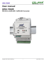
Operating instructions
RS232 to RS422/RS485 Converter
Item no. 1693714
Intended use
This product is used for the connection of a device with RS422/RS485 interface to a RS232
port.
The voltage/power is supplied either via RS232 or via the two “PWR” terminals.
For safety and compliance reasons, the product must not be converted or modied in any way.
If you use the product for other purposes than those described above, the product may be dam-
aged. Moreover, improper use involves risks such as short-circuits, re, electric shocks, etc.
Please read the operating instructions carefully and do not discard them. Please include these
operating instructions when you pass the product on to a third party.
This product complies with the applicable national and European Regulations. All names of
companies and products are the trademarks of the respective owners. All rights reserved.
Package contents
• Converter
• Operating instructions
Up-to-date operating instructions
Download the latest operating instructions via the link www.conrad.com/downloads or scan the
QR code. Follow the instructions on the website.
Explanation of symbols
An exclamation mark in a triangle indicates important instructions in these operating
instructions which absolutely have to be observed.
The arrow symbol indicates specic tips and advice on operation.
Safety instructions
Please read the operating instructions carefully and pay particular attention
to the safety instructions. We do not assume liability for any injuries/mate-
rial damages resulting from failure to observe the safety instructions and the
information in these operating instructions regarding the proper use of the
product. Furthermore, in such cases, the warranty/guarantee will be null and
void.
• The product is not a toy. Keep out of the reach of children and pets.
• Do not carelessly leave the packaging material lying around. It may become a
dangerous plaything for children.
• Protect the product from extreme temperatures, direct sunlight, strong vibrations
and combustible gases, vapours and solvents.
• Never expose the product to mechanical stress. Please handle the product care-
fully. The product can be damaged if crushed, struck or dropped, even from a low
height.
• If safe operation is no longer possible, take the device out of service and secure
it against unintended use. Safe operation is no longer possible, if the product:
- shows visible damage,
- no longer functions properly,
- has been stored under adverse ambient conditions for an extended period of
time or
- has been exposed to considerable strain during transport.
• Also observe the safety and operating instructions of any other devices that are
connected to this product.
• If you have doubts about how the product should be operated or how to safely
connect it, consult a qualied technician.
• Maintenance, adjustment and repair work should only be carried out by an expert
or a specialised workshop.
• If you have any questions that are not answered in these operating instructions,
please contact our technical customer service or other professionals.

This is a publication by Conrad Electronic SE, Klaus-Conrad-Str. 1, D-92240 Hirschau (www.conrad.com).
All rights including translation reserved. Reproduction by any method, e.g. photocopy, microlming, or the capture in
electronic data processing systems require the prior written approval by the editor. Reprinting, also in part, is prohibited.
This publication represent the technical status at the time of printing.
© Copyright 2018 by Conrad Electronic SE. 1693714_V3_0818_02_m_VTP_en
Voltage/power supply
a) Via RS232
The converter can be powered via RS232 (TXD, RTS, DTR connection) (follow information
on the RS232 interface you are using). Power LED “ ” on the converter lights up, if voltage/
power properly supplied.
If a number of RS422 / RS485 devices are connected to the converter, voltage/
power should be supplied via the terminals, see b).
b) Via terminals
6 terminals are located on the back of the converter. An external voltage/power supply is con-
nected via the two “PWR” terminals (5 - 9 V/DC, polarity irrelevant). Power LED “
” on the
converter lights up, if voltage/power properly supplied.
Connection
• Congure the DIP switches rst.
• Next do the wiring.
• Connect the converter to your RS232 interface. If used, connect the extension cable 1: 1. The
knurled-head screws on the side of the converter are used to fasten the converter securely
to the RS232 port.
• LED “
” lights up when voltage/power supply is correct.
• LED “T” is lit or ashes during data transmission (T = “Transmitting”).
• LED “R” is lit or ashes when data is received (R = “Receiving”).
Care and cleaning
• Disconnect the product from the mains supply before each cleaning procedure.
• Use a dry, lint-free cloth to clean the product.
• Never use abrasive cleaning agents, rubbing alcohol or other chemical solutions, since these
could damage the casing or even impair operation.
Disposal
Electronic devices are recyclable materials and do not belong in the household
waste. Dispose of an unserviceable product in accordance with the relevant statu-
tory regulations. That way you full your statutory obligations and contribute to the
protection of the environment.
Technical data
Operating voltage ......................... 5 - 9 V/DC
Power consumption ...................... approx. 10 mA at 5 V/DC
RS232 side:
Connection DE9 Female
Signals TXD, RXD, RTS, DTR, GND
Max. speed 1Mbps
Protection IEC 61000-4-2 (ESD), IEC 61000-4-4 (EFT), IEC 61000-4-5
(Surge)
RS422 and RS485 side:
Connection 6pin terminal block
Signals
RS422 TXD+, TXD-, RXD+, RXD-, GND
RS485 4-wire TXD+, TXD-, RXD+, RXD-, GND
RS485 2-wire TRXD+, TRXD-, GND
Mode RS422 point-to-point/multi-drop, RS485 echo/non-echo
(selected via DIP switch)
Data control Automatic Direction control (auto-toggling)
Max. speed 1Mbps
Protection IEC 61000-4-2 (ESD), IEC 61000-4-4 (EFT), IEC 61000-4-5
(Surge)
Terminator Activate/deactivate via DIP switch
Ambient conditions ....................... temperature -40 °C to +85 °C,
relative humidity 5% to 95%, noncondensing
Dimensions (W x L x H) ................ 38.5 x 42.5 x 18 mm
Weight .......................................... 21 g
Additional information
a) Pin assignment RS232
b) Pin assignment RS422/RS485
c) Connection example 1
RS422/RS485 4-wire cabling (master/slave system):
Terminators must be activated at both ends of the cable (at the master and at the last slave).
d) Connection example 2
RS485 2-wire cabling (multi master system)
Terminators must be activated at both ends of the cable (at both ends at the master).
/